


SERVICE MANUAL
VACUUM CLEANER
© E.H.P. Floor Care |
Number of |
|
|
“Elara” electronic |
|||
|
publication |
vacuum cleaner
59971 19-22
EN
|
|
|
|
|
|
|
Factory: |
|
|
Edition: 2009-02 |
|
|
|
|
|
|
|
||
|
|
|
|
|
|
|
|
|
|
|
EN |
|
Publication number |
599 71 19-22 |
Rev. 01 |
02/2009 |
|
PR - 1/42 |
|
Downloaded from www.Manualslib.com manuals search engine
TABLE OF CONTENTS
1 |
General description .................................................................................................................................... |
3 |
||
|
1.1 |
Exploded view....................................................................................................................................... |
4 |
|
2 |
ACCESSIBILITY......................................................................................................................................... |
6 |
||
3 Levels of Electronic Control...................................................................................................................... |
28 |
|||
|
3.1 |
Display Layout for models without remote controlled HBTN:............................................................. |
28 |
|
|
3.1.1 |
Basic software functionality........................................................................................................ |
28 |
|
|
3.1.2 |
Motor power regulation and LED-functionality........................................................................... |
28 |
|
|
3.2 |
Display Layout for models with RF controlled HBTN: ........................................................................ |
29 |
|
|
3.2.1 |
Basic software functionality........................................................................................................ |
29 |
|
|
3.2.2 |
Motor power regulation and LED-functionality........................................................................... |
29 |
|
|
3.3 |
Display Layout for models with Aeropro active system:..................................................................... |
31 |
|
|
3.3.1 |
Basic Software functionality....................................................................................................... |
31 |
|
|
3.3.2 |
Motor power regulation and LED-functionality........................................................................... |
31 |
|
|
3.3.3 |
Brush motor functionality ...................................................................................................... ..... |
31 |
|
|
3.4 |
Nozzle power supply interface............................................................................................................ |
32 |
|
|
3.5 |
Brush nozzle PCB 230V/110V active remote..................................................................................... |
32 |
|
|
3.6 |
Standby indication (for both RF and active versions)......................................................................... |
32 |
|
|
3.6.1 |
Reprogramming RF remote controller ....................................................................................... |
32 |
|
|
3.6.2 |
Isometric view of all PCB-versions ............................................................................................ |
33 |
|
|
3.7 |
Auto function, pressure sensor PCB (position 014D)......................................................................... |
34 |
|
|
3.7.1 |
Functional description................................................................................................................ |
34 |
|
4 PCB Power Module (position 014A)......................................................................................................... |
35 |
|||
|
4.1 |
Introduction ......................................................................................................................................... |
35 |
|
|
4.2 |
Connection for control unit.................................................................................................................. |
35 |
|
|
4.3 |
Low Current Power Module ................................................................................................................ |
36 |
|
|
4.3.1 |
Power supply design low current power module ....................................................................... |
36 |
|
|
4.3.2 |
Electrical specification................................................................................................................ |
36 |
|
|
4.4 |
High Current Power Module ............................................................................................................... |
36 |
|
|
4.4.1 |
Electrical specification switched power supply .......................................................................... |
36 |
|
5 |
RF transmitter........................................................................................................................................... |
37 |
||
|
5.1 |
Introduction ......................................................................................................................................... |
37 |
|
|
5.2 |
Design................................................................................................................................................. |
37 |
|
|
5.2.1 |
Mechanical design, PCB shape................................................................................................. |
37 |
|
|
5.3 |
LED indication..................................................................................................................................... |
37 |
|
|
5.4 |
Changing het battery ........................................................................................................... ............... |
37 |
|
6 Aeropro PCB 230V/110V motor ............................................................................................................... |
38 |
|||
|
6.1 |
Introduction ......................................................................................................................................... |
38 |
|
|
6.2 |
PCB variants................................................................................................................... .................... |
38 |
|
|
6.3 |
Electrical overview.............................................................................................................................. |
38 |
|
|
6.3.1 |
Functional description................................................................................................................ |
39 |
|
|
6.4 |
Description Remote control signal and handling ................................................................................ |
39 |
|
|
6.5 |
Motor output........................................................................................................................................ |
39 |
|
7 |
INDICATION & DIAGNOSTICS ............................................................................................................... |
39 |
||
|
7.1 |
Filter and S-bag indica tors.................................................................................................................. |
39 |
|
|
7.1.1 |
Activation.................................................................................................................................... |
39 |
|
|
7.1.2 |
Deactivation ............................................................................................................................... |
40 |
|
|
7.2 |
Error handling ..................................................................................................................................... |
40 |
|
|
7.2.1 |
General startup error.................................................................................................................. |
40 |
|
|
7.2.2 |
Auto board error......................................................................................................................... |
40 |
|
|
7.2.3 |
Aeropro PCB error handling....................................................................................................... |
40 |
|
8 |
TROUBLE SHOOTING ............................................................................................................................ |
41 |
||
EN |
Publication number |
599 71 19-22 |
Rev. 01 |
02/2009 |
PR - 2/42 |
Downloaded from www.Manualslib.com manuals search engine

1 General description
1Display
2Hepa filter cover
3Hepa filter
4Parking slot
5Power cord
6Motor filter
7Motor filter holder
8S-bag®
9Dust compartment cover
10Button for Aeropro 3in1, dust bag compartment
11Aeropro 3in1 compartment
12Aeropro 3in1 nozzle
13Aeropro hose
14Handle
15Aeropro telescopic tube
16Parking clip
17Display for models with manual control
18Aeropro classic handle
19Aeropro ergo handle
20Aeropro nozzle
21Display for models with remote control
22Aeropro remote control handle
23Aeropro remote control handle for motorized nozzle
24Aeropro motorized nozzle
25Aeropro turbo nozzle*
26Aeropro parketto nozzle*
* Accessories may vary from model to model.
EN |
Publication number |
599 71 19-22 |
Rev. 01 |
02/2009 |
PR - 3/42 |
Downloaded from www.Manualslib.com manuals search engine
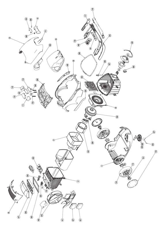
1.1 Exploded view
EN |
Publication number |
599 71 19-22 |
Rev. 01 |
02/2009 |
PR - 4/42 |
Downloaded from www.Manualslib.com manuals search engine

|
Pos |
|
Description |
|
Pos |
|
Description |
|
Pos |
Description |
|
|
|
|
|
||||||
1 |
|
BASE |
23 |
|
HOSE CONNECTION INNER |
46 |
CLIP PARKING |
|||
|
|
|
|
|
|
|
|
|||
2 |
|
MOTOR HOUSING |
24 |
|
BUTTON FRONT COVER |
47 |
ABSORBER FILTER LID |
|||
|
|
|
|
|
|
|
|
|||
3 |
|
FRONT COVER |
25 |
|
CORDWINDER LEVER |
48 |
FRAME HOSE CONNECTION |
|||
|
|
|
|
|
|
|
|
|||
4 |
|
BUTTON FRONT LID |
26 |
|
DISPLAY BASE |
49 |
SIDE FRAME LEFT |
|||
|
|
|
|
|
|
|
|
|||
5 |
|
FRONT LID |
27 |
|
FRONT WHEEL ROLL COMPLETE SOFT |
50 |
PCB CONTROL UNIT |
|||
|
|
|
|
|
|
|
|
|||
6 |
|
REAR COVER |
28 |
|
FRONT WHEEL HOLDER |
51 |
POWER SUPPLY UNIT AEROPRO |
|||
|
|
|
|
|
|
|
|
|||
7 |
|
MOTOR COVER |
29 |
|
SUSPENSION BLOCK DOMEL |
52 |
SHAFT FRONT WHEEL ROLL |
|||
|
|
|
|
|
|
|
|
|||
8 |
|
FILTER LID |
30 |
|
FILTER HOLDER DISASTER FILTER |
53 |
SHAFT FRONT WHEEL HOLDER |
|||
|
|
|
|
|
|
|
|
|||
9 |
|
SUSPENSION RING |
31 |
|
BEARING REAR WHEEL |
54 |
CORDWINDER |
|||
|
|
|
|
|
|
|
|
|||
10 |
|
DISPLAY WINDOW |
32 |
|
SHAFT REAR WHEEL |
56 |
FILTER HEPA |
|||
|
|
|
|
|
|
|
|
|||
11 |
|
PEDAL CW |
33 |
|
LEVER ON-OFF |
57 |
POWER MODULE PCB |
|||
|
|
|
|
|
|
|
|
|||
12 |
|
PEDAL ON/OFF |
34 |
|
BUMPER RIGHT HANDLE |
59 |
MOTOR FAN UNIT |
|||
|
|
|
|
|
|
|
|
|||
13 |
|
BUTTON MIN/MAX |
35 |
|
SEALING HEPA FILTER |
63 |
MULTITOOL |
|||
|
|
|
|
|
|
|
|
|||
14 |
|
REAR WHEEL |
36 |
|
NO BAG SAFETY DEVICE |
65 |
PCB AUTOFUNCTION |
|||
|
|
|
|
|
|
|
|
|||
15 |
|
REAR WHEEL COMPLETE |
38 |
|
ABSORBER MOTOR HOUSING |
66 |
SPRING FRONT COVER BUTTON |
|||
|
|
|
|
|
|
|
|
|||
16 |
|
REAR WHEEL COVER |
39 |
|
SEALING FRONT LID |
67 |
SPRING NO BAG SAFETY DEVICE |
|||
|
|
|
|
|
|
|
|
|||
17 |
|
BUMPER LEFT HANDLE |
40 |
|
ABSORBER MOTOR COVER |
68 |
SPRING BUTTON FRONT LID |
|||
|
|
|
|
|
|
|
|
|||
18 |
|
BUMPER HANDLE UPPER |
41 |
|
FIXATION CORDWINDER |
69 |
SPRING CONTROL PEDALS |
|||
|
|
|
|
|
|
|
|
|||
19 |
|
HANDLE TRANSPARENT |
42 |
|
COVER CORDWINDER |
70 |
SPRING BUTTON POWER REGULATOR |
|||
|
|
|
|
|
|
|
|
|||
20 |
|
SIDE FRAME RIGHT |
43 |
|
COVER MIN/MAX |
71 |
SPRING FRONT COVER POP-UP |
|||
|
|
|
|
|
|
|
|
|||
21 |
|
HOSE CONNECTION OUTER |
44 |
|
HOLDER AEROPRO CONTACT PLATE |
72 |
SPRING cord winder |
|||
|
|
|
|
|
|
|
|
|||
22 |
|
DUST COMPARTMENT |
45 |
|
GRIP HANDLE |
73 |
SPRING Spring cw lever |
|||
|
|
|
|
|
|
|
|
|
|
|
EN |
Publication number |
599 71 19-22 |
Rev. 01 |
02/2009 |
PR - 5/42 |
Downloaded from www.Manualslib.com manuals search engine
2 ACCESSIBILITY
The following chapter follows a disassembling process that step by step will allow the Technician to completely dismount the vacuum cleaner. Tags have been added to help finding quickly the needed item to be removed quickly.
The following sections are outlined:
-Dust bag cover and compartment
-Display cover
-PCB Display/Switch
-Top cover
-Housing
-Cord winder
-Handle
-Wheels
-Power module and power supply unit Aeropro
-Motor
-HBTN
ATTENTION:
Boards and electronic devices could be damaged by electrostatic discharges. Don’t touch any components without any ESD protection.
EN |
Publication number |
599 71 19-22 |
Rev. 01 |
02/2009 |
PR - 6/42 |
Downloaded from www.Manualslib.com manuals search engine

Dust bag cover and compartment
Release the two rear tabs of the grill filter
Completely detach the grill filter |
|
Remove the sponge |
|
|
|
Remove the Hepa filter |
|
Press the lock covers |
|
|
|
Open the dust bag cover |
|
Lift up the lock cover of the lid |
|
|
|
EN |
Publication number |
599 71 19-22 |
Rev. 01 |
02/2009 |
PR - 7/42 |
Downloaded from www.Manualslib.com manuals search engine

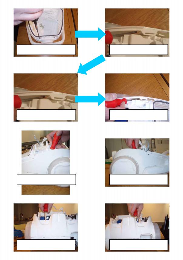
Release the right anchor of the dust bag cover
Detach the lock using a fine-tipped screwdriver
Remove completely the part
Detach the lock using a fine-tipped screwdriver
Release the left anchor
Carefully detach this part
Remove the spring
Carefully detach this part
EN |
Publication number |
599 71 19-22 |
Rev. 01 |
02/2009 |
PR - 8/42 |
Downloaded from www.Manualslib.com manuals search engine

Release the anchor and remove the lid accessory
Release the right anchor of the lid accessory
Remove the spring from the dust bag cover
EN |
Publication number |
599 71 19-22 |
Rev. 01 |
02/2009 |
PR - 9/42 |
Downloaded from www.Manualslib.com manuals search engine

Display cover
Detach the side cover using a finetipped screwdriver
Detach the side cover using a finetipped screwdriver
Lift up the display cover
Remove completely the display cover |
|
Detach the ON/OFF button lever |
|
|
|
Detach the ON/OFF button using a fine-tipped screwdriver
Detach the cord winder button using a fine-tipped screwdriver
EN |
Publication number |
599 71 19-22 |
Rev. 01 |
02/2009 |
PR - 10/42 |
Downloaded from www.Manualslib.com manuals search engine
Remove the springs from the buttons
Detach from the inside the power button using a fine-tipped screwdriver
Detach from the outside the power button using a fine-tipped screwdriver
Remove completely the power button
EN |
Publication number |
599 71 19-22 |
Rev. 01 |
02/2009 |
PR - 11/42 |
Downloaded from www.Manualslib.com manuals search engine

PCB Display/Switch
Detach the pressostat hose
|
|
Remove the PCB with the |
Detach the PCB supply cable |
|
reflector on it |
|
|
|
Detach the reflector tab from the board using a fine-tipped screwdriver
ATTENTION:
Boards and electronic devices could be damaged by electrostatic discharges. Don’t touch any components without any ESD protection.
Detach the reflector tab from the board using a fine-tipped screwdriver
EN |
Publication number |
599 71 19-22 |
Rev. 01 |
02/2009 |
PR - 12/42 |
Downloaded from www.Manualslib.com manuals search engine
Top cover
Remove the screws that fix the top cover
Detach the top cover using a finetipped screwdriver
Detach the top cover using a finetipped screwdriver
Detach the top cover using a finetipped screwdriver
Detach the top cover using a finetipped screwdriver
Detach the top cover using a finetipped screwdriver
Detach the top cover using a finetipped screwdriver
Detach the top cover using a finetipped screwdriver
EN |
Publication number |
599 71 19-22 |
Rev. 01 |
02/2009 |
PR - 13/42 |
Downloaded from www.Manualslib.com manuals search engine
 Loading...