


Anleitung BG_BC_41_43_SPK1:_ 07.03.2008 10:16 Uhr Seite 1
Bedienungsanleitung Benzin-Motorsense
Operating Instructions
Petrol Power Scythe
Mode dʼemploi de la débroussailleuse à moteur à essence
Betjeningsvejledning
Benzindrevet motorle
Használati utasítás Benzín-motorkasza
Bf Upute za uporabu
Kosa s benzinskim motorom
4Uputstva za upotrebu
Kosa s benzinskim motorom
jNávod k použití Benzínová motorová kosa
WNávod na obsluhu motorovej kosy
Art.-Nr.: 34.017.40 |
I.-Nr.: 01017 |
Art.-Nr.: 34.017.50 |
I.-Nr.: 01017 |
BG-BC
BG-BC
41
43

Anleitung BG_BC_41_43_SPK1:_ 07.03.2008 10:16 Uhr Seite 2
Vor Inbetriebnahme Bedienungsanleitung und Sicherheitshinweise lesen und beachten
Read and follow the operating instructions and safety information before using for the first time.
Avant la mise en service, lisez le mode dʼemploi et les consignes de sécurité et respectez-les.
Prima della messa in esercizio leggete e osservate le istruzioni per lʼuso e le avvertenze di sicurezza.
Betjeningsvejledningen og sikkerhedsanvisningerne skal læses, inden maskinen tages i brug. Alle anvisninger skal følges.
Üzembehelyezés előtt elolvasni és figyelembe venni a használati utasítást és a biztonsági utasításokat.
Bf Prije puštanja u rad pročitajte i pridržavajte se ovih uputa za uporabu i sigurnosnih napomena.
4Prije puštanja u pogon pročitajte i uvažite uputstva za upotrebu i napomene bezbednosti.
jPřed uvedením do provozu si přečíst návod k obsluze a bezpečnostní předpisy a oboje dodržovat.
WPred uvedením do prevádzky si prečítajte a dodržiavajte návod na obsluhu a bezpečnostné pokyny.
2
Anleitung BG_BC_41_43_SPK1:_ 07.03.2008 10:16 Uhr Seite 3
A
12
11
15
13
10
16
514
6
9
7
8
17
1
2
3
4
B |
C |
24 |
|
2 |
|
1
20 21
18
3 |
19 |
22 |
23 |
3
Anleitung BG_BC_41_43_SPK1:_ 07.03.2008 10:16 Uhr Seite 4
D1 |
E1 |
26 |
F1 |
F4 |
4
D2 |
E2 |
F2 |
F5 |
D3 |
E3 |
26 |
27 |
4 |
F3 |
|
|
F6 |
|
|
|
|
A |
B
Anleitung BG_BC_41_43_SPK1:_ 07.03.2008 10:16 Uhr Seite 5
F7 |
F8 |
G1 |
G2 |
G4 |
G5 |
H |
I1 |
F9 |
G3 |
G6 |
I2 |
5

Anleitung BG_BC_41_43_SPK1:_ 07.03.2008 10:16 Uhr Seite 6
I3 |
I4 |
I5 |
J1 |
K1 |
L2 |
|
2 |
1 |
6 |
|
J2 |
K2 |
L3 |
J3 |
L1 |
L4
Anleitung BG_BC_41_43_SPK1:_ 07.03.2008 10:16 Uhr Seite 7
L5 |
L6 |
M2 |
3 |
M3 |
4 |
M1 |
|
1 |
2 |
M4 |
5 |
|
7

Anleitung BG_BC_41_43_SPK1:_ 07.03.2008 10:16 Uhr Seite 8
D
Inhaltsverzeichnis
1.Sicherheitshinweise
2.Gerätebeschreibung und Lieferumfang
3.Bestimmungsgemäße Verwendung
4.Technische Daten
5.Montage
6.Vor Inbetriebnahme
7.Bedienung
8.Reinigung, Wartung und Ersatzteilbestellung
9.Entsorgung und Wiederverwertung
10.Fehlerbehebung
8

Anleitung BG_BC_41_43_SPK1:_ 07.03.2008 10:16 Uhr Seite 9
Achtung!
Beim Benutzen von Geräten müssen einige
Sicherheitsvorkehrungen eingehalten werden, um Verletzungen und Schäden zu verhindern. Lesen Sie diese Bedienungsanleitung / Sicherheitshinweise deshalb sorgfältig durch. Bewahren Sie diese gut auf, damit Ihnen die Informationen jederzeit zur
Verfügung stehen. Falls Sie das Gerät an andere Personen übergeben sollten, händigen Sie diese Bedienungsanleitung / Sicherheitshinweise bitte mit aus. Wir übernehmen keine Haftung für Unfälle oder
Schäden, die durch Nichtbeachten dieser Anleitung und den Sicherheitshinweisen entstehen.
1. Sicherheitshinweise
Die entsprechenden Sicherheitshinweise finden Sie im beiliegenden Heftchen!
WARNUNG
Lesen Sie alle Sicherheitshinweise und Anweisungen. Versäumnisse bei der Einhaltung der Sicherheitshinweise und Anweisungen können elektrischen Schlag, Brand und/oder schwere
Verletzungen verursachen.
Bewahren Sie alle Sicherheitshinweise und Anweisungen für die Zukunft auf.
Sicherheitsvorrichtungen
Beim Arbeiten mit dem Gerät muss die entsprechende Kunststoffschutzhaube für Messeroder Fadenbetrieb montiert sein, um das
Wegschleudern von Gegenständen zu verhindern. Das integrierte Messer in der SchnittfadenSchutzhaube schneidet den Faden automatisch auf die optimale Länge ab.
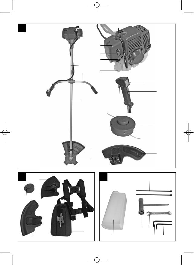
2.Gerätebeschreibung und Lieferumfang (Abb. A-C)
1.Fadenspule mit Schnittfaden
2.Schutzhaube für Schnittmesser
3.Schutzhaube für Schnittfaden
4.Schnittmesser
5.Führungshandgriff
6.Schalter Motor „Ein/Aus“
7.Gashebelsperre
8.Gashebel
9.“Arretierung” Gashebel
10.Choke-Hebel
11.Startseilzug
12.Zündkerzenstecker
13.Abdeckung Luftfiltergehäuse
D
14.Benzintank
15.Gehäuse für Motorkühlung
16.Kraftstoffpumpe „Primer“
17.Führungsholm mit Antriebswelle
18.Tragegurt
19.Öl/Benzin Mischflasche
20.Zündkerzenschlüssel
21.Gabelschlüssel SW 8/SW 10
22.Innensechskantschlüssel Gr. 4
23.Innensechskantschlüssel Gr. 6
24.2 Kabelbinder
3. Bestimmungsgemäße Verwendung
Das Gerät ist zum Schneiden von Rasen und
Grasflächen geeignet. Die Einhaltung der vom Hersteller beigefügten Gebrauchsanweisung ist Vorraussetzung für den ordnungsgemäßen Gebrauch des Gerätes. Jede andere Verwendung, die in dieser Anleitung nicht ausdrücklich zugelassen wird, kann zu Schäden am Gerät führen und eine ernsthafte Gefahr für den Benutzer darstellen. Beachten Sie unbedingt die Einschränkungen in den Sicherheitshinweisen.
Bitte beachten Sie, dass unsere Geräte bestimmungsgemäß nicht für den gewerblichen, handwerklichen oder industriellen Einsatz konstruiert wurden. Wir übernehmen keine Gewährleistung, wenn das Gerät in Gewerbe-, Handwerksoder
Industriebetrieben sowie bei gleichzusetzenden Tätigkeiten eingesetzt wird.
Achtung! Wegen körperlicher Gefährdung des
Benutzers darf die Benzinmotorsense nicht zu folgenden Arbeiten eingesetzt werden: zum Reinigen von Gehwegen und als Häcksler zum Zerkleinern von Baumund Heckenabschnitten. Ferner darf die Benzinmotorsense nicht zum Einebnen von
Bodenerhebungen, wie z.B. Maulwurfshügel verwendet werden. Aus Sicherheitsgründen darf die
Benzinmotorsense nicht als Antriebsaggregat für andere Arbeitswerkzeuge und Werkzeugsätze jeglicher Art verwendet werden.
Die Maschine darf nur nach ihrer Bestimmung verwendet werden. Jede weitere darüber hinausgehende Verwendung ist nicht bestimmungsgemäß. Für daraus hervorgerufene
Schäden oder Verletzungen aller Art haftet der Benutzer/Bediener und nicht der Hersteller.
9

Anleitung BG_BC_41_43_SPK1:_ 07.03.2008 10:16 Uhr Seite 10
D
4. Technische Daten
BG-BC 43
Motortyp |
2-Takt-Motor, luftgekühlt, Chromzylinder |
BG-BC 41 |
|
|
|
|
Motorleistung (max.) |
1,45 kW/ 2,0 PS |
||
Motortyp |
2-Takt-Motor, luftgekühlt, Chromzylinder |
|
|
|
|
|
||
|
Hubraum |
|
|
42,7 ccm |
||||
|
|
|
|
|
|
|||
Motorleistung (max.) |
|
1,4 kW/ 1,9 PS |
|
|
|
|||
|
|
Leerlaufdrehzahl Motor |
2800+/-200 min-1 |
|||||
Hubraum |
|
|
40,6 ccm |
|
|
|
|
|
|
|
|
Max. Drehzahl Motor |
|
|
|||
|
|
|
|
|
|
|
||
Leerlaufdrehzahl Motor |
2800+/-200 min-1 |
|
Sense: |
|
|
9000 min-1 |
||
Max. Drehzahl Motor |
|
|
|
Trimmer: |
|
|
8400 min-1 |
|
Sense: |
|
|
9000 min-1 |
|
|
|
|
|
|
|
|
Max. Drehzahl Doppelfaden |
|
|
|||
Trimmer: |
|
|
8400 min-1 |
|
Sense: |
|
|
6750 min-1 |
Max. Drehzahl Doppelfaden |
|
|
|
Trimmer: |
|
|
6300 min-1 |
|
Sense: |
|
|
6750 min-1 |
|
|
|
|
|
|
|
|
Zündung |
|
|
Elektronisch |
||
Trimmer: |
|
|
6300 min-1 |
|
|
|
|
|
|
|
|
Antrieb |
|
Zentrifugalkupplung |
|||
|
|
|
|
|
|
|
|
|
Zündung |
|
|
Elektronisch |
|
|
|
|
|
|
|
|
Gewicht (leerer Tank) |
|
7,0 kg |
|||
|
|
|
|
|
|
|
||
Antrieb |
|
Zentrifugalkupplung |
|
|
|
|
||
|
|
Länge Führungsholm |
|
150 cm |
||||
|
|
|
|
|
|
|
||
Gewicht (leerer Tank) |
|
7,0 kg |
|
|
|
|
||
|
|
Schnittkreis-Faden Ø |
|
41 cm |
||||
|
|
|
|
|
|
|
||
Länge Führungsholm |
|
150 cm |
|
|
|
|
||
|
|
Schnittkreis-Messer Ø |
|
23 cm |
||||
|
|
|
|
|
|
|
|
|
Schnittkreis-Faden Ø |
|
41 cm |
|
|
|
|
|
|
|
|
Fadenlänge |
|
|
8,0 m |
|||
|
|
|
|
|
|
|
|
|
Schnittkreis-Messer Ø |
|
23 cm |
|
|
|
|
|
|
|
|
Faden-Ø |
|
|
2,0 mm |
|||
|
|
|
|
|
|
|
|
|
Fadenlänge |
|
|
8,0 m |
|
|
|
|
|
|
|
|
Tankinhalt |
|
|
0,8 l |
||
|
|
|
|
|
|
|
||
Faden-Ø |
|
|
2,0 mm |
|
|
|
||
|
|
|
Zündkerze |
NGK BPMR7A / Champion RCJ6Y/ |
||||
|
|
|
|
|
|
|
|
|
Tankinhalt |
|
|
0,8 l |
|
|
|
|
LDL7T / L8RTF |
|
|
|
|
|||||
Zündkerze |
NGK BPMR7A / Champion RCJ6Y/ |
|
|
|||||
|
Kraftstoffverbrauch (In Übereinstimung mit ISO 8893) |
|||||||
|
|
|
LDL7T / L8RTF |
|
bei max. Motorleistung |
|
0,9 kg/h |
|
|
|
|
||||||
Kraftstoffverbrauch (In Übereinstimung mit ISO 8893) |
|
|
||||||
|
Spezifischer Kraftstoffverbrauch (In Übereinstimung |
|||||||
bei max. Motorleistung |
|
0,8 kg/h |
|
mit ISO 8893) bei max. Motorleistung |
536 g/kWh |
|||
|
|
|
|
|
|
|||
Spezifischer Kraftstoffverbrauch (In Übereinstimung |
|
|
|
|
|
|||
|
Vibration ahv |
|
|
|
||||
mit ISO 8893) bei max. Motorleistung |
457 g/kWh |
|
Leerlauf (max.) |
|
|
5,1 m/s2 |
||
Vibration ahv |
|
|
|
|
Betrieb (max.) |
|
|
7,4 m/s2 |
Leerlauf (max.) |
|
6,8 m/s2 |
|
|
|
|
||
|
|
Schalldruckpegel LpA |
|
|
||||
Betrieb (max.) |
|
7,2 m/s2 |
|
Leerlauf (max.) |
|
|
77 dB (A) |
|
|
|
|
|
|
|
|
|
|
Schalldruckpegel LpA |
|
|
|
Betrieb (max.) |
|
|
100 dB (A) |
|
Leerlauf (max.) |
|
84 dB (A) |
|
|
|
|
||
|
|
Schallleistungspegel LpA |
|
|
||||
Betrieb (max.) |
|
104 dB (A) |
|
Leerlauf (max.) |
|
|
97 dB (A) |
|
|
|
|
|
|
|
|
|
|
Schallleistungspegel LpA |
|
|
|
Betrieb (max.) |
|
|
114 dB (A) |
|
Leerlauf (max.) |
|
102 dB (A) |
|
|
|
|
|
|
|
|
Geräusch und Vibration wurde nach EN ISO 11806 |
||||||
Betrieb (max.) |
|
114 dB (A) |
|
|||||
|
|
gemessen. |
|
|
|
|||
|
|
|
|
|
|
|
|
|
|
|
|
|
|
|
|
||
10
Anleitung BG_BC_41_43_SPK1:_ 07.03.2008 10:16 Uhr Seite 11
5. Montage
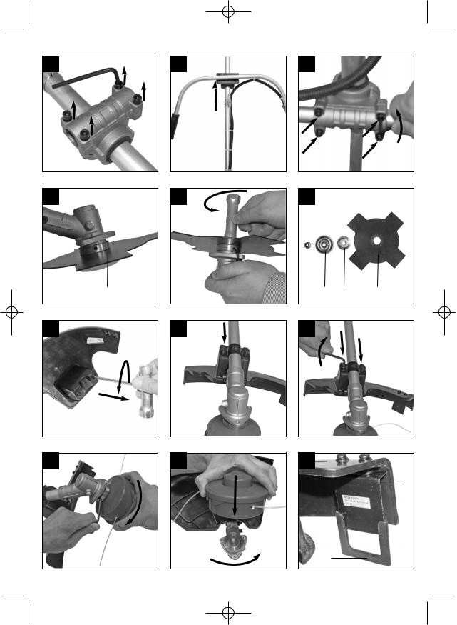
5.1Montage des Führungshandgriffes
Montieren Sie den Führungshandgriff wie in den Abbildungen D1 – D3 dargestellt. Ziehen Sie die
Schrauben erst dann ganz fest, wenn Sie die optimale Arbeitsposition mit dem Tragegurt eingestellt haben. Der Führungshandgriff sollte wie in Abbildung A dargestellt ausgerichtet werden.
5.2Montage/Ersetzen des Schnittmessers
(Abb. E1 - E3)
Im Auslieferungszustand ist das Schnittmesser fertig auf dem Gerät montiert. Darum wird zuerst die Demontage erläutert:
Bohrung der Mitnehmerscheibe (Abb. E1/ Pos.
26) und darunter liegende Kerbe überein bringen und Mitnehmerscheibe mit Innensechskantschlüssel Gr. 6 arretieren (Abb. E1/ E2)
Befestigungsmutter des Schnittmessers mit beiliegendem Zündkerzenschlüssel entfernen. (Abb. E2). Achtung: Linksgewinde!
Druckplattenabdeckung (Abb. E3/Pos. 26) und
Druckplatte (Abb. E3/Pos. 27) entfernen.
Das Schnittmesser (Abb. E3/ Pos. 4) kann nun entnommen werden.
Die Montage erfolgt in umgekehrter Reihenfolge. Beachten Sie dass bei der Druckplatte (Abb. E3/Pos. 26) die Seite mit der Vertiefung Richtung
Schnittmesser zeigen muss.
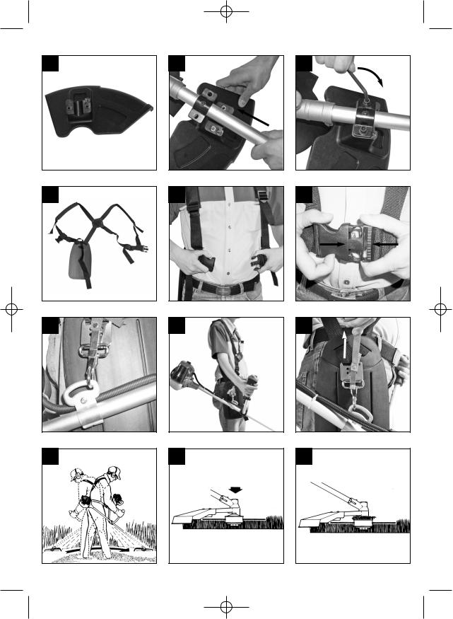
5.3Montage der Schnittfadenschutzhaube Achtung: Beim Arbeiten mit dem Schnittfaden muss die Schnittfaden-Schutzhaube montiert sein.
Die Montage der Schnittfaden-Schutzhaube erfolgt wie in den Abbildungen F1 – F3 dargestellt.
An der Unterseite der Schutzhaube befindet sich ein
Messer (Abb. F6/ Pos. A) für die automatische Fadenlängenregulierung. Dieses ist mit einem
Schutz (Abb. F6/ Pos.B) abgedeckt.
Entfernen Sie diesen Schutz vor Arbeitsbeginn und bringen Sie diesen nach dem Arbeiten wieder an.
5.4Montage/ Ersetzen der Fadenspule
Bohrung der Mitnehmerscheibe und darunter liegende Kerbe überein bringen und Mitnehmerscheibe mit Innensechskantschlüssel Gr.6 arretieren (Abb. F4). Fadenspule auf den Führungsdorn schrauben(Abb. F5).
Achtung: Linksgewinde!
Die Demontage erfolgt in umgekehrter Reihenfolge.
5.5 Montage der Messerschutzhaube
Achtung: Beim Arbeiten mit dem Schnittmesser muss die Schnittmesser-Schutzhaube montiert sein.
D
Die Montage der Schnittmesser-Schutzhaube erfolgt wie in den Abbildungen F7 – F9 dargestellt.
6. Vor Inbetriebnahme
Prüfen Sie vor Inbetriebnahme alle beweglichen Teile auf Leichtgängigkeit. Überprüfen Sie alle Verschraubungen auf festen Sitz und überprüfen Sie sämtliche Schutzvorrichtungen.
6.1 Einstellen der Schnitthöhe
Tragegurt wie in Abbildung G1-G3 dargestellt anlegen.
Das Gerät am Tragegurt einhaken (Abb. G4).
Mit den verschiedenen Gurtverstellern am
Tragegurt optimale Arbeitsund Schnittposition einstellen (Abb. G5).
Um die optimale Tragegurtlänge festzustellen machen Sie anschließend einige
Schwingbewegungen ohne den Motor anzulassen (Abb. H).
Der Tragegurt ist mit einem Schnellöffnungs-
Mechanismus ausgestattet. Ziehen Sie, falls es notwendig ist das Gerät schnell abzulegen, an dem roten Gurtstück (Abb. G6).
Achtung: Benutzen Sie den Gurt immer wenn Sie mit dem Gerät arbeiten. Bringen Sie den Gurt an sobald Sie den Motor gestartet haben und er im
Leerlauf läuft. Schalten Sie den Motor aus bevor Sie den Tragegurt abnehmen.
Prüfen Sie das Gerät vor jeder Inbetriebnahme auf:
Dichtheit des Treibstoffsystems.
Einwandfreien Zustand der Schutzeinrichtungen und der Schnittvorrichtung.
Festen Sitz sämtlicher Verschraubungen.
6.2 Treibstoff und Öl
Empfohlene Treibstoffe
Benutzen Sie nur ein Gemisch aus bleifreiem Benzin und speziellem 2-Takt-Motoröl. Mischen Sie das
Treibstoffgemisch nach der Treibstoff-Mischtabelle an.
Achtung: Verwenden Sie kein Treibstoffgemisch, das mehr als 90 Tage lang gelagert wurde. Achtung: Verwenden Sie kein 2-Takt-Öl das ein
Mischverhältnis von 100:1 empfiehlt. Bei Motorenschäden auf Grund ungenügender
Schmierung entfällt die Motorgarantie des Herstellers.
Achtung: Verwenden Sie zum Transport und zur
Lagerung von Kraftstoff nur dafür vorgesehene und zugelassene Behälter.
11
Anleitung BG_BC_41_43_SPK1:_ 07.03.2008 10:17 Uhr Seite 12
Geben Sie jeweils die richtige Menge Benzin und 2- Takt-Öl in die beiliegende Mischflasche (Siehe aufgedruckte Skala). Schütteln Sie anschließend den Behälter gut durch.
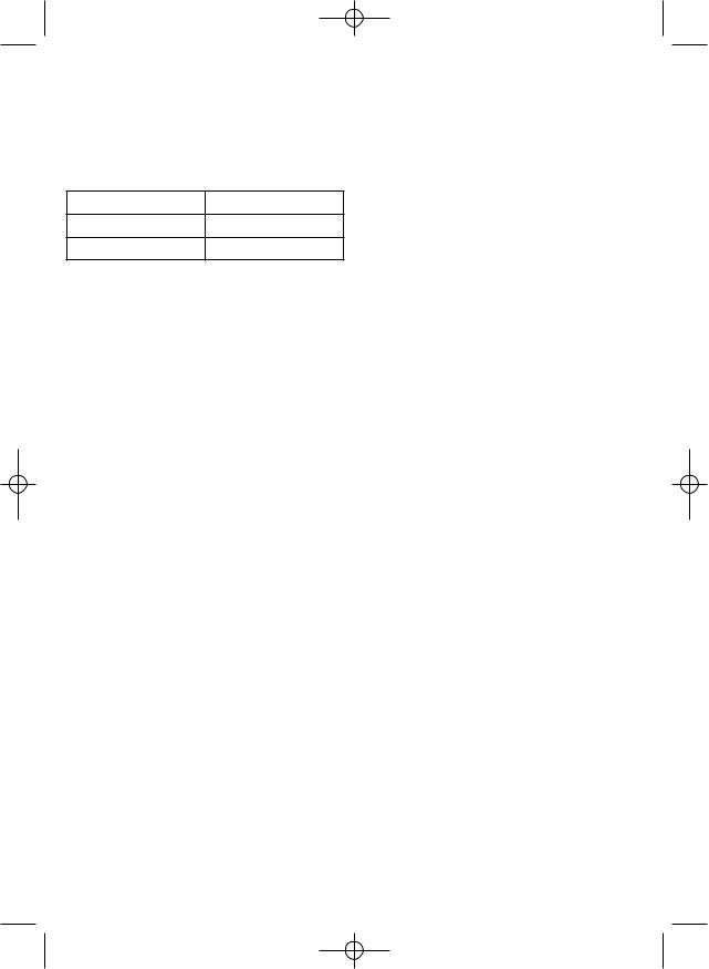
6.3 Treibstoff-Misch-Tabelle
Mischverfahren: 25 Teile Benzin auf 1 Teil Öl
Benzin |
2-Takt-Öl |
1 Liter |
40 ml |
5 Liter |
200 ml |
7. Bedienung
Beachten Sie bitte die gesetzlichen Bestimmungen zur Lärmschutzverordnung, die örtlich unterschiedlich sein können.
7.1 Starten bei kaltem Motor
Füllen Sie den Tank mit einer angemessenen Menge Benzin/Öl-Gemisch. Siehe auch Treibstoff und Öl.
1.Gerät auf eine harte, ebene Fläche stellen.
2.Choke-Hebel (Abb. A/Pos. 10) auf „  “ stellen.
3.Kraftstoffpumpe (Primer) (Abb. A/Pos. 16) 10x drücken.
4.Ein-/ Aus-Schalter (Abb. A/Pos.6) auf „I“ schalten.
5.Gashebel feststellen. Hierzu Gashebelsperre (Abb. A/Pos 7)und anschließend Gashebel (Abb.
A/Pos. 8) betätigen und durch gleichzeitiges Drücken der Arretierung (Abb. A/Pos. 9) den
Gashebel feststellen.
6.Das Gerät gut festhalten und den Startseilzug (Abb. A/Pos. 11) bis zum ersten Widerstand herausziehen. Jetzt den Startseilzug 4x rasch anziehen. Das Gerät sollte starten.
Achtung: Den Startseilzug nicht zurückschleudern lassen. Dies kann zu Beschädigungen führen.
7.Ist der Motor gestartet, den Choke-Hebel sofort auf „  “ stellen und das Gerät ca. 10sek. warmlaufen lassen.
Achtung: Durch den festgestellten Gashebel beginnt das Schnittwerkzeug bei startendem
Motor zu arbeiten.
Anschließend Gashebel durch einfaches
Betätigen entriegeln (Der Motor kehrt in den Leerlauf zurück).
8.Sollte der Motor nicht starten wiederholen Sie die
Schritte 6-7.
Zur Beachtung: Springt der Motor auch nach mehreren Versuchen nicht an, lesen Sie den Abschnitt „Fehlerbehebung am Motor“.
Zur Beachtung: Ziehen Sie den Startseilzug stets
12
gerade heraus. Wird sie in einem Winkel herausgezogen, entsteht Reibung an der Öse. Durch diese Reibung wird die Schnur durchgescheuert und nutzt sich schneller ab. Halten Sie stets den Anlassergriff, wenn sich die Schnur wieder einzieht.
Lassen sie die Schnur nie aus dem ausgezogenen
Zustand zurückschnellen.
7.2 Starten bei warmem Motor
(Das Gerät stand für weniger als 15-20min still)
1.Gerät auf harte, ebene Fläche stellen.
2.Ein-/Aus-Schalter auf „I“ schalten.
3.Gashebel feststellen (analog „Starten bei kaltem Motor“).
4.Gerät gut festhalten und den Startseilzug bis zum ersten Widerstand herausziehen. Jetzt den
Startseilzug rasch anziehen. Das Gerät sollte nach 1-2 Zügen starten. Falls die Maschine nach 6 Zügen immer noch nicht startet wiederholen Sie die Schritte 1-7 unter kalten Motor starten.
7.3 Motor abstellen
Not-Aus Schrittfolge:
Falls es notwendig ist, die Maschine sofort anzuhalten, stellen Sie hierzu den Ein-/Aus-Schalter auf „Stop“ bzw. „0“
Normale Schrittfolge:
Lassen Sie den Gashebel los und warten Sie bis der Motor in Leerlaufgeschwindigkeit übergegangen ist. Stellen Sie dann den Ein-/ Aus-Schalter auf „Stop“ bzw. „0“.
7.4 Arbeitshinweise
Trainieren Sie vor Einsatz des Gerätes sämtliche Arbeitstechniken bei abgestelltem Motor.
Verlängerung des Schnittfadens
Warnung! Benutzen Sie keinen Metalldraht oder kunststoffumhüllten Metalldraht irgendeiner Art in der Fadenspule. Dies kann zu schweren Verletzungen beim Benutzer führen.
Zur Verlängerung des Schnittfadens, lassen Sie den
Motor auf Vollgas laufen und tippen Sie die Fadenspule auf den Boden. Der Faden wird automatisch verlängert. Das Messer am Schutzschild kürzt den Faden auf die zulässige Länge (Abb. I1).
Vorsicht: Entfernen Sie regelmäßig alle Rasenund Unkrautreste um ein Überhitzen des Schaftrohrs zu vermeiden. Rasen-/ Gras-/Unkrautreste verfangen sich unterhalb des Schutzschilds (Abb. I2), dies verhindert eine ausreichende Kühlung des
Schaftrohrs. Entfernen Sie die Reste vorsichtig mit einem Schraubenzieher oder dergleichen.

Anleitung BG_BC_41_43_SPK1:_ 07.03.2008 10:17 Uhr Seite 13
Verschiedene Schnittverfahren
Ist das Gerät richtig montiert, schneidet es Unkraut und hohes Gras an schwer zugänglichen Stellen, wie z.B. entlang von Zäunen, Mauern und Fundamenten sowie um Bäume herum. Es lässt sich auch für
„Abmäharbeiten“ einsetzen, um Vegetation zur besseren Vorbereitung eines Gartens oder zum Ausputzen eines bestimmten Bereiches bodennah zu entfernen.
Zur Beachtung: Auch bei sorgfältiger Anwendung hat das Schneiden an Fundamenten, Steinoder Betonmauern usw. eine über dem Normalen liegende Abnutzung des Fadens zur Folge.
Trimmen/ Mähen
Schwingen Sie den Trimmer in sichelartiger Bewegung von Seite zu Seite. Halten Sie die Fadenspule stets parallel zum Boden. Überprüfen Sie das Gelände und legen Sie die gewünschte
Schnitthöhe fest. Führen und halten Sie die
Fadenspule in der gewünschten Höhe, zwecks gleichmässigem Schnitt (Abb. I3).
Niedriges Trimmen
Halten Sie den Trimmer mit einer leichten Neigung genau vor sich, so dass sich die Unterseite der Fadenspule über dem Boden befindet und der Faden die richtige Schnittstelle trifft. Schneiden Sie immer von sich weg. Ziehen Sie den Trimmer nicht zu sich hin.
Schneiden an Zaun/ Fundament
Nähern Sie sich beim Schneiden langsam
Maschendrahtzäunen, Lattenzäunen, Natursteinmauern und Fundamenten um nah daran zu schneiden, ohne jedoch mit dem Faden gegen das Hindernis zu schlagen. Kommt der Faden z.B. mit Steinen, Steinmauern oder Fundamenten in
Berührung, nutzt er sich ab oder franst aus. Schlägt der Faden gegen Zaungeflecht, bricht er ab.
Trimmen um Bäume
Trimmen Sie um Baumstämme, nähern Sie sich langsam, damit der Faden die Rinde nicht berührt. Gehen Sie um den Baum herum, und schneiden Sie dabei von links nach rechts. Nähern Sie sich Gras oder Unkraut mit der Spitze des Fadens, und kippen Sie die Fadenspule leicht nach vorn.
Warnung: Seien Sie überaus vorsichtig bei Abmäharbeiten. Halten Sie bei solchen Arbeiten einen Abstand von 30 Metern zwischen sich und anderen Personen oder Tieren ein.
Abmähen
Beim Abmähen erfassen Sie die gesamte Vegetation bis zum Grund. Dazu neigen Sie die Fadenspule im 30 Grad Winkel nach rechts. Stellen Sie den
Handgriff in die gewünschte Position. Beachten Sie die erhöhte Verletzungsgefahr des Benutzers, Zuschauer und Tiere, sowie die Gefahr der Sachbeschädigung durch weggeschleuderte Objekte (z.B. Steine) (Abb. I4).
Warnung: Entfernen Sie mit dem Gerät keine Gegenstände von Fußwegen usw.!
Das Gerät ist ein kraftvolles Werkzeug, und kleine Steine oder andere Gegenstände können 15 Meter und mehr weggeschleudert werden und zu
Verletzungen oder Beschädigungen an Autos, Häusern und Fenstern führen.
Sägen
Das Gerät ist nicht zum Sägen geeignet.
Verklemmen
Sollte das Schnittmesser wegen zu dichter Vegetation blockieren stellen Sie unverzüglich den
Motor ab. Befreien Sie das Gerät von Gras und
Gestrüpp bevor Sie es erneut in Betrieb nehmen.
Vermeiden von Rückschlag
Beim Arbeiten mit dem Schnittmesser besteht die
Gefahr des Rückschlages wenn dieses auf feste Hindernisse (Baumstamm, Ast, Baumstumpf, Stein oder dergleichen) trifft. Das Gerät wird dabei gegen die Drehrichtung des Werkzeugs zurückgeschleudert. Dies kann zum Verlust der Kontrolle über das
Gerät führen. Benutzen Sie das Schnittmesser nicht in der Nähe von Zäunen, Metallpfosten, Grenzsteinen oder Fundamenten.
Zum Schneiden von dichten Stängeln positionieren Sie diese wie in Abb. I5 dargestellt um Rückschläge zu vermeiden.
8.Reinigung, Wartung und Ersatzteilbestellung
Schalten Sie das Gerät vor Wartungsarbeiten immer aus und ziehen Sie den Zündkerzenstecker ab.
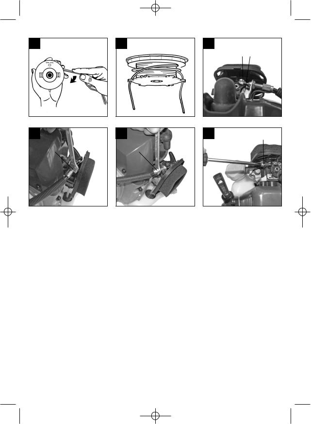
8.1 Ersetzen von Fadenspule/Schnittfaden
1.Fadenspulen-Gehäuse unterhalb der beiden
Haltenasen (Abb. L2/ Pos. 1) zusammendrücken (Abb. L1) und Fadenspulen-Deckel abnehmen (Abb. L2/Pos. 2).
2.Fadenspule aus dem Fadenspulen-Gehäuse entnehmen (Abb. L3). Achten Sie darauf dass
13

Anleitung BG_BC_41_43_SPK1:_ 07.03.2008 10:17 Uhr Seite 14
D
die Feder und die Beilagscheiben nicht verloren gehen.
3.Evtl. noch vorhandenen Schnittfaden entfernen.
4.Neuen Schnittfaden in der Mitte zusammenlegen und die entstandene Schlaufe in die Aussparung des Spulenteilers einhängen. (Abb. L4)
5.Faden unter Spannung gegen den Uhrzeigersinn aufwickeln. Der Spulenteiler trennt dabei die beiden Hälften des Nylonfadens. (Abb. L5)
6.Die letzten 15cm der beiden Fadenenden in die gegenüberliegenden Fadenhalter der Fadenspule einhaken. (Abb. L6)
7.Die beiden Fadenenden durch die Metallösen im Fadenspulen-Gehäuse führen (Abb. L3).
8.Fadenspule in das Fadenspulen-Gehäuse drücken. Achten Sie darauf dass Feder und Beilagscheiben in der richtigen Position sind. (Abb. L3)
9.Fadenspulen-Deckel auf das Fadenspulen-
Gehäuse drücken. Achten Sie darauf dass die beiden Haltenasen (Abb. L2/Pos. 1) im Fadenspulen-Gehäuse in die entsprechenden Aussparungen (Abb. L2/Pos. 2) im FadenspulenDeckel einrasten.
10.Kurz und kräftig an beiden Fadenenden ziehen um diese aus den Fadenhaltern der Fadenspule zu lösen.
11.Überschüssigen Faden auf etwa 13cm zurückschneiden. Das verringert die Belastung auf den Motor während des Startens und Aufwärmens.
12.Fadenspule wieder montieren Siehe Punkt 5.4. Wird die komplette Fadenspule erneuert sind die
Punkte 3-6 zu überspringen.
8.2 Wartung des Luftfilters (Abb. J1 – J3)
Verschmutzte Luftfilter verringern die Motorleistung durch zu geringe Luftzufuhr zum Vergaser.
Regelmäßige Kontrolle ist daher unerlässlich. Der Luftfilter sollte alle 25 Betriebsstunden kontrolliert werden und bei Bedarf gereinigt werden. Bei sehr staubiger Luft ist der Luftfilter häufiger zu überprüfen.
1.Entfernen Sie den Luftfilterdeckel (Abb. J1 – J2)
2.Entnehmen sie das Filterelement (Abb. J3)
3.Reinigen Sie das Filterelement durch ausklopfen oder ausblasen.
4.Der Zusammenbau erfolgt in umgekehrter Reihenfolge.
Achtung: Luftfilter nie mit Benzin oder brennbaren Lösungsmitteln reinigen.
14
8.3Wartung der Zündkerze (Abb. K1 – K2)
Zündkerzenfunkenstrecke = 0,6mm. Ziehen Sie die Zündkerze mit 12 bis 15 Nm an. Überprüfen Sie die Zündkerze erstmals nach 10 Betriebsstunden auf
Verschmutzung und reinigen Sie diese gegebenenfalls mit einer Kupferdrahtbürste. Danach die Zündkerze alle 50 Betriebsstunden warten.
1. Ziehen Sie den Zündkerzenstecker (Abb. K1) mit einer Drehbewegung ab.
2. Entfernen Sie die Zündkerze (Abb. K2) mit dem beiliegenden Zündkerzenschlüssel.
3. Der Zusammenbau erfolgt in umgekehrter Reihenfolge.
8.4Schleifen des Schutzhaubenmessers
Das Schutzhaubenmesser (Abb. F6/Pos. A) kann mit der Zeit stumpf werden. Sollten Sie dies feststellen, lösen Sie die 2 Schrauben mit denen das
Schutzhaubenmesser an der Schutzhaube befestigt ist. Befestigen Sie das Messer in einem Schraubstock. Schleifen Sie das Messer mit einer Flachfeile und achten Sie darauf, den Winkel der Schnittkante beizubehalten. Feilen Sie nur in eine
Richtung.
8.5 Vergaser Einstellungen
Achtung! Einstellungen am Vergaser dürfen nur durch autorisierten Kundendienst vorgenommen werden.
Zu allen Arbeiten am Vergaser muss zuerst die Luftfilterabdeckung wie in Abbildung J1 und J2 gezeigt demontiert werden.
Einstellen des Gasseilzuges:
Sollte die Maximaldrehzahl des Geräts mit der Zeit nicht mehr erreicht werden und sämtliche anderen
Ursachen nach Abschnitt 10 Fehlerbehebung ausgeschlossen sein, könnte eine Einstellung des
Gasseilzuges erforderlich sein.
Überprüfen Sie hierfür zunächst ob der Vergaser bei voll durchgedrücktem Gasgriff ganz öffnet. Dies ist der Fall wenn der Vergaserschieber (Abb. M1/Pos. 1) bei voll betätigtem Gas am Anschlag (Abb.
M1/Pos. 2) anliegt. Abbildung M1 zeigt die korrekte Einstellung. Sollte der Vergaserschieber den Anschlag nicht berühren ist eine Nachjustierung notwendig.
Um den Gasseilzug nachzustellen sind folgende
Schritte erforderlich:
Lösen Sie die Kontermutter (Abb. M2/Pos. 3) einige Umdrehungen.
Drehen Sie die Verstellschraube (Abb.
M3/Pos.4) heraus, bis der Vergaserschieber bei voll betätigtem Gas, wie in Abbildung M1 gezeigt, am Anschlag anliegt.

Anleitung BG_BC_41_43_SPK1:_ 07.03.2008 10:17 Uhr Seite 15
Ziehen Sie die Kontermutter wieder fest.
Einstellen des Standgases:
Achtung! Standgas bei warmen Betriebszustand einstellen.
Sollte das Gerät bei nicht betätigtem Gashebel ausgehen und sämtliche anderen Ursachen nach Abschnitt 10 Fehlerbehebung ausgeschlossen sein, ist ein Nachjustieren des Standgases notwendig.
Drehen Sie hierzu die Standgasschraube (Abb.
M4/Pos. 5) im Uhrzeigersinn bis das Gerät im Leerlauf sicher läuft.
Sollte das Standgas so hoch sein, dass sich das Schnittwerkzeug mitdreht, muss dies durch
Linksdrehen der Standgasschraube (Abb. M4/ Pos.
5) soweit verringert werden bis sich das Schnittwerkzeug nicht mehr mitdreht.
8.6 Umweltschutz
Verschmutztes Wartungsmaterial und Betriebsstoffe in einer dafür vorgesehenen Sammelstelle abgeben. Verpackungsmaterial, Metall und Kunststoffe dem Recycling zuführen.
8.7 Lagerung
Achtung: Ein Fehler bei der Befolgung dieser Schritte kann zur Folge haben, dass sich Ablagerungen an der Vergaserinnenwand bilden, was ein erschwertes Anlassen oder einen dauerhaften Schaden an der Maschine zu Folge haben kann.
1.Führen Sie alle allgemeinen Wartungsarbeiten durch, welche im Abschnitt Wartung in der Bedienungsanleitung stehen.
2.Lassen Sie den Treibstoff aus dem Tank ab (Benutzen Sie hierzu eine handelsübliche Kunststoff-Benzinpumpe aus dem Baumarkt).
3.Nachdem der Treibstoff abgelassen ist, starten Sie die Maschine.
4.Lassen Sie die Maschine im Leerlauf weiterlaufen bis sie stoppt. Das reinigt den Vergaser vom restlichen Treibstoff.
5.Lassen Sie die Maschine abkühlen.(ca. 5 Minuten)
6.Entfernen Sie die Zündkerze.
7.Füllen Sie eine Teelöffel große Menge 2-Takt Motoröl in die Feuerungskammer. Ziehen Sie einige male vorsichtig den Startseilzug heraus, um die inneren Bauteile mit dem Öl zu benetzen.
Setzen Sie die Zündkerze wieder ein.
8.Säubern Sie das äußere Gehäuse der Maschine.
9.Bewahren Sie die Maschine an einem kalten, trockenen Platz außerhalb der Reichweite von Zündquellen und brennbaren Substanzen auf.
Düngemittel oder andere chemische Gartenprodukte beinhalten häufig Substanzen, welche die Korrosion von Metallen
D
beschleunigen. Lagern Sie die Maschine nicht auf oder in der Nähe von Düngmittel oder anderen Chemikalien.
Wiederinbetriebnahme
1.Entfernen Sie die Zündkerze.
2.Ziehen Sie den Startseilzug mehrmals heraus um die Feuerungskammer von Ölrückständen zu reinigen.
3.Säubern Sie die Zündkerzenkontakte oder setzen Sie eine neue Zündkerze ein.
4.Füllen Sie den Tank. Siehe Abschnitt Treibstoff und Öl.
5.Führen Sie die Schritte 1-7 unter Punkt „Starten bei Kaltem Motor“ durch.
8.8 Transport
Wenn Sie das Gerät transportieren möchten entleeren Sie den Benzintank wie im Kapitel „Lagerung“ erklärt. Reinigen Sie das Gerät mit einer Bürste oder einem Handfeger von grobem Schmutz.
Demontieren Sie den Führungshandgriff wie unter
Punkt 5.1 erklärt.
8.9 Ersatzteilbestellung:
Bei der Ersatzteilbestellung sollten folgende
Angaben gemacht werden;
Typ des Gerätes
Artikelnummer des Gerätes
Ident-Nummer des Gerätes
Ersatzteilnummer des erforderlichen Ersatzteils
Aktuelle Preise und Infos finden Sie unter www.isc-gmbh.info
9. Entsorgung und Wiederverwertung
Das Gerät befindet sich in einer Verpackung um Transportschäden zu verhindern. Diese Verpackung ist Rohstoff und ist somit wieder verwendbar oder kann dem Rohstoffkreislauf zurückgeführt werden.
Das Gerät und dessen Zubehör bestehen aus verschiedenen Materialien, wie z.B. Metall und Kunststoffe. Führen Sie defekte Bauteile der
Sondermüllentsorgung zu. Fragen Sie im Fachgeschäft oder in der Gemeindeverwaltung nach!
15

Anleitung BG_BC_41_43_SPK1:_ 07.03.2008 10:17 Uhr Seite 16
D
10. Fehlerbehebung
Störung |
Mögliche Ursache |
Störungsbehebung |
||
Das Gerät springt nicht an. |
Fehlerhaftes Vorgehen beim |
Folgen Sie den Anweisungen zum |
||
|
Starten. |
Starten |
||
|
Verrußte oder feuchte Zündkerze |
Zündkerze reinigen oder durch |
||
|
|
neue ersetzen. |
||
|
Falsche Vergasereinstellung |
Autorisierten Kundendienst |
||
|
|
aufsuchen, oder das Gerät an die |
||
|
|
ISC-GmbH senden. |
||
Das Gerät springt an, hat aber nicht |
Falsche Einstellung des |
Chokehebel auf „ |
|
“ stellen. |
|
||||
die volle Leistung. |
Chokehebels |
|
|
|
|
|
|
||
|
Verschmutzter Luftfilter |
Luffilter reinigen |
||
|
|
|
||
|
Falsche Vergasereinstellung |
Autorisierten Kundendienst |
||
|
|
aufsuchen, oder das Gerät an die |
||
|
|
ISC-GmbH senden. |
||
Der Motor läuft unregelmäßig |
Falscher Elektrodenabstand der |
Zündkerze reinigen und |
||
|
Zündkerze |
Elektrodenabstand einstellen oder |
||
|
|
neue Zündkerze einsetzen. |
||
|
Falsche Vergasereinstellung |
Autorisierten Kundendienst |
||
|
|
aufsuchen, oder das Gerät an die |
||
|
|
ISC-GmbH senden. |
||
Motor raucht übermäßig |
Falsche Treibstoffmischung |
Richtige Treibstoffmischung |
||
|
|
verwenden (siehe Treibstoff- |
||
|
|
Mischtabelle) |
||
|
Falsche Vergasereinstellung |
Autorisierten Kundendienst |
||
|
|
aufsuchen, oder das Gerät an die |
||
|
|
ISC-GmbH senden. |
||
16

Anleitung BG_BC_41_43_SPK1:_ 07.03.2008 10:17 Uhr Seite 17
GB
Table of contents
1.Safety Regulations
2.Layout and items supplied
3.Intended use
4.Technical data
5.Assembly
6.Before starting the equipment
7.Operation
8.Cleaning, maintenance and ordering of spare parts
9.Disposal and recycling
10.Troubleshooting
17

Anleitung BG_BC_41_43_SPK1:_ 07.03.2008 10:17 Uhr Seite 18
GB
Important!
When using the equipment, a few safety precautions must be observed to avoid injuries and damage. Please read the complete operating instructions and safety regulations with due care. Keep this manual in a safe place, so that the information is available at all times. If you give the equipment to any other person, hand over these operating instructions and safety regulations as well. We cannot accept any liability for damage or accidents which arise due to a failure to follow these instructions and the safety instructions.
1. Safety regulations
The corresponding safety information can be found in the enclosed booklet.
CAUTION!
Read all safety regulations and instructions.
Any errors made in following the safety regulations and instructions may result in an electric shock, fire and/or serious injury.
Keep all safety regulations and instructions in a safe place for future use.
Safety devices
When working with the equipment, the appropriate plastic guard hood for cutting blade mode or cutting line mode must be fitted to prevent objects being thrown out by the equipment.
The integrated blade in the cutting line guard hood automatically cuts the line to the optimum length.
2.Machine description and items supplied (Fig. A – C)
1.Line spool with cutting line
2.Guard hood for cutting blade
3.Guard hood for cutting line
4.Cutting blade
5.Steady grip
6.Engine switch “ON/OFF”
7.Throttle lock
8.Throttle lever
9.Throttle lever “lock”
10.Choke lever
11.Starter cable
12.Spark plug boot
13.Air filter housing cover
14.Petrol tank
15.Housing for engine cooler
16.Fuel pump “primer”
17.Long handle with drive shaft
18
18.Carrying strap
19.Combined oil/petrol cylinder
20.Spark plug wrench
21.Open-ended spanner (8 mm / 10 mm)
22.Allen key (size 4)
23.Allen key (size 6)
24.2 x cable ties
3. Proper use
The machine is designed for cutting lawns and grassed areas. The operating instructions as supplied by the manufacturer must be kept and referred to in order to ensure that the machine is properly used and maintained. Any use which is not expressly permitted in the manual may result in damage to the machine and place the user in serious danger. Be sure to observe the restrictions in the safety instructions.
Please note that our equipment has not been designed for use in commercial, trade or industrial applications. Our warranty will be voided if the equipment is used in commercial, trade or industrial businesses or for equivalent purposes.
Important. Due to the high risk of bodily injury to the user, the petrol power scythe must not be used to carry out the following work: to clean (suck up) dirt and debris off walkways, or to chop up tree or hedge clippings. Moreover, the petrol power scythe may not be used to level out high areas such as molehills. For safety reasons, the petrol power scythe may not be used as a drive unit for other work tools or toolkits of any kind.
The machine is to be used only for its prescribed purpose. Any other use is deemed to be a case of misuse. The user / operator and not the manufacturer will be liable for any damage or injuries of any kind caused as a result of this.

Anleitung BG_BC_41_43_SPK1:_ 07.03.2008 10:17 Uhr Seite 19
|
|
|
|
|
|
|
GB |
4. Technical data |
|
|
|
BG-BC 43 |
|
|
|
|
|
|
|
Engine type |
|
|
|
BG-BC 41 |
|
|
|
2-stroke engine, air-cooled, chrome cylinder |
|||
Engine type |
|
|
|
Engine power (max.) |
|
1.45 kW/2.0 hp |
|
2-stroke engine, air-cooled, chrome cylinder |
|
|
|
|
|
||
|
Displacement |
|
42.7 cc |
||||
|
|
|
|
|
|
|
|
Engine power (max.) |
|
1.4 kW/1.9 hp |
|
|
|
|
|
|
|
Idle speed of engine |
2800 +/- 200 rpm |
||||
|
|
|
|
|
|
|
|
Displacement |
|
40.6 cc |
|
|
|
|
|
|
|
Max. engine speed |
|
|
|
||
|
|
|
|
|
|
|
|
Idle speed of engine |
2800 +/- 200 rpm |
|
Scythe |
|
9,000 rpm |
||
|
|
|
|
|
|
|
|
Max. engine speed |
|
|
|
Trimmer |
|
8,400 rpm |
|
Scythe |
|
9,000 rpm |
|
|
|
|
|
|
|
Max. twin line speed |
|
|
|
||
Trimmer |
|
8,400 rpm |
|
Scythe |
|
6,750 rpm |
|
|
|
|
|
|
|
|
|
Max. twin line speed |
|
|
|
Trimmer |
|
6,300 rpm |
|
Scythe |
|
6,750 rpm |
|
|
|
|
|
|
|
Ignition |
|
Electronic |
|||
Trimmer |
|
6,300 rpm |
|
|
|
|
|
|
|
Drive |
Centrifugal clutch |
||||
|
|
|
|
|
|
|
|
Ignition |
|
Electronic |
|
|
|
|
|
|
|
Weight (with empty tank) |
|
|
7.0 kg |
||
|
|
|
|
|
|
|
|
Drive |
Centrifugal clutch |
|
|
|
|
|
|
|
Long handle length |
|
150 cm |
||||
|
|
|
|
|
|
|
|
Weight (with empty tank) |
|
7.0 kg |
|
|
|
|
|
|
|
Cutting circle diameter of line |
|
Ø 41 cm |
|||
|
|
|
|
|
|
|
|
Long handle length |
|
150 cm |
|
|
|
|
|
|
|
Cutting circle diameter of blade |
|
Ø 23 cm |
|||
|
|
|
|
|
|
|
|
Cutting circle diameter of line |
|
Ø 41 cm |
|
|
|
|
|
|
|
Cutting line length |
|
|
8.0 m |
||
|
|
|
|
|
|
|
|
Cutting circle diameter of blade |
|
Ø 23 cm |
|
|
|
|
|
|
|
Cutting line diameter: |
|
2.0 mm |
|||
|
|
|
|
|
|
|
|
Cutting line length |
|
8.0 m |
|
|
|
|
|
|
|
Tank capacity |
|
|
0.8 l |
||
|
|
|
|
|
|
|
|
Cutting line diameter: |
|
2.0 mm |
|
|
|
|
|
|
|
Spark plug |
NGK BPMR7A / |
||||
|
|
|
|
|
|
||
Tank capacity |
|
0.8 l |
|
Champion RCJ6Y/LDL7T / L8RTF |
|||
Spark plug |
NGK BPMR7A / |
|
|
|
|||
|
Petrol consumption (in accordance with ISO 8893) |
||||||
Champion RCJ6Y/LDL7T / L8RTF |
|
at max. engine power |
|
0.9 kg/h |
|||
|
|
|
|
||||
Petrol consumption (in accordance with ISO 8893) |
|
|
|
||||
|
Specific fuel consumption (in accordance |
||||||
at max. engine power |
|
0.8 kg/h |
|
with ISO 8893) at max. engine power |
536 g/kWh |
||
|
|
|
|
|
|
||
Specific fuel consumption (in accordance |
|
|
|
|
|
||
|
Vibration ahv |
|
|
|
|||
with ISO 8893) at max. engine power |
457 g/kWh |
|
Idling speed (max.) |
|
5.1 m/s2 |
||
Vibration ahv |
|
|
|
Idling speed (max.) |
|
7.4 m/s2 |
|
Idling speed (max.) |
|
6.8 m/s2 |
|
|
|
|
|
|
|
LpA sound pressure level |
|
|
|
||
Idling speed (max.) |
|
7.2 m/s2 |
|
Idling speed (max.) |
|
77 dB (A) |
|
LpA sound pressure level |
|
|
|
In operation (max.) |
|
114 dB (A) |
|
Idling speed (max.) |
|
84 dB (A) |
|
|
|
|
|
|
|
LWA sound power level |
|
|
|
||
In operation (max.) |
|
104 dB (A) |
|
Idling speed (max.) |
|
97 dB (A) |
|
LWA sound power level |
|
|
|
In operation (max.) |
|
114 dB (A) |
|
Idling speed (max.) |
|
102 dB (A) |
|
|
|
|
|
|
|
Sound and vibration were measured in accordance |
|||||
In operation (max.) |
|
114 dB (A) |
|
||||
|
|
|
|
with DIN EN 11806. |
|
|
|
|
|
|
|
|
|
||
19

Anleitung BG_BC_41_43_SPK1:_ 07.03.2008 10:17 Uhr Seite 20
GB
5. Installation
5.1 Installing the long handle
Install the long handle as shown in Figures D1 – D3. Do not tighten the screws until you have set the perfect working position with the carrying strap. The long handle should be aligned as shown in Figure A.
5.2 Fitting / Replacing the blade (Fig. E1 – E3)
When the machine is supplied the blade is readyfitted. Therefore we will first explain how to remove it.
Line up the hole in the carrier plate (Fig. E1/ Item
26)with the notch beneath it and lock the carrier plate with the size 6 Allen key (Fig. E1/E2)
Remove the securing nut for the blade using the supplied spark plug wrench (Fig. E2). Important:
Left-hand thread!
Remove the pressure plate cover (Fig. E3/Item
26)and the pressure plate (Fig. E3/Item 27)
The blade (Fig. E3/Item 4) can now be removed.
To assemble, proceed in reverse order. Please note that the side of the pressure plate (Fig. E3/Item 26) with the recess must point towards the blade.
5.3Installing the cutting line guard hood Important: The cutting line guard hood must be fitted if you wish to work with the cutting line.
The guard hood for the cutting line must be installed as shown in Figures F1 – F3.
A blade (Fig. F6/ Item A) on the underside of the guard hood automatically cuts the cutting line to the optimum length. This is covered by a guard (Fig.
F6/Item B).
Remove the guard before you start working and replace it when you have finished working.
5.4Fitting / Replacing the line spool
Line up the hole in the carrier plate with the notch beneath it and lock the carrier plate with the size 6 Allen key (Fig. F4)
Secure the line spool on to the locating pin (Fig. F5). Important: Left-hand thread!
To dismantle, proceed in reverse order.
5.5 Mounting the blade guard hood
Important: The cutting blade guard hood must be fitted if you wish to work with the cutting blade. The guard hood for the cutting blade must be installed as shown in Figures F7 – F9.
20
6. Before starting the machine
Check that all moving parts move smoothly before you start using the machine. Check that all screw connections are securely fastened and also check all the safety devices.
6.1 Setting the cutting height
Fit the carrying strap as shown in Figures G1 –
G3.
Hook the machine to the carrying belt (Fig. G4).
Adjust the perfect working and cutting position using the various strap adjusters on the carrying strap (Fig. G5).
In order to establish the optimum length of the carrying strap, you should then make a few swinging movements without starting the engine (Fig. H).
The carrying strap is fitted with a quick-release mechanism. Pull the red strap section (Fig. G6) if you need to remove the strap quickly.
Important: Always use the strap when working with the machine. Attach the strap as soon as you have started the engine and it is running in idle mode.
Switch off the engine before you take off the carrying strap.
Check the machine for the following each time before use:
That there are no leaks in the fuel system
That the cutting unit and all safety devices are in perfect condition
That all screws are securely fastened
6.2 Fuel and oil
Recommended fuels
Use only a mixture of normal unleaded petrol and special 2-stroke engine oil. Mix the fuel mixture as indicated on the fuel mixing table.
Please note: Do not use a fuel mixture which has been kept for longer than 90 days.
Please note: Do not use 2-stroke oil with a recommended mixing ration of 100:1. If inadequate lubrication causes engine damage, the manufacturer’s engine warranty will be voided. Please note: Only use containers designed and approved for the purpose to transport and store fuel.
Pour the correct quantities of petrol and 2-stroke oil into the mixing bottle (see scale printed on the bottle). Then shake the bottle well.
Anleitung BG_BC_41_43_SPK1:_ 07.03.2008 10:17 Uhr Seite 21
6.3 Fuel mixture table
Mixing procedure: 25 parts petrol to 1 part oil
Petrol |
2-stroke oil |
1 liters |
40 ml |
2 liters |
200 ml |
7. Operation
Please note that the statutory regulations governing noise abatement may differ from town to town.
7.1 Starting the engine when cold
Fill the tank with the required amount of oil/petrol mix. See “Fuel and oil”.
1.Set the machine down on a hard, level surface.
2.Set the choke lever (Fig. A/Item 10) to “  ”.
”.
3.Press the fuel pump (primer) (Fig. A/Item 16) 10 times.
4.Switch the ON/OFF switch (Fig. A/Item 6) to “I”.
5.Secure the throttle lever. To do so, actuate the throttle lock (Fig. A/Item 7) and then actuate the throttle lever (Fig. A/Item 8) while pressing the locking button (Fig. A/Item 9) at the same time to secure the throttle lever.
6.Hold the machine firmly and pull out the starter cable (Fig. A/Item 11) until you feel it start to resist. Then tug sharply on the starter cable 4 times. The machine should start.
Please note: Never allow the starter cable to snap back. This may damage the machine.
7.Once the engine has started, move the choke lever immediately to “  ” and allow the machine to warm up for approx. 10 seconds.
Please note: Since the throttle lever is secured, the cutting tool starts to operate when the engine is started.Then release the throttle lever by simply actuating it (the engine then returns to running in idle mode).
8.If the engine does not start up, repeat steps 6-7 above.
Please note: If the engine does not start up even after several attempts, read the section “Engine
Troubleshooting”.
Please note: Always pull the starter cord out in a straight line. If it is pulled out at an angle, then friction will occur on the eyelet. As a result of this friction, the cable will become frayed and will wear away faster.
Always hold the starter handle when the cable retracts. Never allow the cable to snap back when it has been pulled out.
GB
7.2 Starting the engine when warm
(if the machine has not been switched off for more than 15 – 20 minutes)
1.Set the machine down on a hard, level surface.
2.Switch the ON/OFF switch to “I”.
3.Secure the throttle lever (in the same way as described in “Starting the engine when cold”).
4.Hold the machine firmly and pull out the starter cable until you feel it start to resist. Then tug sharply on the starter cable. The machine should start after 1-2 tugs. If the machine does not start after 6 pulls, repeat steps 1 – 7 of the procedure for starting the engine from cold.
7.3 Switching off the engine
Emergency Stop procedure:
If it becomes necessary to stop the machine immediately, set the ON/OFF switch to “Stop” or “0”
Normal procedure:
Let go of the throttle lever and wait until the engine has changed to idling speed. Then set the ON/OFF switch to “Stop” or “0”.
7.4 Practical tips
Practice all operating techniques with the engine switched off before you start to use the machine.
EXTENDING THE CUTTING LINE WARNING: Do not use any kind of metal wire or
metal wire encased in plastic in the cutting head. This may cause serious injuries to the user.
To extend the cutting line run the motor at full speed and tap (“BUMP”) the cutting head on the ground. This will automatically extend the line. The blade on the safety shield will cut the line to the appropriate length (Fig. I1).
Caution: Remove all grass and weed remains at regular intervals to prevent the shaft tube overheating. Grass and weed remains become trapped under the safety shield (Fig. I2) and they prevent the shaft tube receiving adequate ventilation.
Remove the remains carefully using a screwdriver or the like.
DIFFERENT CUTTING METHODS
If the machine is correctly assembled with the safety hood and cutting head it will cut weeds and long grass in places with difficult access, for example along fences, walls and foundations and also around trees. It can also be used for mowing work to remove vegetation to allow the better preparation of a garden or to clear a certain area down to the soil.
21

Anleitung BG_BC_41_43_SPK1:_ 07.03.2008 10:17 Uhr Seite 22
GB
PLEASE NOTE: Even if it is used carefully, cutting around foundations, stone or concrete walls, etc. will result in the line suffering more than normal wear.
TRIMMING / MOWING
Swing the trimmer from side to side in a scything motion. Always keep the cutting head parallel to the ground. Check the site and decide what cutting height you require. Guide and hold the cutting head at the required height to ensure that you cut evenly (Fig. I3).
LOWER TRIMMING
Hold the trimmer right in front of you at a slight angle so that the underside of the cutter head is above the ground and the line strikes the correct target. Always cut away from yourself. Never draw the trimmer towards yourself.
CUTTING ALONG FENCES / FOUNDATIONS
When cutting approach wire mesh fences, lath fences, natural stone walls and foundations slowly so that you can cut close to them without striking the obstacle with the line. If, for example, the line strikes stones, stone walls or foundations, it will wear or fray.
If the line strikes wire fencing it will break.
TRIMMING AROUND TREES
When trimming around tree trunks, approach slowly so that the line does not strike the bark. Walk around the tree, cutting from left to right. Approach grass or weeds with the tip of the line and tilt the cutting head forwards slightly.
WARNING: Take extreme care during mowing work. When doing such work keep a distance of 30 meters between yourself and other people or animals.
MOWING
For mowing you want to cut all the vegetation down to the ground. To do this, set the cutting head at an angle of 30° to the right. Place the handle in the required position. Remember the increased risk of injury to the user, watchers and animals and the danger of damaging other items due to objects (for example stones) being thrown out (Fig. I4).
WARNING: Do not remove any objects from footpaths, etc. using the trimmer. The trimmer is a powerful tool and can throw small stones and other objects a distance of 15 meters or more, causing injuries and damage to cars, houses and windows.
SAWING
The equipment is not suitable for sawing.
22
JAMMING
If the blade jams as a result of attempting to cut vegetation that is too dense, switch off the motor immediately.
Remove the grass and scrub from the equipment before you restart it.
PREVENTING RECOIL
When you work with the blade there is a risk of recoil if it strikes solid objects such as tree trunks, branches, tree stumps, stones or the like. This will throw the equipment backwards in the direction opposite to the rotation of the tool.
This can cause you to lose control of the equipment. Do not use the metal blade near fences, metal posts, boundary stones or foundations.
For cutting dense stalks, position it as shown in Fig. I5 to prevent recoil.
8. Maintenance
Always switch off the machine and pull out the spark boot plug before carrying out any maintenance work.
8.1 Replacing the line spool / cutting line
1.Press the line spool housing together (Fig. L1) below the two lugs (Fig. L2/Item 1) and remove the line spool cover (Fig. L2/Item 2).
2.Take the line spool out of the line spool housing (Fig. L3). Make sure that you do not lose the spring or the washers.
3.Remove any remaining cutting line.
4.Place the new cutting line in the center and attach the resulting loop to the recess in the spool splitter (Fig. L4)
5.Wind the line on to the spool counter-clockwise with tension. The spool splitter will separate the two halves of the nylon line (Fig. L5)
6.Hook the last 15 cm of the two ends of the line to the line holders opposite the line spool (Fig. L6)
7.Thread the two ends of the line through the metal eyelets in the line spool housing (Fig. L3).
8.Press the line spool into the line spool housing. Ensure that the spring and washers are in the correct position (Fig. L3)
9.Press the line spool cover on to the line spool housing. Ensure that the two lugs (Fig. L2/Item 1) in the line spool housing lock into the appropriate recesses (Fig. L2/Item 2) in the line spool cover.
10.Pull the two line ends briefly and powerfully to release them from the line holders in the line spool.
11.Cut the excess line to a length of around 13 cm.
This will reduce the load on the engine when

Anleitung BG_BC_41_43_SPK1:_ 07.03.2008 10:17 Uhr Seite 23
starting up and warming up.
12.Fit the line spool again. See point 5.4.
If you are replacing the complete line spool, ignore points 3 – 6.
8.2Maintenance of the air filter (Fig. J1-J3)
Soiled air filters reduce the engine output by supply too little air to the carburetor.
Regular checks are therefore essential. The air filter should be checked after every 25 hours of use and cleaned if necessary. If the air contains a lot of dust, the air filter should be checked more frequently.
1. Remove the air filter cover (Fig. J1-J2)
2. Remove the filter element (Fig. J3)
3. Clean the filter element by tapping it or blowing it.
4. Assemble in reverse order.
Please note: Never clean the air filter with petrol or inflammable solvents. Clean the air filter with compressed air or by tapping it.
8.3Maintenance of the spark plug (Fig. K1-K2)
Spark plug gap = 0.6 mm. Tighten the spark plug with a torque of 12-15 Nm.
Check the spark plug for dirt and grime after 10 hours of operation and if necessary clean it with a copper wire brush. Thereafter service the spark plug after every 50 hours of operation.
1. Pull off the spark plug boot (Fig. K1) by twisting. 2. Remove the spark plug (Fig. K2) with the
supplied spark plug wrench. 3. Assemble in reverse order.
8.4Grinding the safety hood blade
The safety hood blade (Fig. F6/Item A) can become blunt over time. When you notice this, undo the two screws holding the safety hood blade to the safety hood. Clamp the blade in a vise. Sharpen the blade with a flat file and make sure that the angle of the cutting edge is not altered in the process. File in one direction only.
8.5 Carburetor settings
Important. Settings on the carburetor may only be made by authorized customer service personnel.
The air filter cover must be removed before any work on the carburetor, as shown in Figures J1-J2.
Setting the throttle cable:
If the maximum speed of the machine falls over time and you have ruled our all the other causes listed in section 10 Troubleshooting, it may be necessary to adjust the throttle cable.
First of all check whether the carburetor opens fully when the throttle handle is pressed fully. This is the case if the carburetor slide (Fig. M1/Item 1) rests
GB
against the stop (Fig. M1/Item 2) when the throttle is fully open. Figure M1 shows the correct setting. If the carburetor slide does not touch the stop, it must be adjusted.
The following work is required to adjust the throttle cable:
Undo the lock nut (Fig. M2/Item 3) a few turns.
Undo the adjusting screw (Fig. M3/Item 4) until the carburetor slide rests against the stop when the throttle is fully open, as shown in Figure M1.
Retighten the lock nut.
Setting the idling speed:
Important. Set the idling speed when the machine is warm.
If the engine stalls when the throttle is not pressed and you have ruled out all the other causes listed in section 10 Troubleshooting, the idling speed must be adjusted. To do this turn the idling speed screw (Fig. M4/Item 5) clockwise until the machine runs smoothly at idling speed.
If the idling speed is so fast that the cutting tool turns as well, it has to be reduced by turning the idling speed screw counter-clockwise (Fig. M4/ Item 5) for as long as is required for the cutting tool to stop turning as well.
8.6 Environmental protection
Dispose of soiled maintenance material and operating materials at the appropriate collection point.
Recycle packaging material, metal and plastics.
8.7 Storage
Please note: If you fail to follow these instructions correctly, deposits may form on the interior of the carburetor which may result in the engine being more difficult to start or the machine suffering permanent damage.
1.Carry out all the maintenance work.
2.Drain the fuel out of the tank (use a conventional plastic petrol pump from a DIY store for this purpose).
3.When the fuel has been drained, start the engine.
4.Allow the engine to run at idling speed until it stops. This will clean the remainder of the fuel out of the carburetor.
5.Leave the machine to cool (approx. 5 minutes).
6.Remove the spark plug.
7.Place a teaspoon full of 2-stroke engine oil into the combustion chamber. Pull the starter cable several times carefully to wet the internal components with the oil. Fit the spark plug again.
8.Clean the exterior housing of the machine.
9.Store the machine in a cold, dry place where it is
23

Anleitung BG_BC_41_43_SPK1:_ 07.03.2008 10:17 Uhr Seite 24
GB
out of the reach of ignition sources and inflammable substances. Fertilizers and other chemical garden products often contain substances that accelerate the rate of corrosion of metals. Do not store the machine on or near fertilizers or other chemicals.
Restarting
1.Remove the spark plug.
2.Pull the starter cable several times to clean the oil residue out of the combustion chamber.
3.Clean the spark plug contacts or fit a new spark plug.
4.Fill the tank. See the section entitled Fuel and oil.
5.Complete steps 1-7 described under the point entitled “Starting the engine from cold”.
8.8 Transport
To transport the machine, first empty the petrol tank as described in section 10 in the section entitled “Storage”. Clean coarse dirt off the machine with a brush or hand brush. Dismantle the long handle.
8.9 Ordering replacement parts
Please quote the following data when ordering replacement parts:
Type of machine
Article number of the machine
Identification number of the machine
Replacement part number of the part required For our latest prices and information please go to www.isc-gmbh.info
9. Disposal and recycling
The unit is supplied in packaging to prevent its being damaged in transit. This packaging is raw material and can therefore be reused or can be returned to the raw material system.
The unit and its accessories are made of various types of material, such as metal and plastic. Defective components must be disposed of as special waste. Ask your dealer or your local council.
24

Anleitung BG_BC_41_43_SPK1:_ 07.03.2008 10:17 Uhr Seite 25
|
|
|
|
|
GB |
|
10. Troubleshooting |
|
|
|
|
|
|
|
|
|
||||
Fault |
Possible cause |
Troubleshooting |
||||
|
|
|
||||
The machine does not start. |
Correct starting procedure not |
Follow the instructions for starting. |
||||
|
followed. |
|
|
|
|
|
|
|
|
||||
|
Sooted or damp spark plug |
Clean the spark plug or replace it |
||||
|
|
with a new one. |
||||
|
|
|
||||
|
Incorrect carburetor setting |
Contact an authorized customer |
||||
|
|
service outlet or send the machine |
||||
|
|
to ISC-GmbH. |
||||
|
|
|
|
|
||
The machine starts but does not |
Incorrect choke lever setting |
Set choke lever to “ |
|
” |
||
|
||||||
develop its full output. |
|
|
|
|
|
|
Soiled air filter |
Clean the air filter |
|||||
|
||||||
|
|
|
||||
|
Incorrect carburetor setting |
Contact an authorized customer |
||||
|
|
service outlet or send the machine |
||||
|
|
to ISC-GmbH. |
||||
|
|
|
||||
The engine does not run smoothly |
Incorrect electrode gap on the |
Clean the spark plug and adjust |
||||
|
spark plug |
the electrode gap or fit a new spark |
||||
|
|
plug. |
||||
|
|
|
||||
|
Incorrect carburetor setting |
Contact an authorized customer |
||||
|
|
service outlet or send the machine |
||||
|
|
to ISC-GmbH. |
||||
|
|
|
||||
Engine smokes excessively |
Incorrect fuel mix |
Use the correct fuel mix (see fuel |
||||
|
|
mixing table) |
||||
|
|
|
||||
|
Incorrect carburetor setting |
Contact an authorized customer |
||||
|
|
service outlet or send the machine |
||||
|
|
to ISC-GmbH. |
||||
|
|
|
|
|
|
|
25

Anleitung BG_BC_41_43_SPK1:_ 07.03.2008 10:17 Uhr Seite 26
F
Table des matières
1.Consignes de sécurité
2.Description de lʼappareil et étendue de la livraison
3Utilisation conforme à lʼaffectation
4.Données techniques
5.Montage
6.Avant la mise en service
7.Commande
8.Nettoyage, maintenance et commande de pièces de rechange
9.Mise au rebut et recyclage
10.Elimination des erreurs
26

Anleitung BG_BC_41_43_SPK1:_ 07.03.2008 10:17 Uhr Seite 27
Attention !
Lors de lʼutilisation dʼappareils, il faut respecter certaines mesures de sécurité afin dʼéviter des blessures et dommages. Veuillez donc lire attentivement ce mode dʼemploi/ces consignes de sécurité. Veillez à le conserver en bon état pour pouvoir accéder aux informations à tout moment. Si lʼappareil doit être remis à dʼautres personnes, veillez à leur remettre aussi ce mode dʼemploi/ces consignes de sécurité. Nous déclinons toute responsabilité pour les accidents et dommages dus au non-respect de ce mode dʼemploi et des consignes de sécurité.
1. Consignes de sécurité:
Vous trouverez les consignes de sécurité correspondantes dans le cahier en annexe.
AVERTISSEMENT !
Veuillez lire toutes les consignes de sécurité et instructions.
Tout non-respect des consignes de sécurité et instructions peut provoquer une décharge électrique, un incendie et/ou des blessures graves.
Conservez toutes les consignes de sécurité et instructions pour une consultation ultérieure.
Dispositifs de sécurité
Pendant que vous travaillez sur lʼappareil, le capot de protection en plastique correspondant (pour lames ou fonctionnement à fil) doit être monté pour
éviter de catapulter des objets.
La lame intégrée dans le capot de protection du fil de coupe le fil automatiquement à la longueur optimale.
2.Conception et étendue de la livraison (fig. A-C)
1.Bobine de fil avec fil de coupe
2.Capot de protection des lames
3.Capot de protection pour fil de coupe
4.Lames
5.Poignée de guidage
6.Interrupteur moteur „Marche/ Arrêt“
7.Blocage de lʼaccélérateur
8.Accélérateur
9.“Blocage” accélérateur
10.Levier étrangleur
11.Corde de lancement
12.Cosse de bougie dʼallumage
13.Recouvrement du boîtier du filtre à air
14.Réservoir à essence
F
15.Carter pour le refroidissement du moteur
16.Pompe à carburant „primer“
17.Guidon avec arbre dʼentraînement
18.Ceinture de port
19.Flacon dʼhuile/essence
20.Clé à bougie
21.Clé à fourche SN 8/SN 10
22.Clé à six pans creux t. 4
23.Clé à six pans creux t. 6
24.2 colliers
3. Utilisation conforme à lʼaffectation
Lʼappareil convient à la coupe de gazon et de surfaces à gazon. Le respect du mode dʼemploi joint par le producteur est la condition prélable à une utilisation conforme de lʼappareil. Tout autre emploi non autorisé expressément dans ce mode dʼemploi peut entraîner des dommages de lʼappareil et représenter un risque grave pour lʼopérateur.
Veuillez absolument respecter les limites indiquées dans les consignes de sécurité.
Veillez au fait que nos appareils, conformément à leur affectation, nʼont pas été construits, pour être utilisés dans un environnement professionnel, industriel ou artisanal. Nous déclinons toute responsabilité si lʼappareil est utilisé professionnellement, artisanalement ou dans des sociétés industrielles, tout comme pour toute activité
équivalente.
Attention ! En raison de lʼexposition à des risques du corps de lʼutilisateur/lʼutilisatrice, la débroussailleuse à essence ne doit pas servir aux travaux suivants : pour nettoyer (aspirer) des chemins, ni comme hacheuse pour broyer des tronçons dʼarbres et de haie. En outre, la débroussailleuse à essence ne doit pas être utilisée pour égaliser des bosses du sol, comme par ex. des taupinières. Pour des raisons de sécurité, il est interdit dʼutiliser la débroussailleuse à essence comme groupe dʼentraînement pour dʼautres outils et jeux dʼoutils en tous genres.
La machine doit exclusivement être employée conformément à son affectation. Chaque utilisation allant au-delà de cette affectation est considérée comme non conforme. Pour les dommages en résultant ou les blessures de tout genre, le producteur décline toute responsabilité et lʼopérateur/lʼexploitant est responsable.
27

Anleitung BG_BC_41_43_SPK1:_ 07.03.2008 10:17 Uhr Seite 28
F
4. Données techniques
BG-BC 41
Type de moteur
Moteur 2 temps, refroidi par air, cylindre chromé
Puissance du moteur (maxi.) |
1,4 kW/ 1,9 CV |
|
Cylindrée |
|
40,6 ccm |
|
||
Vitesse de rotation à vide du moteur : |
||
|
|
2800+/-200 tr/min. |
|
|
|
Vitesse moteur maxi |
|
|
Faux : |
|
9000 t/min |
Débroussailleuse : |
|
8400 t/min |
|
|
|
Vitesse maxi du fil double |
|
|
Faux : |
|
6750 t/min |
Débroussailleuse : |
|
6300 t/min |
|
|
|
Allumage |
|
électronique |
|
|
|
Entraînement |
accouplement centrifuge |
|
|
|
|
Poids (réservoir vide) |
|
7,0 kg |
|
|
|
Longueur du guidon : |
|
150 cm |
|
|
|
Fil du cercle de coupe |
|
Ø 41 cm |
|
|
|
Lame de cercle de coupe |
|
Ø 23 cm |
|
|
|
Longueur du fil |
|
8,0 m |
|
|
|
Ø du fil |
|
2,0 mm |
|
|
|
Contenance du réservoir |
|
0,8 l |
|
|
|
Bougie dʼallumage |
|
NGK BPMR7A / |
Champion RCJ6Y/LDL7T / L8RTF Consommation de carburant (conformément à
ISO 8893) pour une puissance du moteur maxi de
Consommation de carburant spécifique (conformément à ISO 8893)
à puissance du moteur maxi Vibration ahw
Marche à vide (maxi.) Service (maxi.)
Niveau de pression acoustique LpA
Marche à vide (maxi.)
Service (maxi.)
Niveau de puissance acoustique LWA
Marche à vide (maxi.)
Service (maxi.)
28
BG-BC 43
Type de moteur
Moteur 2 temps, refroidi par air, cylindre chromé
Puissance du moteur (maxi.) |
1,45 kW/ 2,0 CV |
|
Cylindrée |
|
42,7 ccm |
|
||
Vitesse de rotation à vide du moteur : |
||
|
|
2800+/-200 tr/min. |
|
|
|
Vitesse moteur maxi |
|
|
Faux : |
|
9000 t/min |
Débroussailleuse : |
|
8400 t/min |
|
|
|
Vitesse maxi du fil double |
|
|
Faux : |
|
6750 t/min |
Débroussailleuse : |
|
6300 t/min |
|
|
|
Allumage |
|
électronique |
|
|
|
Entraînement |
accouplement centrifuge |
|
|
|
|
Poids (réservoir vide) |
|
7,0 kg |
|
|
|
Longueur du guidon : |
|
150 cm |
|
|
|
Fil du cercle de coupe |
|
Ø 41 cm |
|
|
|
Lame de cercle de coupe |
|
Ø 23 cm |
|
|
|
Longueur du fil |
|
8,0 m |
|
|
|
Ø du fil |
|
2,0 mm |
|
|
|
Contenance du réservoir |
|
0,8 l |
|
|
|
Bougie dʼallumage |
|
NGK BPMR7A / |
Champion RCJ6Y/LDL7T / L8RTF
Consommation de carburant (conformément à ISO 8893) pour une puissance du
moteur maxi de
Consommation de carburant spécifique (conformément à ISO 8893)
à puissance du moteur maxi
Vibration ahw
Marche à vide (maxi.)
Service (maxi.)
Niveau de pression acoustique LpA
Marche à vide (maxi.)
Service (maxi.)
Niveau de puissance acoustique LWA
Marche à vide (maxi.)
Service (maxi.)
Le bruit et les vibrations ont été mesurées conformément à la norme EN ISO 11806.

Anleitung BG_BC_41_43_SPK1:_ 07.03.2008 10:17 Uhr Seite 29
5. Montage
5.1Montage de la poignée de guidage
Montez la poignée de guidage comme représenté dans la figure D1 – D3. Ne serrez les vis à fond qu’après avoir réglé la position optimale de travail avec la ceinture. La poignée de guidage doit être dirigée comme indiqué dans la figure A.
5.2Montage/ remplacement de la lame
(fig. E1 – E3)
Au moment de la livraison, la lame de coupe est déjà montée sur l’appareil. Raison pour laquelle nous préférons tout d’abord décrire le démontage
:
Faire correspondre le perçage du disque d’entraînement (fig. E1/ pos. 26) et l’encoche qui se trouve dessous et arrêter le disque d’entraînement avec la clé allen, taille 6(fig. E1/E2)
Retirez l’écrou de fixation de la lame à l’aide de la clé à bougie ci-jointe (fig. E2). Attention : filet à gauche !
Retirez le recouvrement de la plaque de compression (fig. E3/pos. 26) ainsi que la plaque de compression (fig. E3/pos. 27).
Vous pouvez maintenant retirer la lame (fig. E3/ pos. 4).
Le montage se fait dans l’ordre inverse. Veillez à ce que la plaque de compression (fig. E3/pos. 26) soit tournée le côté comprenant l’encoche eb direction de la lame de coupe.
5.3Montage du capot de protection du fil de coupe
Attention : Lors de travaux avec le fil de coupe, il faut que le capot de protection du fil de coupe soit monté. Le montage du capot de protection du fil de coupe se fait comme indiqué dans les figures F1 à F3.
Sur la face inférieure du capot de protection se trouve une lame (fig. F6/ pos. A) pour la régulation automatique du fil. Elle est recouverte d’un capot (fig. F6/ pos. B).
Retirez ce capot avant de commencer à travailler et remettez-le après les travaux.
5.4 Montage/ remplacement de la bobine de fil
Faire correspondre le perçage du disque d’entraînement et l’encoche qui se trouve dessous et arrêter le disque d’entraînement avec la clé allen, taille 6 (fig. F4)
Vissez la bobine de fil sur le mandrin de guidage (fig. F5).
Attention : filet à gauche !
Le démontage doit être effectué dans l’ordre inverse.
F
5.5 Montage du capot de protection de la lame
Attention : Lorsque lʼon travaille avec la lame de coupe, il faut que le capot de protection soit monté.
Le montage du capot de protection de la lame se fait comme représenté dans les illustrations F7 à F9.
6. Avant la mise en service
Vérifiez -avant la mise en servicesi toutes les pièces amovibles peuvent bouger sans obstacle. Contrôlez si tous les raccords vissés sont bien fixés et contrôlez tous les dispositifs de protection.
6.1 Réglage de la hauteur de coupe
Enfilez la ceinture comme indiqué dans les figures G1-G3.
Accrochez l’appareil à la ceinture (fig. G4)
Réglez la position de travail optimale à l’aide des boutons de réglage sur la ceinture (fig. G5).
Pour déterminer la longueur optimale de la ceinture, faites quelques mouvements sans mettre le moteur en marche (fig. H).
La ceinture est dotée d’un mécanisme d’ouverture rapide. Si vous devez déposer rapidement l’appareil, tirez sur la partie rouge de la ceinture (fig. G6)
Attention : Utilisez toujours la ceinture lorsque vous travaillez avec l’appareil. Mettez la bandoulière dès que le moteur est démarré et qu’il fonctionne à vide.
Mettez le moteur hors circuit avant de retirer la ceinture.
Vérifiez lʼappareil avant chaque mise en service quant à :
lʼétanchéité du système à carburant
lʼétat irréprochable des équipements de protection et du dispositif de coupe
la bonne fixation des raccords vissés
6.2 Carburant et huile
Carburants recommandés
Utilisez uniquement un mélange fait dʼessence normale sans plomb et dʼune huile spéciale moteur à 2 temps. Mélangez le carburant comme indiqué dans le tableau de mélange de carburant.
Attention : Nʻutilisez jamais de mélange de carburant ayant été stocké plus de 90 jours. Attention : Nʼutilisez aucune huile 2 temps dans le rapport de mélange recommandé de 100:1. Le producteur décline toute responsabilité en cas de lubrification insuffisante qui entraînerait un dommage du moteur.
Attention : Pour le transport et le stockage de carburant, utilisé exclusivement les réservoirs prévus
29
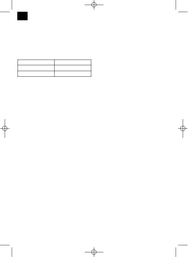
Anleitung BG_BC_41_43_SPK1:_ 07.03.2008 10:17 Uhr Seite 30
F
et homologués à cet effet.
Remplacez respectivement de la bonne quantité dʼessence et dʼhuile deux temps dans la bouteille de mélange ci-jointe (voir lʼéchelle imprimée). Secouez ensuite bien la bouteille.
6.3 Tableau de mélange du carburant :
Mélanger : 25 parts dʼessence pour une part dʼhuile
Essence |
Huile deux temps |
1 litre |
40 ml |
5 litres |
200 ml |
7. Fonctionnement
Veuillez respecter les directives légales relatives à lʼordonnance de la protection contre le bruit. Elles peuvent différer dʼun endroit à lʼautre.
7.1 Faire démarrer le moteur froid
Remplissez le réservoir de la quantité correcte de mélange essence/huile. Voir chapitre Combustible et huile.
1.Placez lʼappareil sur une surface solide et plane.
2.Mettez le levier étrangleur (fig. A/pos. 10) aur „  “.
“.
3.Appuyez 10 x sur la pompe à carburant (Primer) (fig. A/pos. 16).
4.Connectez lʼinterupteur Marche / Arrêt (fig. A/pos. 6) sur “I”
5.Bloquez le levier de lʼaccélérateur. Pour y arriver, actionnez le blocage de lʼaccélérateur (fig. A/pos. 7), puis lʼaccélérateur (fig. A/pos. 8) et appuyez simultanément sur le bouton de blocage
(fig. A/pos. 9), ce qui fixe lʼaccélérateur.
6.Tenez bien lʼappareil et tirez le cordon de démarrage (fig. A/pos. 11) jusquʼà la première résistance. Tirez ensuite dʼun coup 4 fois le cordon de démarrage. Lʼappareil doit démarrer. Attention : Ne laissez pas le cordon de démarrage rentrer trop rapidement. Ceci peut entraîner des dommages.
7.Lorsque le moteur a démarré, mettez immédiatement le levier étrangleur sur “  ” et laissez lʼappareil atteindre sa température de service pendant environ. 10 sec.
Attention : Comme lʼaccélérateur est fixé dans sa position, lʼoutil de découpage se met en route dès que le moteur démarre.
Actionnez ensuite lʼaccélérateur pour le déverrouiller (le moteur se remet en marche à vide).
8.Si le moteur ne démarre pas, recommencez les
30
étapes 6-7.
Observations : Si le moteur ne démarre toujours pas au bout de plusieurs essais, veuillez lire le paragraphe “Élimination des erreurs“.
Observations : Tirez toujours la corde de démarrage toute droite. Si vous la tirez en lui faisant faire un angle, une friction aura lieu au niveau de lʼoeillet. Ce frottement écorche la corde qui sʼuse plus vite. Maintenez toujours la poignée de démarrage lorsque la corde retourne à sa place.
Ne laissez jamais la corde retourner rapidement de son état tiré. Ceci endomamgerait également le fil ou entraîner des dommages du starter.
7.2 Faire démarrer le moteur chaud
(lʼappareil nʼest pas resté plus de 15-20 mn à lʼarrêt)
1.Placez lʼappareil sur une surface solide et plane.
2.Mettez lʼinterrupteur Marche/arrêt sur „I“.
3.Bloquez lʼaccélérateur (comme pour „Lancer le moteur froid“).
4.Tenez bien lʼappareil et tirez le cordon de démarrage jusquʼà la première résistance. Maintenant, tirez fortement sur le cordon de démarrage. Lʼappareil doit démarrer au bout de 1 à 2 essais. Si la machine ne démarre toujours pas au bout de 6 essais, recommencez les étape
1 à 7 “Lancer le moteur froid”.
7.3 Mettre le moteur hors circuit
Suite des étapes pour un arrêt dʼurgence :
Sʼil est nécessaire de mettre la machine immédiatement hors circuit, mettez lʼinterrupteur Marche/arrêt sur “Stop” ou “0”.
Suite dʼétapes normale :
Relâchez lʼaccélérateur et attendez jusquʼà ce que le moteur passe en vitesse de marche à vide. Mettez ensuite lʼinterupteur Marche / Arrêt sur „Stop“ ou encore „0“.
7.4 Consignes de travail
Avant dʼutiliser lʼappareil, entraînez-vous à faire toutes les techniques de travail avec le moteur à lʼarrêt.
PROLONGATION DU FIL DE COUPE AVERTISSEMENT : Nʼutilisez aucun fil métallique ni même de fil métallique enrobé de plastique de quelque sorte que ce soit dans la tête de fil. Ceci peut entraîner des blessures graves de lʼutilisateur. Pour prolonger le fil de coupe, laissez le moteur tourner à pleine vitesse et tapotez (“BUMP”) la tête de fil au sol. Le fil sʼallonge automatiquement. La lame sur lʼécran de protection racourcit le fil à la longueur admise (fig. I1).
 Loading...