


DOUBLE CD PLAYER
DN-2600F
OPERATING INSTRUCTIONS
BEDIENUNGSANLEITUNG
MODE D’EMPLOI
INSTRUCCIONES DE OPERACION
GEBRUIKSAANWIJZING
BRUKSANVISNING
|
OPEN / |
|
|
|
|
|
|
|
|
|
|
|
|
OPEN / |
|
|
|
|
|
|
|
|
|
|
|
|
2600F-DN |
|
DN-2600F |
CLOSE |
|
|
|
|
|
|
|
|
|
|
|
|
CLOSE |
|
|
|
|
|
|
|
|
|
|
|
|
||
|
|
|
1 |
CONT. |
PROG. |
|
ELAPSED |
|
PITCH % |
MEMO |
BRAKE |
PITCH |
KEY. |
|
|
1 |
CONT. |
PROG. |
|
ELAPSED |
|
PITCH % |
MEMO |
BRAKE |
PITCH |
KEY. |
||
|
|
|
|
m |
s |
f |
|
|
|
|
|
|
|
|
m |
s |
f |
|
|
|
|
|
||||||
CONT. /SINGLE |
TIME |
BRAKE |
|
|
|
|
|
|
CONT. /SINGLE TIME |
BRAKE |
|
|
|
|
|
|
||||||||||||
|
|
DN-2600F |
SAMP |
LOOP |
|
|
|
|
|
|
DN-2600F |
SAMP |
LOOP |
|
|
|
|
|||||||||||
|
|
|
|
LOOP |
A1 B |
|
|
|
|
|
|
|
LOOP |
A1 B |
|
|
|
|
||||||||||
|
|
|
|
|
|
|
|
|
|
|
|
|
|
|
|
|
|
|
|
|
||||||||
|
|
|
|
|
|
|
|
|
|
|
- |
|
+ |
|
|
|
|
|
|
|
|
|
|
- |
|
+ |
||
|
|
|
|
|
|
|
|
|
|
PROGRAM |
PITCH BEND |
|
|
|
|
|
|
|
|
|
PROGRAM |
PITCH BEND |
||||||
NEXT TR. START |
END MON. |
|
LOOP |
A |
B |
|
|
|
|
|
NEXT TR. START |
END MON. |
|
LOOP |
A |
B |
|
|
|
|
|
|||||||
SEARCH |
|
|
1 |
2 |
|
|
PUSH ENTER |
|
|
|
SEARCH |
|
|
1 |
2 |
|
|
PUSH ENTER |
|
|
|
|||||||
|
|
|
|
SEARCH |
SCAN |
|
|
|
|
|
|
|
|
SEARCH |
SCAN |
|
|
|
|
|
||||||||
EFFECT |
|
|
|
|
|
|
FIL |
RVB |
FLG |
|
|
|
|
EFFECT |
|
|
|
|
|
FIL |
RVB |
FLG |
|
|
|
|
||
|
|
|
|
|
|
|
|
|
|
|
|
|
|
|
|
|
|
|
|
|
|
|
|
|
||||
|
|
|
|
|
|
|
REVERSE |
LOOP |
PITCH |
|
|
|
|
|
|
|
|
|
|
REVERSE |
LOOP |
PITCH |
|
|
|
|
||
|
|
E N |
D |
|
|
|
TAP |
|
ON/OFF |
|
|
|
|
|
E N |
D |
|
|
|
TAP |
|
ON/OFF |
|
|
|
|
||
|
B |
|
|
|
|
|
DATA MASTER |
|
|
0% |
B |
|
|
|
|
|
DATA MASTER |
|
|
0% |
||||||||
|
|
|
|
|
|
|
|
|
|
|
|
|
|
|
|
|
|
|
|
|
||||||||
Y |
|
|
|
|
|
|
|
|
|
|
|
|
Y |
|
|
|
|
|
|
|
|
|
|
|
||||
|
|
|
|
|
|
STOP |
PLAY/WRITE |
|
|
|
|
|
|
|
|
|
STOP |
PLAY/WRITE |
|
|
|
|
||||||
E |
|
|
|
|
|
|
|
|
|
|
E |
|
|
|
|
|
|
|
|
|
||||||||
K |
|
|
|
|
|
|
|
|
|
|
|
|
|
K |
|
|
|
|
|
|
|
|
|
|
|
|
||
S |
|
|
|
|
|
|
|
|
|
|
|
|
|
S |
|
|
|
|
|
|
|
|
|
|
|
|
||
- |
|
|
|
|
|
|
|
|
|
MODE |
|
|
|
- |
|
|
|
|
|
|
|
|
MODE |
|
|
|
||
I |
|
|
|
|
|
|
|
|
|
|
|
|
I |
|
|
|
|
|
|
|
|
|
|
|
||||
G |
|
|
|
|
|
|
CUE |
PLAY/PAUSE |
|
|
|
G |
|
|
|
|
|
CUE |
PLAY/PAUSE |
|
|
|
||||||
I |
|
|
|
|
|
|
|
|
|
|
I |
|
|
|
|
|
|
|
|
|
||||||||
D |
|
|
|
|
|
|
|
|
|
|
|
|
|
D |
|
|
|
|
|
|
|
|
|
|
|
|
||
|
|
|
|
|
|
|
|
|
|
|
|
|
|
|
|
|
|
|
|
|
|
|
|
|
|
|
||
|
|
|
|
|
|
|
|
|
|
|
PRESET |
|
|
|
|
|
|
|
|
|
|
|
|
PRESET |
|
|
|
|
REMOTE CONTROL UNIT RC-46
DN-2600F
FOR ENGLISH READERS
FÜR DEUTSCHE LESER
POUR LES LECTEURS FRANCAIS PARA LECTORES DE ESPAÑOL VOOR NEDERLANDSTALIGE LEZERS FÖR SVENSKA LÄSARE
PAGE |
007 |
~ PAGE |
027 |
SEITE |
028 |
~ SEITE |
048 |
PAGE |
049 |
~ PAGE |
069 |
PAGINA 070 |
~ PAGINA |
090 |
|
PAGINA 091 |
~ PAGINA |
111 |
|
SIDA |
112 |
~ PAGINA |
132 |
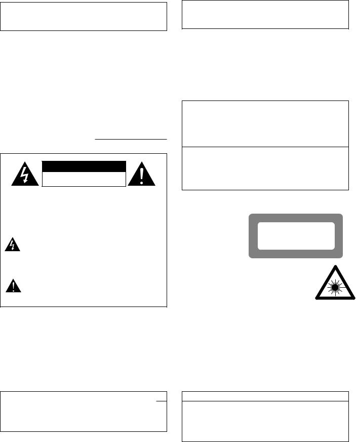
IMPORTANT TO SAFETY
WARNING:
TO PREVENT FIRE OR SHOCK HAZARD, DO NOT EXPOSE THIS APPLIANCE TO RAIN OR MOISTURE.
CAUTION:
1.Handle the power supply cord carefully
Do not damage or deform the power supply cord. If it is damaged or deformed, it may cause electric shock or malfunction when used. When removing from wall outlet, be sure to remove by holding the plug attachment and not by pulling the cord.
2.Do not open the top cover
In order to prevent electric shock, do not open the top cover. If problems occur, contact your DENON dealer.
3.Do not place anything inside
Do not place metal objects or spill liquid inside the CD player. Electric shock or malfunction may result.
Please, record and retain the Model name and serial number of your set shown
on the rating label. |
|
Model No. DN-2600F |
Serial No. |
CAUTION
RISK OF ELECTRIC SHOCK
DO NOT OPEN
CAUTION: TO REDUCE THE RISK OF ELECTRIC SHOCK, DO NOT REMOVE COVER (OR BACK). NO USERSERVICEABLE PARTS INSIDE. REFER SERVICING TO QUALIFIED SERVICE PERSONNEL.
The lightning flash with arrowhead symbol, within an equilateral triangle, is intended to alert the user to the presence of uninsulated “dangerous voltage” within the product’s enclosure that may be of sufficient magnitude to constitute a risk of electric shock to persons.
The exclamation point within an equilateral triangle is intended to alert the user to the presence of important operating and maintenance (servicing) instructions in the literature accompanying the appliance.
NOTE:
This CD player uses the semiconductor laser. To allow you to enjoy music at a stable operation, it is recommended to use this in a room of 5 °C (41 °F) –35 °C (95 °F).
LABELS (for U.S.A. model only)
CERTIFICATION
THIS PRODUCT COMPLIES WITH DHHS RULES 21 CFR SUBCHAPTER J APPLICABLE AT DATE OF MANUFACTURE.
CAUTION:
USE OF CONTROLS OR ADJUSTMENTS OR PERFORMANCE OF PROCEDURES OTHER THAN THOSE SPECIFIED HEREIN MAY RESULT IN HAZARDOUS RADIATION EXPOSURE.
THE COMPACT DISC PLAYER SHOULD NOT BE ADJUSTED OR REPAIRED BY ANYONE EXCEPT PROPERLY QUALIFIED SERVICE PERSONNEL.
This device complies with Part 15 of the FCC Rules. Operation is subject to the following two conditions : (1) This device may not cause harmful interference, and (2) this device must accept any interference received, including interference that may cause undesired operation.
This Class B digital apparatus meets all requirements of the Canadian Interference-Causing Equipment Regulations.
Cet appareil numérique de la classe B respecte toutes les exigences du Règlement sur le matériel brouilleur du Canada.
CLASS 1 LASER PRODUCT LUOKAN 1 LASERLAITE
KLASS 1 LASERAPPARAT
,,CLASS 1
LASER PRODUCT,,
ADVARSEL: |
USYNLIG LASERSTRÅLING VED ÅBNING, NÅR |
|
SIKKERHEDSAFBRYDERE ER UDE AF FUNKTION. |
|
UNDGÅ UDSAETTELSE FOR STRÅLING. |
VAROITUS! |
LAITTEEN KÄYTTÄMINEN MUULLA KUIN TÄSSÄ |
|
KÄYTTÖOHJEESSA MAINITULLA TAVALLA SAATTAA |
|
ALTISTAA KÄYTTÄJÄN TURVALLISUUSLUOKAN 1 |
|
YLITTÄVÄLLE NÄKYMÄMTTÖMÄLLE LASERSÄTEILYLLE. |
VARNING– |
OM APPARATEN ANVÄNDS PÅ ANNAT SÄTT ÄN I DENNA |
|
BRUKSANVISNING SPECIFICERATS, KAN ANVÄNDAREN |
|
UTSÄTTAS FÖR OSYNLIG LASERSTRÅLNING SOM |
|
ÖVERSKRIDER GRÄNSEN FÖR LASERKLASS 1. |
• FOR U.S.A. & CANADA MODEL ONLY
CAUTION
TO PREVENT ELECTRIC SHOCK DO NOT USE THIS (POLARIZED) PLUG WITH AN EXTENSION CORD, RECEPTACLE OR OTHER OUTLET UNLESS THE BLADES CAN BE FULLY INSERTED TO PREVENT BLADE EXPOSURE.
•POUR LES MODELES AMERICAINS ET CANADIENS UNIQUEMENT
ATTENTION
POUR PREVENIR LES CHOCS ELECTRIQUES NE PAS UTILISER CETTE FICHE POLARISEE AVEC UN PROLONGATEUR UNE PRISE DE COURANT OU UNE AUTRE SORTIE DE COURANT, SAUF SI LES LAMES PEUVENT ETRE INSEREES A FOND SANS EN LAISSER AUCUNE PARTIE A DECOUVERT.
2
SAFETY INSTRUCTIONS
1.Read Instructions – All the safety and operating instructions should be read before the appliance is operated.
2.Retain Instructions – The safety and operating instructions should be retained for future reference.
3.Heed Warning – All warnings on the appliance and in the operating instructions should be adhered to.
4.Following Instructions – All operating and use instructions should be followed.
5.Water and Moisture – The appliance should not be used near water – for example, near a bathtub, washbbowl, kitchen sink, laundry tub, in a wet basement, or near a swimming pool, and the like.
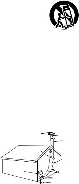
6.Carts and Stands – The appliance should be used only with a cart or stand that is recommended by the manufacturer.
6A. An appliance and cart combination should be moved with care. Quick stops, excessive force, and uneven surfaces may cause the appliance and cart
combination to overturn.
7.Wall or Ceiling Mounting – The appliance should be mounted to a wall or ceiling only as recommended by the manufacturer.
8.Ventilation – The appliance should be situated so that its location or position does not interfere with its proper ventilation. For example, the appliance should not be situated on a bed, sofa, rug, or similar surface that may block the ventilation openings; or, placed in a built-in installation, such as a bookcase or cabinet that may impede the flow of air through the ventilation openings.
9.Heat – The appliance should be situated away from heat sources such as radiators, heat registers, stoves, or other appliances (including amplifiers) that produce heat.
10.Power Sources – The appliance should be connected to a power supply only of the type described in the operating instructions or as marked on the appliance.
11.Grounding or Polarization – Precautions should be taken so that the grounding or polarization means of an appliance is not defeated.
FIGURE A
EXAMPLE OF ANTENNA GROUNDING
AS PER NATIONAL
ELECTRICAL CODE ANTENNA
LEAD IN
WIRE
GROUND
CLAMP
ANTENNA DISCHARGE UNIT
(NEC SECTION 810-20)
ELECTRIC
SERVICE
EQUIPMENT
GROUNDING CONDUCTORS (NEC SECTION 810-21)
GROUND CLAMPS
POWER SERVICE GROUNDING ELECTRODE SYSTEM
(NEC ART 250, PART H)
NEC - NATIONAL ELECTRICAL CODE
12.Power-Cord Protection – Power-supply cords should be routed so that they are not likely to be walked on or pinched by items placed upon or against them, paying particular attention to cords at plugs, convenience receptacles, and the point where they exit from the appliance.
14.Cleaning – The appliance should be cleaned only as recommended by the manufacturer.
15.Power Lines – An outdoor antenna should be located away from power lines.
16.Outdoor Antenna Grounding – If an outside antenna is connected to the receiver, be sure the antenna system is grounded so as to provide some protection against voltage surges and built-up static charges. Article 810 of the National Electrical Code, ANSI/NFPA 70, provides information with regard to proper grounding of the mast and supporting structure, grounding of the lead-in wire to an antenna-discharge unit, size of grounding conductors, location of antenna-discharge unit, connection to grounding electrodes, and requirements for the grounding electrode. See Figure A.
17.Nonuse Periods – The power cord of the appliance should be unplugged from the outlet when left unused for a long period of time.
18.Object and Liquid Entry – Care should be taken so that objects do not fall and liquids are not spilled into the enclosure through openings.
19.Damage Requiring Service – The appliance should be serviced by qualified service personnel when:
A.The power-supply cord or the plug has been damaged; or
B.Objects have fallen, or liquid has been spilled into the appliance; or
C.The appliance has been exposed to rain; or
D.The appliance does not appear to operate normally or exhibits a marked change in performance; or
E.The appliance has been dropped, or the enclosure damaged.
20.Servicing – The user should not attempt to service the appliance beyond that described in the operating instructions. All other servicing should be referred to qualified service personnel.
3
SVENSKA |
NEDERLANDS ESPAÑOL FRANCAIS DEUTSCH ENGLISH |
NOTE ON USE / HINWEISE ZUM GEBRAUCH / OBSERVATIONS RELATIVES A L’UTILISATION NOTAS SOBRE EL USO / ALVORENS TE GEBRUIKEN / OBSERVERA
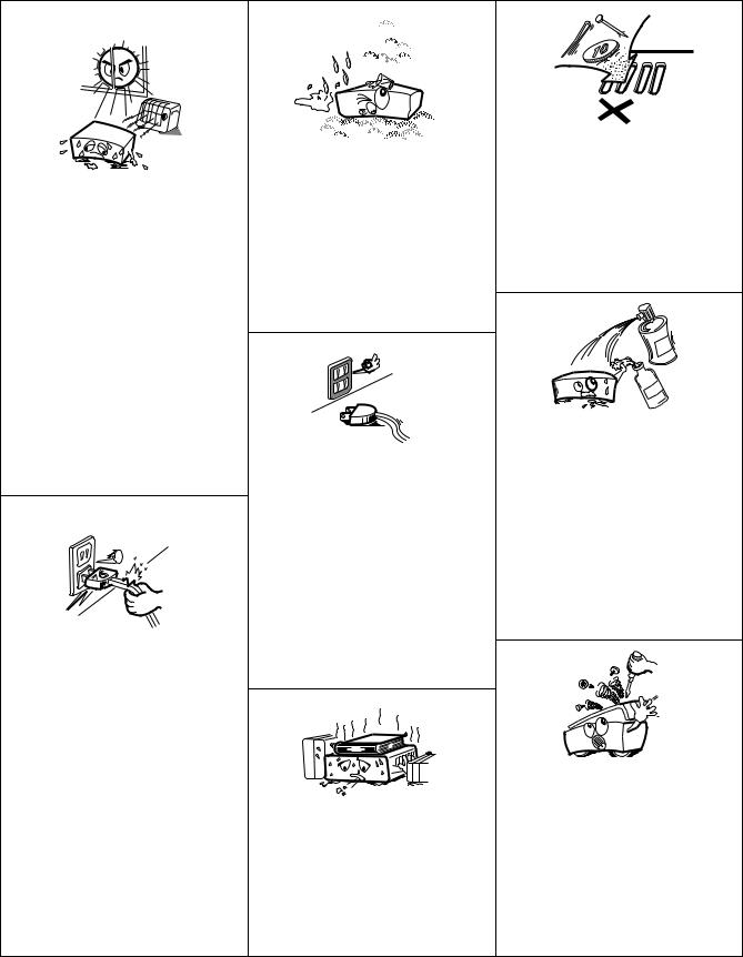
•Avoid high temperatures.
Allow for sufficient heat dispersion when installed on a rack.
•Vermeiden Sie hohe Temperaturen. Beachten Sie, daß eine ausreichend Luftzirkulation gewährleistet wird, wenn das Gerät auf ein Regal gestellt wird.
•Eviter des températures élevées.
Tenir compte d’une dispersion de chaleur suffisante lors de l’installation sur une étagère.
•Evite altas temperaturas.
Permite la suficiente dispersión del calor cuando está instalado en la consola.
•Vermijd hoge temperaturen.
Zorg voor een degelijk hitteafvoer indien het apparaat op een rek wordt geplaatst.
•Undvik höga temperaturer.
Se till att det finns möjlighet till god värmeavledning vid montering i ett rack.
•Handle the power cord carefully.
Hold the plug when unplugging the cord.
•Gehen Sie vorsichtig mit dem Netzkabel um.
Halten Sie das Kabel am Stecker, wenn Sie den Stecker herausziehen.
•Manipuler le cordon d’alimentation avec précaution.
Tenir la prise lors du débranchement du cordon.
•Maneje el cordón de energía con cuidado. Sostenga el enchufe cuando desconecte el cordón de energía.
•Hanteer het netsnoer voorzichtig.
Houd het snoer bij de stekker vast wanneer deze moet worden aanof losgekoppeld.
•Hantera nätkabeln varsamt.
Håll i kabeln när den kopplas från el-uttaget.
•Keep the set free from moisture, water, and dust.
•Halten Sie das Gerät von Feuchtigkeit, Wasser und Staub fern.
•Protéger l’appareil contre l’humidité, l’eau et lapoussière.
•Mantenga el equipo libre de humedad, agua y polvo.
•Laat geen vochtigheid, water of stof in het apparaat binnendringen.
•Utsätt inte apparaten för fukt, vatten och damm.
•Unplug the power cord when not using the set for long periods of time.
•Wenn das Gerät eine längere Zeit nicht verwendet werden soll, trennen Sie das Netzkabel vom Netzstecker.
•Débrancher le cordon d’alimentation lorsque l’appareil n’est pas utilisé pendant de longues périodes.
•Desconecte el cordón de energía cuando no utilice el equipo por mucho tiempo.
•Neem altijd het netsnoer uit het stopkontakt wanneer het apparaat gedurende een lange periode niet wordt gebruikt.
•Koppla ur nätkabeln om apparaten inte kommer att användas i lång tid.
*(For sets with ventilation holes)
•Do not obstruct the ventilation holes.
•Die Belüftungsöffnungen dürfen nicht verdeckt werden.
•Ne pas obstruer les trous d’aération.
•No obstruya los orificios de ventilación.
•De ventilatieopeningen mogen niet worden beblokkeerd.
•Täpp inte till ventilationsöppningarna.
•Do not let foreign objects in the set.
•Keine fremden Gegenstände in das Gerät kommen lassen.
•Ne pas laisser des objets étrangers dans l’appareil.
•No deje objetos extraños dentro del equipo.
•Laat geen vreemde voorwerpen in dit apparaat vallen.
•Se till att främmande föremål inte tränger in i apparaten.
•Do not let insecticides, benzene, and thinner come in contact with the set.
•Lassen Sie das Gerät nicht mit Insektiziden, Benzin oder Verdünnungsmitteln in Berührung kommen.
•Ne pas mettre en contact des insecticides, du benzène et un diluant avec l’appareil.
•No permita el contacto de insecticidas, gasolina y diluyentes con el equipo.
•Laat geen insektenverdelgende middelen, benzine of verfverdunner met dit apparaat in kontakt komen.
•Se till att inte insektsmedel på spraybruk, bensen och thinner kommer i kontakt med apparatens hölje.
•Never disassemble or modify the set in any way.
•Versuchen Sie niemals das Gerät auseinander zu nehmen oder auf jegliche Art zu verändern.
•Ne jamais démonter ou modifier l’appareil d’une manière ou d’une autre.
•Nunca desarme o modifique el equipo de ninguna manera.
•Nooit dit apparaat demonteren of op andere wijze modifiëren.
•Ta inte isär apparaten och försök inte bygga om den.
4
ENGLISH DEUTSCH FRANCAIS ESPAÑOL NEDERLANDS SVENSKA
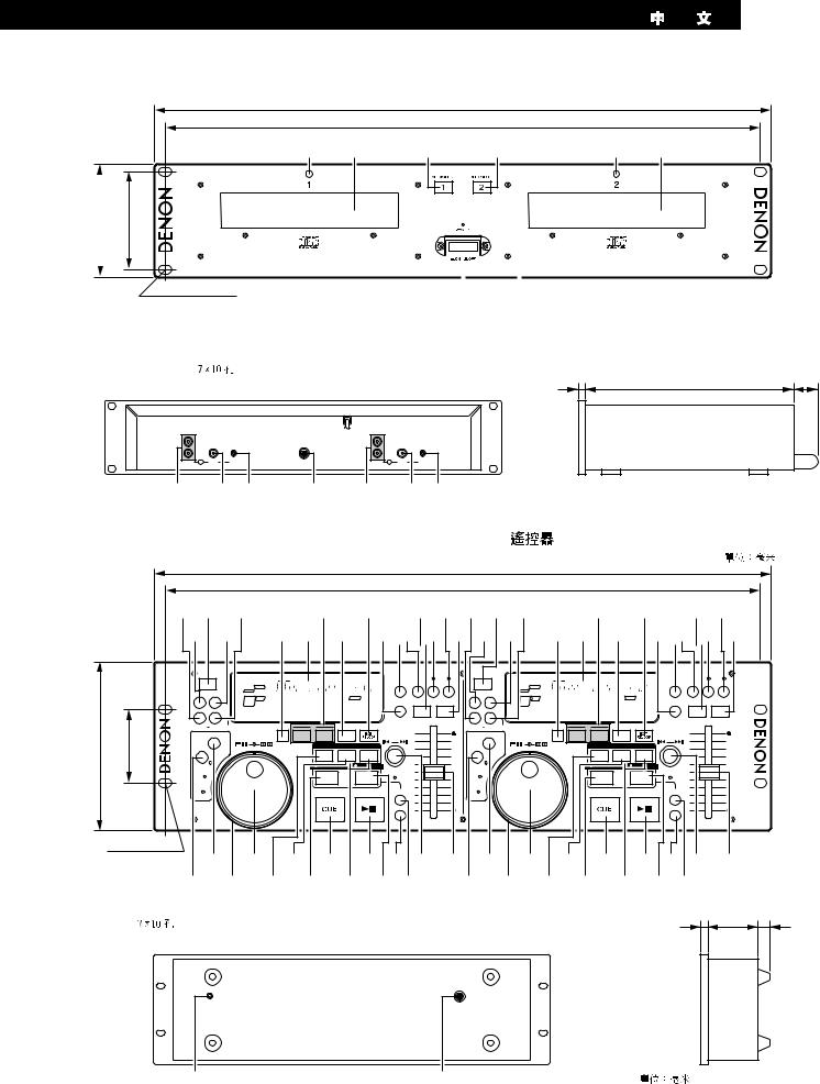
Main Unit / Hauptgerät / Unité principale / Unidad principal / Hoofdtoestel / Huvudenhet / 

88 |
76.2 |
|
|
482
465
r e t t |
r e |
DN-2600F |
|
7 x 10 hole |
|
|
|
|
|
|
|
|
|
q |
w |
|||
|
|
|
|
|
Loch 7 x 10 |
|
|
|
|
Trou de 7 x 10 |
|
|
|
|
Orificio de 7 x 10 |
|
|
|
|
Opening 7 x 10 |
|
|
|
|
Hål, 7 x 10 |
|
|
|
|
|
|
|
|
|
|
|
|
2 |
250 |
50 |
|
|
|
|
|
|
|
|
|
||
|
L |
|
|
|
|
L |
|
|
|
|
|
R |
|
|
|
|
R |
|
|
|
|
ANALOG |
2 |
DIGITAL |
FADER |
REMOTE |
ANALOG |
1 |
DIGITAL |
FADER |
|
|
OUT |
OUT |
OUT |
OUT |
|
|
|||||
y |
|
u i |
o |
y |
|
u i |
|
Gerät: mm |
||
|
|
|
|
|
|
|
|
|
|
Unit: mm |
Remote Control Unit / Fernbedienungsgerät / Unité de télécommande / |
|
Unité: mm |
||||||||
|
Unidad: mm |
|||||||||
Unidad de control remoto / Afstandsbediening / Fjärrkontroll / |
|
Toestel: mm |
||||||||
|
Enhet: mm |
|||||||||
|
|
|
|
|
|
|
|
|
|
|
482
465
$1#9#7 |
#4 #2#0@8@6$1#9#7 |
#4 #2#0@8@6 |
||||||||
$0#8 |
#6#5 #3 |
#1@9@7@5$0#8 |
#6#5 #3 |
#1@9@7@5 |
||||||
|
|
|
|
|
|
|
|
|
|
|
|
|
|
OPEN / |
|
|
|
|
|
|
|
|
|
|
|
OPEN / |
|
|
|
|
|
|
|
|
|
|
|
2600F-DN |
|
|
132 |
57.2 |
2600F-DN |
CLOSE |
|
|
|
|
|
|
|
|
|
|
|
CLOSE |
|
|
|
|
|
|
|
|
|
|
|
|
||
|
|
|
1 |
CONT. |
PROG. |
|
ELAPSED |
|
PITCH % |
MEMO |
BRAKE PITCH |
KEY. |
|
|
1 |
CONT. |
PROG. |
|
ELAPSED |
|
PITCH % |
MEMO |
BRAKE PITCH |
KEY. |
|
||||
|
|
|
|
|
|
|
m |
s |
f |
|
|
|
|
|
|
|
m |
s |
f |
|
|
|
|
|
|
||||
|
|
|
CONT. /SINGLE |
TIME |
BRAKE |
|
|
|
|
|
CONT. /SINGLE TIME |
BRAKE |
|
|
|
|
|
|
|
||||||||||
|
|
|
|
|
DN-2600F |
SAMP |
LOOP |
|
|
|
|
|
DN-2600F |
SAMP |
LOOP |
|
|
|
|
|
|||||||||
|
|
|
|
|
|
|
LOOP |
A1 B |
|
|
|
|
|
|
LOOP |
A1 B |
|
|
|
|
|
||||||||
|
|
|
|
|
|
|
|
|
|
|
|
|
|
|
|
|
|
|
|
|
|
|
|
||||||
|
|
|
|
|
|
|
|
|
|
|
|
|
|
- |
+ |
|
|
|
|
|
|
|
|
|
|
- |
+ |
|
|
|
|
|
|
|
|
|
|
|
|
|
|
|
PROGRAM |
PITCH BEND |
|
|
|
|
|
|
|
|
|
PROGRAM |
PITCH BEND |
|
|
||
|
|
|
NEXT TR. START |
END MON. |
|
LOOP |
A |
B |
|
|
|
|
NEXT TR. START |
END MON. |
|
LOOP |
A |
B |
|
|
|
|
|
|
|||||
|
|
|
SEARCH |
|
|
1 |
2 |
|
|
PUSH ENTER |
|
|
SEARCH |
|
|
1 |
2 |
|
|
PUSH ENTER |
|
|
|
|
|||||
|
|
|
|
|
|
|
SEARCH |
SCAN |
|
|
|
|
|
|
|
|
|
SEARCH |
SCAN |
|
|
|
|
|
|
|
|
||
|
|
|
EFFECT |
|
|
|
|
|
|
FIL |
RVB |
FLG |
|
|
|
EFFECT |
|
|
|
|
|
FIL |
RVB |
FLG |
|
|
|
|
|
|
|
|
|
|
|
|
|
|
|
|
|
|
|
|
|
|
|
|
|
|
|
|
|
|
|
|
|
||
|
|
|
|
|
|
|
|
|
|
REVERSE |
LOOP |
PITCH |
|
|
|
|
|
|
|
|
|
REVERSE |
LOOP |
PITCH |
|
|
|
|
|
|
|
|
|
|
E N |
D |
|
|
|
TAP |
|
ON/OFF |
|
|
|
|
E N |
D |
|
|
|
TAP |
|
ON/OFF |
|
|
|
|
|
|
|
|
|
B |
|
|
|
|
|
DATA MASTER |
|
0% |
B |
|
|
|
|
|
DATA MASTER |
|
0% |
|
|
||||||
|
|
|
|
|
|
|
|
|
|
|
|
|
|
|
|
|
|
|
|
|
|
|
|
||||||
|
|
|
Y |
|
|
|
|
|
|
|
|
|
|
|
Y |
|
|
|
|
|
|
|
|
|
|
|
|
||
|
|
|
|
|
|
|
|
|
STOP |
PLAY/WRITE |
|
|
|
|
|
|
|
|
STOP |
PLAY/WRITE |
|
|
|
|
|
||||
|
|
|
E |
|
|
|
|
|
|
|
|
|
E |
|
|
|
|
|
|
|
|
|
|
||||||
|
|
|
K |
|
|
|
|
|
|
|
|
|
|
|
|
K |
|
|
|
|
|
|
|
|
|
|
|
|
|
|
|
|
S |
|
|
|
|
|
|
|
|
|
|
|
|
S |
|
|
|
|
|
|
|
|
|
|
|
|
|
|
|
|
- |
|
|
|
|
|
|
|
|
|
MODE |
|
|
- |
|
|
|
|
|
|
|
|
MODE |
|
|
|
|
|
|
|
G |
|
|
|
|
|
|
|
|
|
|
|
G |
|
|
|
|
|
|
|
|
|
|
|
|
||
|
|
|
I |
|
|
|
|
|
|
CUE |
PLAY/PAUSE |
|
|
|
I |
|
|
|
|
|
CUE |
PLAY/PAUSE |
|
|
|
|
|
||
|
|
|
I |
|
|
|
|
|
|
|
|
|
I |
|
|
|
|
|
|
|
|
|
|
||||||
|
|
|
D |
|
|
|
|
|
|
|
|
|
|
|
|
D |
|
|
|
|
|
|
|
|
|
|
|
|
|
|
|
|
|
|
|
|
|
|
|
|
|
|
PRESET |
REMOTE CONTROL UNIT RC-46 |
|
|
|
|
|
|
|
PRESET |
|
|
|
|
|||
|
|
|
|
|
|
|
|
|
|
|
|
|
|
|
|
|
|
|
|
|
|
|
|
|
|
||||
|
7 x 10 hole |
|
!1 !3 !5 !7 !9@1@3@4 !1 !3 !5 !7 !9@1@3@4 |
|
|||||||||||||||||||||||||
|
Loch 7 x 10 |
|
|
||||||||||||||||||||||||||
|
|
|
|
|
|
|
|
|
|
|
|
|
|
|
|
|
|
|
|
|
|
|
|
|
|
|
|
|
|
|
Trou de 7 x 10 |
!0 !2 !4 !6 !8 @0@2 |
|
!0 !2 !4 !6 !8 @0@2 |
|
|
|
||||||||||||||||||||||
|
Orificio de 7 x 10 |
|
|
|
|
||||||||||||||||||||||||
|
Opening 7 x 10 |
|
|
|
|
|
|
|
|
|
|
|
|
|
|
|
|
|
|
|
|
|
|
|
|
|
|
|
|
|
Hål, 7 x 10 |
|
|
|
|
|
|
|
|
|
|
|
|
|
|
|
|
|
|
|
|
|
|
|
|
2 |
38 |
|
18 |
|
|
|
|
|
|
|
|
|
|
|
|
|
|
|
|
|
|
|
|
|
|
|
|
|
|
|
|||
|
|
|
|
|
|
|
|
|
|
|
|
|
|
|
|
|
|
|
|
|
|
|
|
|
|
|
|
|
|
|
Unit: mm |
|
Gerät: mm |
|
Unité: mm |
|
Unidad: mm |
|
Toestel: mm |
|
Enhet: mm |
$2 |
$3 |
5
ENGLISH DEUTSCH FRANCAIS ESPAÑOL NEDERLANDS SVENSKA
•DECLARATION OF CONFORMITY
We declare under our sole responsibility that this product, to which this declaration relates, is in conformity with the following standards: EN60065, EN55013, EN55020, EN61000-3-2 and EN61000-3-3.
Following the provisions of 73/23/EEC, 89/336/EEC and 93/68/EEC Directive.
•ÜBEREINSTIMMUNGSERKLÄRUNG
Wir erklären unter unserer Verantwortung, daß dieses Produkt, auf das sich diese Erklärung bezieht, den folgenden Standards entspricht:
EN60065, EN55013, EN55020, EN61000-3-2 und EN61000-3-3. Entspricht den Verordnungen der Direktive 73/23/EEC, 89/336/EEC und 93/68/EEC.
•DECLARATION DE CONFORMITE
Nous déclarons sous notre seule responsabilité que l’appareil, auquel se réfère cette déclaration, est conforme aux standards suivants: EN60065, EN55013, EN55020, EN61000-3-2 et EN61000-3-3. D’après les dispositions de la Directive 73/23/EEC, 89/336/EEC et 93/68/EEC.
•DECLARACIÓN DE CONFORMIDAD
Declaramos bajo nuestra exclusiva responsabilidad que este producto al que hace referencia esta declaración, está conforme con los siguientes estándares:
EN60065, EN55013, EN55020, EN61000-3-2 y EN61000-3-3. Siguiendo las provisiones de las Directivas 73/23/EEC, 89/336/EEC y 93/68/EEC.
•EENVORMIGHEIDSVERKLARING
Wij verklaren uitsluitend op onze verantwoordelijkheid dat dit produkt, waarop deze verklaring betrekking heeft, in overeenstemming is met de volgende normen:
EN60065, EN55013, EN55020, EN61000-3-2 en EN61000-3-3. Volgens de bepalingen van de Richtlijnen 73/23/EEC, 89/336/EEC en 93/68/EEC.
•ÖVERENSSTÄMMELSESINTYG
Härmed intygas helt på eget ansvar att denna produkt, vilken detta intyg avser, uppfyller följande standarder:
EN60065, EN55013, EN55020, EN61000-3-2 och EN61000-3-3. Enligt stadgarna i direktiv 73/23/EEC, 89/336/EEC och 93/68/EEC.
COMPACT
DIGITAL AUDIO
• Använd CD-skivor med  -märket.
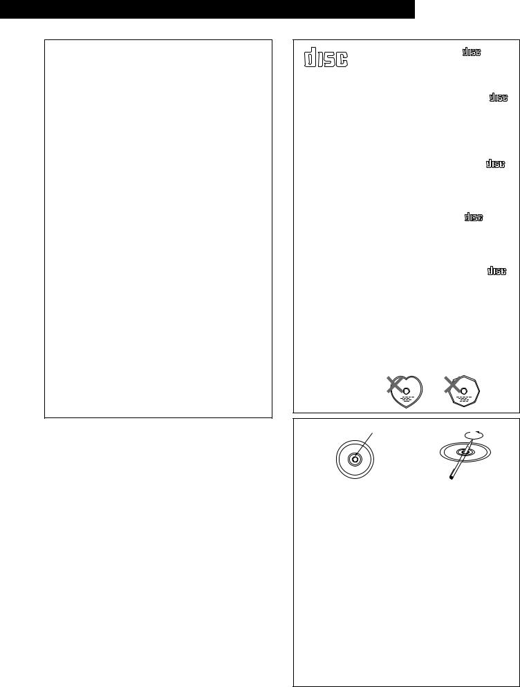
Disc
•The disc may not play normally if there is residue along the edges of the center hole.
•When using new discs in particular, use a pen, etc., to remove the residue.
•Die Disk kann nicht normal abgespielt werden, wenn sich ein Rückstand entlang der Mittellochenden befindet.
•Insbesondere, wenn Sie neue Disks benutzen, dann entfernen Sie mit einem Stift, etc. den Rückstand.
•Le disque peut ne pas être lu normalements s’il y a un résidu le long des bord du trou central.
•Lors de l’utilisation de nouveaux disques en particulier, utiliser un stylo à bille, etc., pour enlever le résidu.
•El disco no puede ser reproducido normalmente debido a la terminación deficiente de los bordes del agujero central.
•Para quitar estos residuos de material, especialmente cuando vaya a reproducir discos nuevos, utilice un bolígrafo, o algo similar.
•Het is mogelijk dat de disc niet normaal wordt weergegeven als de randen van het middengat van de schijf oneffenheden vertonen.
•Verwijder vooral bij gebruik van nieuwe discs de oneffenheden met een pen of iets dergelijks.
•Det kan uppstå fel vid CD-avspelningen om det finns plastrester kvar i mitthålet.
•Tänk på att bort dessa med en penna, e d, särskilt om CD-skivan är ny.
6

ENGLISH
— TABLE OF CONTENTS —
z Main features …………………………………………………………7
x Connections/Installation ……………………………………………7
c Part names and functions ……………………………………8 ~ 11 v Compact discs ………………………………………………………11
b Basic operation ……………………………………………………12
n Pitch/Brake/Platter/Key control ……………………………………13
m Next track reserve …………………………………………………14
, Seamless loop/Hot start/Stutter ……………………………15, 16
. Sampler/Digital scratch/Effector ……………………………17 ~ 20
⁄0Memo ………………………………………………………………21
⁄1Programmed playback …………………………………………22, 23
⁄2Random playback …………………………………………………24
⁄3Preset functions and operations ……………………………25, 26
⁄4Cleaning the optical pick-up lens …………………………………27
⁄5Specifications ………………………………………………………27
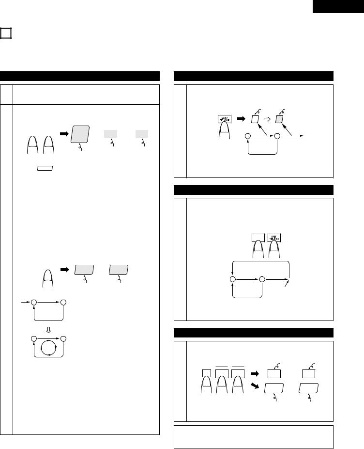
• ACCESSORIES
Check that the following parts are included in addition to the main unit:
q Operating instructions ……………………………………………1 |
e Remote control unit (RC-46) ………………………………………1 |
w Connection cords for signal output (RCA) ………………………2 |
r Remote control connection cable ………………………………1 |
|
|
1 MAIN FEATURES
The DN-2600F is a double CD player equipped with a variety of functions and rich performance characteristics. Use it for example for DJ mixing and remixing.
Control section
1.The DN-2600F can be easily mounted on a standard 19-inch rack.
2.Improved visibility thanks to a large fluorescent display, selflighting buttons and disc holder illumination.
3.Improved operability thanks to a large jog/shuttle dial and track select knob.
Functions
1.Shockproof function protecting against external vibrations
2.Auto Level Search / Instant Start
3.Pitch Bend (Button & Jog)
4.Seamless Loop
Playback can be looped between any two positions with no break in the sound. Two loop start points (A-1 and A-2) can be set.
5.Hot Start / Stutter
Playback can be started instantaneously from points A-1 and A-2. In the stutter mode, the disc is only played while the button is pressed.
6.Sampler
The sound of the CD can be sampled and played for approximately 15 seconds. The loop, reverse, pitch adjustment, playback level adjustment and key adjustment functions can be used with the sampled sound.
7.Digital-Scratch
This function allows scratching in a way similar to analog discs.
2CONNECTIONS/INSTALLATION
1.Turn off the POWER switch.
2.Connect the RCA pin cords to the inputs on your mixer.
3.Connect the control cord to the REMOTE connector on the RC-46.
CAUTION:
•Be sure to use the supplied control cord. Using another type of cable may result in damage.
•Be sure the power is off when connecting the control cord. Otherwise the units may not work properly.
•Never connect any remote controllers other than the RC-46. Doing so can damage the equipment.
18. Effector (Filter, Reverb, Flanger)
Three different effector functions can be used to create a variety of effect sounds.
19. Brake / Platter
The playing speed can be gradually lowered to play and stop discs with a sound similar to that of analog discs.
10.Next Track Reserve
The next track to be played can be selected so that playback continues with no break in the sound.
11.Memo
Up to 300 sets of such data as the cue point, loop A/B points and pitch can be stored in a permanent memory (one set of data per track).
12.Key Control / Key Adjust
Key control function for adjusting the playback key. In addition, the key can be adjusted automatically when the playing pitch changes so that the key remains the same.
13.End Monitor
The ends of tracks can be monitored.
14.Program / Random playback
Up to 25 tracks can be programmed, and programs for up to six discs can be stored in a permanent memory. Random playback is performed for the discs in both disc holders.
15.Fader input
16.Servo Auto Stop function for Spindle Motor / Disc Holder Auto Close
17.Preset function for setting functions according to the usage purpose
15°
The DN-2600F will work normally when the player unit is mounted within 15 degrees off the vertical plane at the front panel. If the unit is tilted excessively, the disc may not be loaded or unloaded properly.
DN-2600F
7

ENGLISH
3PART NAMES AND FUNCTIONS
(1)DN-2600F Front Panel
q POWER button (¢ON £OFF)
• Press this button to turn the power on.
NOTE:
•Be sure to close the disc holders before turning off the power.
w POWER indicator
• This lights when the power is on.
e Disc holder
•Place discs in this holder.
•Press the disc holder OPEN/CLOSE button to open and close the disc holder.
CAUTION:
•Do not place foreign objects in the disc holders. Doing so could damage the player.
•Do not push the disc tray in manually when the power is off, as this may result in malfunction and damage the player.
r Disc holder LED
•This flashes while the disc holder is opening and closing.
•The LED lights when the disc holder is open and serves as the disc holder illumination.
t Disc holder OPEN/CLOSE button
•Press this button to open and close the disc holder.
•The disc holder will not open during playback. Stop playback before pressing this button.
(2)DN-2600F Rear Panel
y Analog output jacks 1, 2 (ANALOG OUT 1, 2)
•These are unbalanced output jacks. The audio signals from the CD players are output from these jacks.
u Digital output jacks 1, 2 (DIGITAL OUT 1, 2)
•Digital data is output from these jacks according to the presettings.
•We recommend using a 75Ω/ohm pin cord (available in stores) for connections.
NOTES:
•Turn PITCH control OFF when making digital recordings. Most digital recorders will not accept a variable pitched digital signal.
•The functions are limited when outputting digital data. (The loop, brake, Plat, Bend-Jog, scratch, sampler, effector and key control functions cannot be used.)
iFader input jacks 1, 2 (FADER 1, 2)
•Use this when using the unit with a console fader. (Mini Jack)
(FADER INPUT LEVEL HCMOS (Ii=–3mA))
•The fader can be activated using the switch circuit shown on the diagram below.
|
|
|
SW 1 |
Lch |
|
|
|
|
|||
|
|
|
|
|
|
SW 2
GND
 GND*
GND*
•Connect SW1 to the “Lch” stereo mini jack.
•Connect SW2 to the “GND” stereo mini jack.
•Connect GND* to the analog output “GND” terminal.
•Do not use the “Rch” jack.
•When SW1 is pressed, the hot start play mode selected with the A1 and A2 buttons starts.
•When SW2 is pressed, the hot start play mode stops.
Load the hot start data before starting fader playback.
o Remote control connector (REMOTE)
•Connect this connector to the RC-46 control unit using the included control cord.
(3)RC-46 Front Panel
!0EFFECT button
•Press this button is pressed to select the jog dial operating mode.
Pitch bend mode:
When the jog dial is turned, the playing speed changes at a fixed rate. (The BEND LED lights.)
Plat-H mode:
When the jog dial is turned, the playing speed changes in function of the speed at which the jog dial is turned.
(The BEND LED and the “ PLAT-H ” indicator light.)
Key mode:
The key can be adjusted by turning the jog dial. (The KEY LED lights.)
Scratch mode:
Scratching is possible by turning the jog dial. (The DIGI-S LED lights.)
!1SEARCH button
•When this button is pressed while the jog dial operating mode is set to pitch bend, plat-H, key or scratch, the jog and shuttle dial operating mode is set to the search mode.
!2Shuttle dial (outer side)
•The shuttle dial can be used in the search mode.
•Use this dial to select the scanning direction and speed.
•The disc is scanned in the forward direction when the shuttle dial is turned clockwise from the neutral position, and in the reverse direction when the shuttle dial is turned counterclockwise.
•The scanning speed increases as the wheel is turned further.
8

!3Jog dial (inner side)
•In the search mode, turn this dial during the search operation to move the playing point in units of frames.
•In the pitch bend and plat-H modes, turn this to change the playing speed.
•In the key mode, turn this to adjust the key.
•In the scratch mode, turn this to scratch.
!4Filter/Reverse button (FIL/REVERSE)
•In the sampler mode, press this button to turn the sampler reverse play mode on and off.
•In the effector mode, press this button to set the filter parameter input mode.
!5Reverb/Loop button (RVB/LOOP)
•In the sampler mode, press this button to turn the sampler loop play mode on and off.
•In the effector mode, press this button to set the reverb parameter input mode.
!6TAP (TAP/BPM)/STOP button
•In the sampler mode, press this button to stop sample recording/playback.
•In the sampler mode, press this button for over 2 seconds to delete the sample data.
•In cases other than the above, the tempo at which the button is pressed is measured and this is input as the BPM. When the button is pressed only once, the BPM is displayed.
!7CUE button
•Pressing the CUE button during play provides a return to the position at which play was started. Alternately pressing the PLAY/PAUSE button and the CUE button allows the CD to be played from the same position any number of times.
•The button lit, when the standby mode is set.
•When in the sleep mode, cancel the sleep mode.
!8Flanger/Pitch button (FLG/PITCH)
•In the sampler mode, press this button to set the sampler parameter input mode.
•In the effector mode, press this button to set the flanger parameter input mode.
!9PLAY/PAUSE button (13)
•Use this button to start playback.
•Press once to start playback, once again to set the pause mode, and once more to resume playback.
•In the brake mode, press this button to brake.
@0ON/OFF, PLAY/WRITE button
•In the sampler mode, press this button to start sample recording/playback.
•Press this button to turn the various effectors on and off.
@1PRESET button
•Press this button once to turn the preset input mode on. Press it again to turn the preset input mode off.
@2MODE button
•When this button is pressed, the ASP operation selection mode is set.
ENGLISH
@3Track select/Data master knob (8–9/PUSH ENTER)
•Turn this knob to select the next track to be played.
•Turn the knob clockwise by one click to move one track forward, counterclockwise by one click to move one track backward.
•When the knob turned while pressing it in, one click corresponds to 10 tracks.
•In the preset mode, use this knob to set and enter preset settings.
•When setting programs, use this knob to select, enter and check the program.
•In the memo mode, use the knob to set the item, to enter the setting, to check the setting and to delete the setting.
•This knob is used to select the ASP operation mode and to set data in various modes.
@4Pitch slider
•Use this to adjust the playing speed.
•The playing speed decreases when slid upwards and increases when slid downwards.
@5PITCH BEND + button
•The playing speed increases while this button is pressed.
•When the button is released, the playing speed returns to the previous speed.
@6Key control button (KEY)
•When this button is pressed, the key control mode is set and the key can be adjusted with the jog dial.
•When pressed again, the key adjust mode is turned on and the key remains the same even if the pitch is changed. (KEY ADJUST)
@7PITCH button
•Press this button to switch to the play speed set with the Pitch slider. The PITCH LED lights.
•When the button is pressed again, the fixed pitch mode is set and the PITCH LED flashes.
•Press the button again to cancel the pitch play mode and return to normal speed.
@8PITCH BEND – button
•The playing speed decreases while this button is pressed.
•When the button is released, the playing speed returns to the previous speed.
@9BRAKE button
•Press this button to select the brake mode (BRAKE/PLAT-S mode).
#0MEMO button
•Press this button to set the memo mode.
•The following data is stored in the memory:
Standby position, A-1 point, A-2 point, B point, playing pitch.
#1PROGRAM button
• Press this button to set the program mode.
9
ENGLISH
#2EXIT/RELOOP button
•When this button is pressed during loop playback, loop playback stops and the normal play mode is set (EXIT). When pressed again, loop playback resumes.
#3B (B-LOOP) button
•Press this button to set the end point for loop playback (point B).
#8TIME button
•Press this to switch the time display between the elapsed time or remaining time per track or per disc.
#9Disc holder OPEN/CLOSE button
•Press this button to open and close the disc holder.
•The disc holder will not open during playback. Stop playback before pressing this button.
#4A button (1, 2)
•Press this button to set the start point for loop playback (point A-1 or A-2).
•Press this button to use the stutter and hot start functions. The hot start mode is set when the loop mode is on, the stutter mode is set when the loop mode is off.
$0Continue/Single button (CONT./SINGLE)
•Press this button to switch between the single and continuous play modes.
•The selected mode is indicated by the SINGLE or CONTINUE indicators on the display.
#5Display
• See page 10.
#6LOOP (FLIP) button
•Press this button to switch between the loop mode/hot start mode and stutter mode.
•The “ LOOP ” indicator lights when in the loop mode/hot start mode.
•When in the next track mode, program mode or random mode, press this button to turn the repeat mode on and off.
#7End monitor / Next track start button (END MON. / START)
•Press this button in the standby mode to monitor the end of the track.
•When this button is pressed during playback in the next track mode, the selected track is search for. When pressed again after the search operation, playback starts.
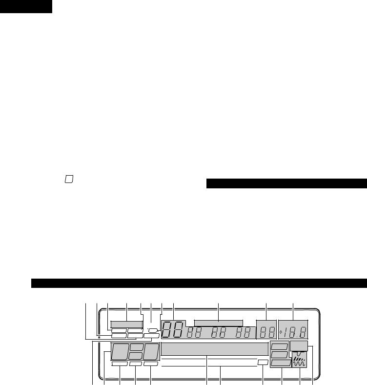
(5)Display
$1Next track button (NEXT TR.)
•Press this button to set the next track mode.
•When the next track mode is set, the “NEXT TR” indicator lights and the next track to be played can be selected using the track select knob.
(4)RC-46 Rear Panel
$2Connector for signal transfer between remote control units
•When this connector is connected to the connector of another RC-46 using a stereo mini-plug cord (cross cable), signals can be transferred between two units.
$3Control connector
•Connect this connector to the REMOTE connector on the DN-2600F (main unit) using the included control cord.
q w e r ty u i |
o |
!0 !1 |
|
CONT. SINGLE REPEAT |
TOTAL REMAIN ELAPSED |
NEXT TR PITCH % |
|
MEMO PROG. |
GO! |
m s |
f |
BRAKE PLAT-S |
PLAT-H |
||
LOOP |
A1 B |
EXIT |
|
A2 B |
|||
|
|
||
D.OUT |
FULL |
LOCK |
¡¡¡¡¡¡¡¡¡¡¡ SAMPDIGI-S RVSLOOP


 EOM EFFECT
!2!3 !4 !5 !6 |
!7!8 |
!9 @0 @1@2 |
q PLAT-S indicator
• This lights when in the PLAT-S mode.
w Brake indicator
• This lights when in the brake mode.
e Memo indicator
• This lights when memo data is stored in the memory.
r Play mode indicators
•“SINGLE” lights when in the single track play mode.
•“CONT.” lights when in the continuous play mode.
t Program indicator
•This lights when program data has been input and when program data is stored in the memory.
y Repeat indicator
• This lights when the repeat mode is set. u Digital scratch enabled indicator
•This lights when it is possible to start digital scratching.
iTrack, minute, second and frame displays
•These displays indicate information on the current position and time.
10
o Time mode indicators
•When the TIME button is pressed, the time display switches as follows:
When “ELAPSED” is lit:
The track’s elapsed time is displayed. When “REMAIN” is lit:
The track’s remaining time is displayed. When “TOTAL” and “ELAPSED” are lit: The disc’s total elapsed time is displayed. When “TOTAL” and “REMAIN” are lit: The disc’s total remaining time is displayed.
!0Next track display
• This displays the number of the next tack to be played.
!1Pitch display
•This indicates the playback speed (pitch). (–16.0 to +16.0)
!2PLAT-H indicator
• This lights when in the PLAT-H mode.
!3Loop mode indicators
•“ LOOP ” lights when in the loop mode.
•“ A1 B ” lights when point B is set for point A-1.
•“ A2 B ” lights when point B is set for point A-2.
•“ EXIT ” lights when in the seamless loop pause mode.
!4Digital out indicator
•This lights when the digital output is turned on with the presettings.
!5Shockproof data indicator
• This lights when the shockproof memory is full.
!6Button lock indicator
• Some of the buttons do not function when this indicator is lit.
!7Character display
• Operation messages are displayed here.
!8Bar indicator
•This provides a visual indication of where the pickup is within the currently playing track.
!9EOM indicator
•This flashes when the EOM time set with the presettings is reached.
@0ASP mode indicators
•“ SAMP ” lights when the ASP is set to the sampler playing mode.
•“ DIGI-S ” lights when the ASP is set to the digital scratch mode.
•“ EFFECT ” lights when the ASP is set to the effector mode.
@1Effector operating mode indicators
•“  ” lights when in the filter mode.
•“ 
 ” lights when in the reverb mode.
•“  ” lights when in the flanger mode.
@2Sampler playing mode indicators
•“LOOP” lights when in the sampler loop playing mode.
•“RVS” lights when in the sampler reverse playing mode.
ENGLISH
4COMPACT DISCS
1.Precautions on handling compact discs
•Do not allow fingerprints, oil or dust to get on the surface of the disc.
If the disc is dirty, wipe it off with a soft dry cloth.
•Do not use benzene, thinner, water, record spray, electrostaticproof chemicals, or silicone-treated cloths to clean discs.
•Always handle discs carefully to prevent damaging the surface; in particular when removing a disc from its case or returning it.
•Do not bend the disc.
•Do not apply heat.
•Do not enlarge the hole in the center of the disc.
•Do not write on the label (printed side) with a hard-tipped implement such as a pencil or ball point pen.
•Condensation will form if a disc is brought into a warm area from a colder one, such as outdoors in winter. Do not attempt to dry the disc with a hair dryer, etc.
2.Precautions on storage
•After playing a disc, always unload it from the player.
•Always store the disc in the jewel case to protect from dirt or damage.
•Do not place discs in the following areas:
1)Areas exposed to direct sunlight for a considerable time.
2)Areas subject to accumulation of dust or high humidity.
3)Areas affected by heat from indoor heaters, etc.
11
ENGLISH
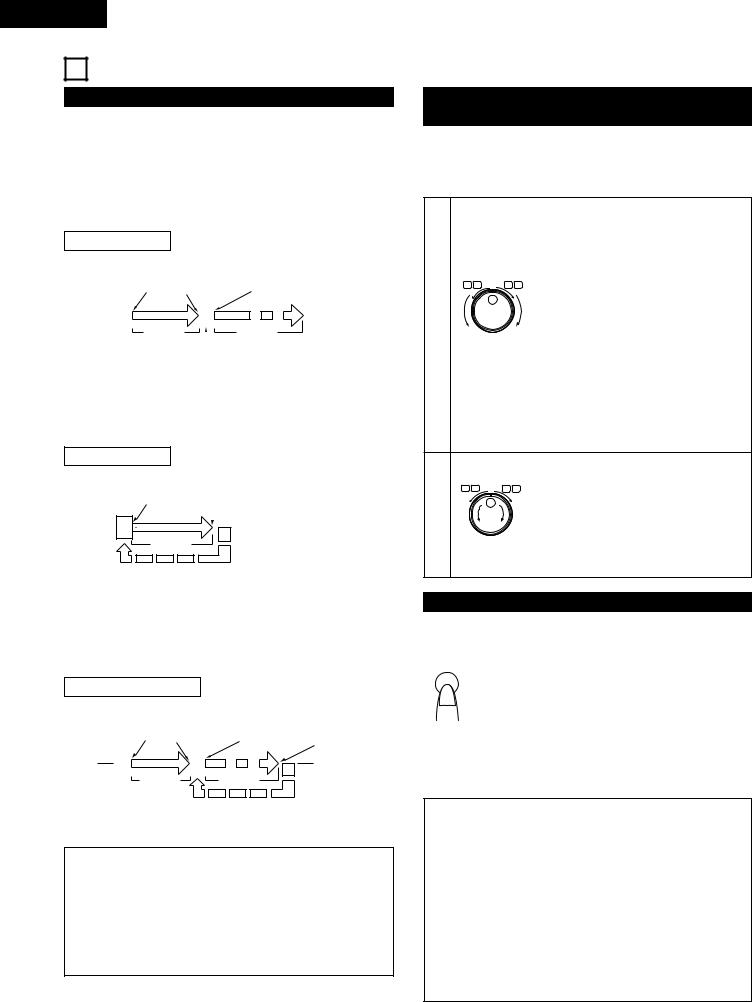
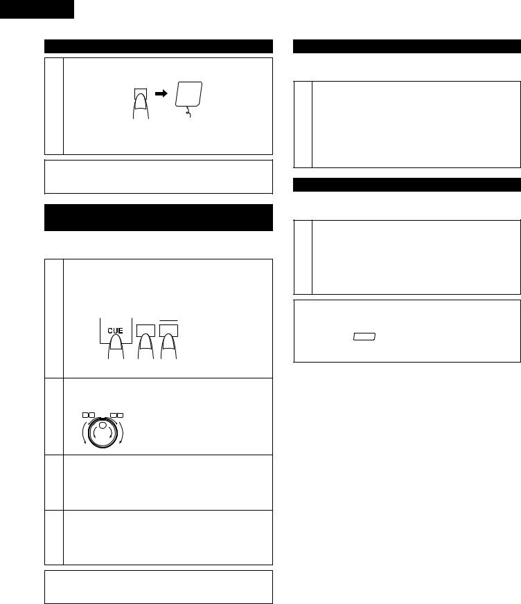
5 BASIC OPERATION
PLAY/PAUSE and CUE
The operation switches between playback and pause each time the PLAY/PAUSE button is pressed.
When the CUE button is pressed during playback, the pickup returns to the position at which playback was started.
The diagrams below show playback patterns when the PLAY/PAUSE and CUE buttons are pressed.
PLAY and PAUSE
PLAY/PAUSE |
PLAY/PAUSE |
|||||||||
button |
button |
|
|
|
|
|||||
pressed |
pressed |
|
PLAY/PAUSE button pressed |
|||||||
|
|
|
|
|
|
|
|
|
|
Position on disc |
|
|
|
|
|
|
|
|
|
|
|
|
|
|
|
|
|
|
|
|
||
|
|
|
Section |
|
|
|
Section |
|||
|
|
|
|
|
||||||
|
|
|
played |
|
|
|
|
played |
||
|
|
|
|
|
|
|
|
Pause mode set at this point |
||
|
|
|
|
|
|
|
|
|||
When the PLAY/PAUSE button is pressed, playback starts and proceeds as shown by the arrow on the diagram above.
If the PLAY/PAUSE button is pressed again during playback, the pause mode is set at that point. Press the PLAY/PAUSE button again to resume playback.
PLAY and CUE
PLAY/PAUSE |
|
|
button |
CUE button pressed |
|
pressed |
|
|
|
|
|
|
|
|
Position on disc
Section
played
Back Cue
When the CUE button is pressed after starting playback by pressing the PLAY/PAUSE button, the pickup returns to the position at which playback was started and prepares for the next playback.
Press the PLAY/PAUSE and CUE buttons alternately to start playback repeatedly from the same position. (Checking the playback position) This function is called “Back Cue”.
PLAY, PAUSE and CUE
PLAY/PAUSE |
PLAY/PAUSE |
PLAY/PAUSE |
|
||||
button |
button |
|
|
||||
|
button |
CUE |
|||||
pressed |
pressed |
|
|||||
|
pressed |
||||||
|
button pressed |
||||||
|
|
|
|
|
|
||
|
|
|
|
|
|
|
|
|
|
|
|
|
Section |
Position on disc |
|
|
|
Section |
|
|
|||
|
|
|
|
||||
|
|
played |
|
|
played |
|
|
If the pause mode is set and playback is then resumed, the position to which the pickup returns with the Back Cue function changes.
Sleep mode
•The sleep mode is set if no operation is performed for 30 minutes while in the standby or pause mode. In the sleep mode, disc rotation is stopped in order to reduce wear due to unnecessary rotation of the motor.
•The sleep mode can be canceled by pressing the PLAY/PAUSE or CUE button. (The time after which the sleep mode is set can be selected with the presettings.)
Starting playback from the Middle of a track (Manual Search)
When the track is selected with the track select knob and the PLAY/PAUSE button is pressed, playback starts from the beginning of that track. If you wish to start from a different position, use the procedure described below to search for the desired position.
Find the play start position.
Press the SEARCH button to set the jog/shuttle dial to the search mode.
Turn the shuttle dial to change the playback position quickly. (Search for the approximate playback position.)
SEARCH |
§ |
SCAN |
The fast forward/reverse mode is set when |
||
I II |
6 |
7 |
|||
|
|
||||
|
|
|
|
the shuttle dial (outer side) is turned. |
|
1 |
|
|
|
The speed changes according to the angle |
|
|
|
|
at which the dial is turned. |
||
RVS |
FWD |
|
|||
•When operated during playback, playback resumes after the operation.
•When playback is started, the jog dial is set to the bend mode.
•When turned fully in either direction, the disc skips 1 minute forward or backward then plays for 3 seconds, and this is repeated.
Turn the jog dial. (Search for the precise playback position.)
SEARCH |
SCAN |
When the jog dial (inner side) is turned, the |
I |
§6 7 |
|
I I |
|
|
2 |
|
frame move mode is set. |
|
The playback position can be moved in |
|
|
|
units of one frame. |
RVS |
FWD |
|
Listen to the sound and find the desired play start position.
Checking the position at which playback will stop
In the standby mode, press the END MON. button.
•The end monitored, then the pickup returns to the play
start position and the standby mode is set. (End
END MON.
Monitor)
•In the single track play mode, the end of the current track is monitored.
•In the continuous play mode, the end of the final track is monitored.
•If the CUE button is pressed during the end monitor operation, the end monitor operation is canceled, the pickup returns to the play start position and the standby mode is set.standby mode is set.
Shockproof memory
•A maximum of approximately 10 seconds worth of audio data is stored in the memory during playback, thereby reducing skipping and interruptions in the sound due to track skipping and other problems generated by vibrations.
•If advanced data reading is not possible due to scratches or dirt on the disc, playback stops once the data stored up to that point is read.
•If less than 3 seconds worth of data remains in the memory, “Read Error” flashes on the character display, indicating that playback will stop.
•The display returns to normal once the amount of data in the
memory increases.
12
ENGLISH
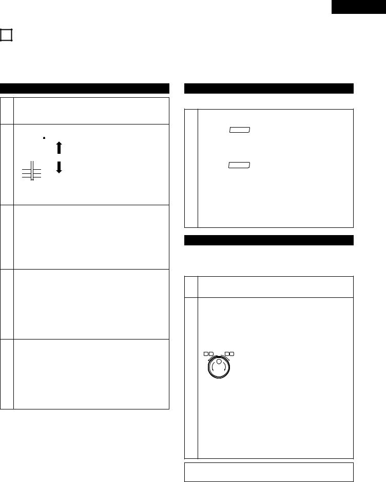
6PITCH/BRAKE/PLATTER/KEY CONTROL
There are two ways to change the playing speed.
•Adjust the Pitch using the pitch slider (±10% and ±16%).
•The PITCH BEND button or jog dial can be used to temporarily change the pitch.
The playing speed can be changed greatly to achieve effects similar to those achievable with analog discs.
Pitch/Platter-H
[Pitch slider]
1-1 Set the variable speed mode.
Press the PITCH button to light the PITCH LED.
|
|
|
|
|
|
|
Pitch |
|
|
|
|
|
|
|
decreases |
|
|
|
|
|
|
|
|
|
|
|
|
|
|
|
|
|
|
|
|
|
|
|
The Pitch decreases when the pitch |
|
|
|
|
|
|
|
|
|
|
|
|
|
|
|
|
|
|
|
|
|
|
0% |
slider is moved upwards, increases |
1-2 |
|
|
|
|
|
|
when the pitch slider is moved |
|
|
|
|
|
|
||
|
|
|
|
|
|
downwards. |
|
|
|
|
|
|
|
 Pitch
Pitch
increases
•The pitch can be locked by pressing the PITCH button again.
|
[PITCH BEND button] |
|
Press the PITCH BEND + (or PITCH BEND –) button. |
|
• The Pitch increases or decreases temporarily while the |
2-1 |
PITCH BEND + or PITCH BEND – button is pressed. |
• The extent to which the PITCH BEND button changes the |
|
|
Pitch is proportionate to the amount of time the button is |
|
pressed. The longer the button is held down, the greater |
|
the percentage of change. |
Set the jog dial to the pitch bend mode.
Press the EFFECT button to light the BEND LED.
•The playing speed increases gradually when the jog dial is turned clockwise and decreases gradually when the jog
2-2 dial is turned counterclockwise. When you stop turning the jog dial, the playing speed returns to the previous speed.
•When playback is stopped, the jog/shuttle dial is set to the search mode.
Set the jog dial to the platter hold mode.
Press the EFFECT button to light the BEND LED.
•The playing speed changes in function of the speed at which the jog dial is turned, resulting in a sound similar to
3that of when using an analog disc.
•The playing speed increases when the jog dial is turned clockwise and decreases when the jog dial is turned counterclockwise. When you stop turning the jog dial, the playing speed returns to the previous speed.
Brake/Platter-S
Use this function to achieve two effects similar to analog players.
|
Select the brake or platter mode. |
|
|
Press the BRAKE button. |
|
|
• When “ BRAKE ” is lit: Brake mode |
|
|
An effect sound similar to that of when playback is |
|
|
stopped on an analog player can be achieved by pressing |
|
|
the PLAY/PAUSE button during playback. |
|
|
• The brake time can be selected with the presettings. |
|
1 |
• When “ PLAT-S ” is lit: Platter start/stop mode |
|
The platter stop effect is achieved when the PLAY/PAUSE |
||
|
||
|
button is pressed during playback and the platter start |
|
|
effect is achieved when the PLAY/PAUSE button is |
|
|
pressed in the standby or pause mode. The platter stop |
|
|
and start effects are effect sounds similar to when |
|
|
playback is started or stopped on an analog player. |
•The start and stop times time can be selected with the presettings.
Key control
This function allows you to adjust the key of the playback sound.
A key adjust function adjusts the key automatically when the playing pitch changes so that the key remains the same.
1Set the key control mode.
Press the KEY button to light the KEY LED.
|
[Adjusting the key] |
||||||
2-1 Set the jog dial to the key mode. |
|||||||
|
Press the EFFECT button to light the KEY LED. |
||||||
|
|
|
|||||
|
Adjust the key. |
|
|||||
|
Turn the jog dial. |
|
|||||
|
SEARCH |
§ |
SCAN |
|
|||
|
I |
I |
6 |
7 |
|
||
|
|
I |
|
|
The key increases when the jog dial is |
||
|
|
|
|
|
|
||
2-2 |
|
|
|
|
|
turned clockwise and decreases when the |
|
|
|
|
|
|
jog dial is turned counterclockwise. |
||
|
|
|
|
|
|
||
|
• |
The key is indicated on the bar indicator. The original key |
|||||
|
|
is at the center, and one bar corresponds to two steps. |
|||||
|
• |
The key adjustment range is ±16.0. |
|||||
|
|
||||||
|
[Key adjust mode] |
||||||
|
Compensate for the change in the key when the playing |
||||||
3 |
speed is changed with the pitch slider. |
||||||
Press the KEY button to make the KEY LED flash. |
|||||||
|
|||||||
|
• |
The key is kept at the same key as when the pitch is 0%. |
|||||
|
The key cannot be adjusted with the jog dial. |
||||||
NOTE:
• When the disc holder is opened, the key data is cleared.
13

ENGLISH
7NEXT TRACK RESERVE
With this function, the blank sections between tracks when in the continuous play mode can be cut (AUTO MODE). It is also possible to freely search for and select the next track to be played while the current track is playing so that playback continues with no break in the sound (MANUAL MODE).
Set the next track mode.
Press the NEXT TR. button.
NEXT TR
1 |
Lit |
The NEXT TR. button may not function if there are less than 20 seconds remaining in the currently playing track.
The next track mode cannot be selected when the A and B points are set in the loop mode.
Select the track to be played next.
During playback, turn the track select knob.
[Example: To play track 3 next]
|
PUSH ENTER |
2 |
NEXT TR |
If no next track is selected, the current track is selected when in the single track play mode and the following track is selected when in the continuous play mode.
[Next track manual mode]
Switch playback to the selected track.
If you wish to switch to the selected track while the current track is still playing, press the START button.
Next Tr. OK
3
•When “Next Tr. OK” is displayed, press the START button again to stop the currently playing track and start playing the next track.
•If the START button is not pressed again when “Next Tr. OK” is displayed, playback of the currently playing track stops after a maximum of approximately 10 seconds, then playback of the selected track starts. The remaining time of the current track is indicated on the time display.
[Next track auto mode]
When the next track is selected and the START button is not pressed, playback of the next track starts automatically once the currently playing track is finished, with no break in the
4sound.
•In the single track play mode, the standby mode is set at the beginning of the next track.
•You can choose whether to turn the repeat function on or off using the LOOP button.
[Canceling the next track reserve mode]
Press the NEXT TR. button again.
5
NEXT TR
NOTE:
•The “ LOCK ” indicator lights from the time the standby mode is set at the next track until playback starts.
During this time, it is not possible to set the pause mode, to use the manual search, scan or next track functions or to switch between the single track and continuous play modes.
Off
14
ENGLISH
8SEAMLESS LOOP/HOT START/STUTTER
Use this function to play the specified section between points A and B in a seamless loop (with no break in the sound).
Two A points and one B point can be set.
The data of the A points can be used for the hot start and stutter functions.
Starting seamless loop playback
1Start playback.
Press the PLAY/PAUSE button.
Load the start point (A).
|
Press the A-1 (or A-2) button. |
|
|
|
|
|
|||||||
|
|
|
A |
|
|
|
|
|
|
|
|
||
|
|
|
|
|
|
|
|
|
|
||||
|
|
|
|
|
|
|
|
|
|
|
|
|
|
|
|
1 |
|
2 |
|
LOOP |
|
1 |
or |
2 |
|
||
|
|
|
|
|
|
|
Lit |
|
Lit |
|
Lit |
||
|
|
|
|
|
|
|
|
|
|
|
|
||
|
• The seamless loop mode is set as soon as point A is set. |
||||||||||||
2 |
• The “ |
LOCK ” indicator lights and “LoadA” is displayed |
|||||||||||
on the character display while the A point data is being |
|||||||||||||
|
|||||||||||||
|
loaded. |
|
|
|
|
|
|
||||||
|
The seamless loop mode cannot be set when in the next |
||||||||||||
|
track mode. If you wish to set it, turn the next track |
||||||||||||
|
mode off. |
|
|
|
|
|
|
||||||
|
Data cannot be loaded for both A1 and A2 at the same |
||||||||||||
|
time. |
|
|
|
|
|
|
|
|
|
|
||
|
Depending on the conditions, it may not be possible to |
||||||||||||
|
load points A1 and A2. In this case, “Not Load” is |
||||||||||||
|
displayed. |
|
|
|
|
|
|
||||||
|
|
|
|
|
|
|
|
|
|
|
|
|
|
|
Set the end point (B). |
|
|
|
|
|
|
||||||
|
Press the B (B-LOOP) button. |
|
|
|
|
|
|||||||
|
|
|
|
|
B |
|
|
|
|
|
|
||
|
|
|
|
|
|
|
A1 B |
or A2 B |
|
|
|||
|
|
|
|
|
|
|
|
|
|||||
|
|
|
|
|
|
|
Lit |
|
|
Lit |
|
|
|
Start point |
End point |
When the end point (B) is set, the disc is played from the start point
(A) with no break.
Start point |
End point |
3
After this, the disc is played from
the start point (A) to the end point
(B) with no break.
Seamless loop
•If the B (B-LOOP) button is pressed again after the B point has been set, the B point is reset (moves).
•Whenever the A-1 (or A-2) button is pressed while in the seamless loop mode, playback starts over from the A point.
•When point B is set for point A-1 and the A-2 button is pressed, point B is cleared. In the same way, when point B is set for point A-2 and the A-1 button is pressed, point B is cleared.
Temporarily canceling seamless looping
Press the EXIT/RELOOP button during seamless looping. (EXIT mode)
|
|
Flashing |
Lit |
|
EXIT |
EXIT |
|
4 |
Start point |
End point |
|
|
|
|
•When the end point (B) is reached, playback continues, without returning to the start point (A).
Replaying a seamless loop
Press the EXIT/RELOOP button or the B (B-LOOP) button during normal playback. (When the B (B-LOOP) button is pressed, that point is set as the new loop end point (B).)
B
5
End point
Start point
Press the EXIT/RELOOP or B button.
•Playback returns to the start point (A) and seamless looping resumes.
Clearing the start (A) and end (B) points
While pressing the LOOP (FLIP) button, press the A button you want to clear (A-1 or A-2) for at least 2 seconds.
|
Off |
Off |
LOOP |
A |
|
1 |
2 |
1 |
or |
2 |
6 |
|
A1 B |
|
A2 B |
|
|
or |
||
|
|
Off |
|
Off |
• The A-1 point (or A-2 point) and the B point are cleared.
NOTE:
•When the disc holder is opened, the start (A) and end (B) point settings are cleared.
15
ENGLISH
Clearing all the seamless loop settings
Press the LOOP (FLIP) button for at least 2 seconds.
LOOP
LOOP
7
Off
•When this is done, the settings for the start points (A-1 and A-2) and the end point (B) are all cleared.
NOTE:
•When A-1 or A-2 is cleared during seamless looping, it may take about 2 seconds before A-2 or A-2 can be set again.
Fine-adjusting the start points (A-1 and A-2) and end point (B)
The A-1, A-2 and B points can also be used to set the standby mode at the respective point.
Adjust the start point (A).
To fine-adjust the position of the A-1 (or A-2) point once it has been set, in the standby mode press the A-1 (or A-2) button while pressing the CUE button.
1 |
CUE |
|||
|
|
|
A |
|
|
|
|
||
|
|
|
||
1 2 A1 StdBy
• The standby mode is set at the A-1 (or A-2) point.
Use the scan or manual search function to fine-adjust the A- 1 (or A-2) point, then press the A-1 (or A-2) button again.
2 |
SEARCH |
|
SCAN |
I |
§ |
|
|
|
I I |
|
6 7 |
A1 Moving  Load A1
Adjust the end point (B).
Press the A-1 (or A-2) button, then in the standby mode
3press the B (B-LOOP) button while pressing the CUE button.
• The standby mode is set at the B point.
As in step 2 above, use the scan or manual search function to fine-adjust the B point, then press the B (B-LOOP) button
4again.
•The end point (B) moves to the position at which the button is pressed.
NOTE:
• It is not possible to set an A point at a position after the B point or the B point at a position before the A point.
Hot starting
Hot starting is possible when no end point (B) has been set in the seamless loop mode or when in the exit mode.
With the data for A-1 or A-2 loaded, press the A-1 (or A-2) button to hot start.
•Playback starts immediately from the start point (A) when
1the button is pressed.
•“H/S” is displayed when hot starting is possible.
If point B is set, set the exit mode.
When data is loading, hot starting is only possible for the point (A-*) whose data is loading.
Stuttering
Stuttering is possible when the seamless loop mode is off and the start point (A) is set.
In the stutter mode, press the A-1 (or A-2) button.
•Playback starts immediately from the start point (A) when the button is pressed and stops when the button is
1released.
•“STR” is displayed when stutter playback is possible.
When the PLAY/PAUSE button is pressed from the above stop mode, hot starting begins from the start point (A).
NOTES:
•The hot start and stutter functions cannot be used when in the next track mode.
•When the “ LOCK ” indicator is lit, it is not possible to set the pause mode or to use the manual search and scan functions.
16
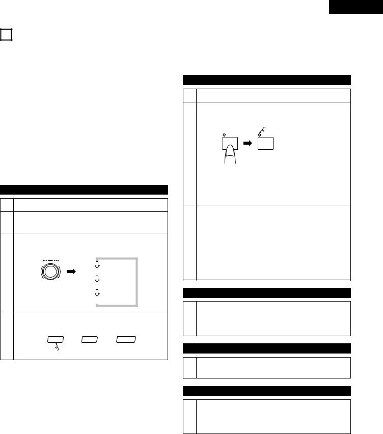
ENGLISH
9SAMPLER/DIGITAL SCRATCH/EFFECTOR
DN-2600F’s ASP (Audio Signal Processor) has three modes - sampler, digital scratch and effector - that can be selected freely according to the purpose.
2Sampler
•The sound of the disc can be recorded/played for approximately 15 seconds.
•The recorded sound can be looped in the normal or reverse direction.
•The playing speed and level can be changed. In addition, the key adjust function makes it possible to keep the key constant even when the playing speed is changed.
2Digital scratch
•The jog dial can be used to scratch with a feeling similar to when scratching with an analog player.
2Effector
•Three different effect functions can be used to create original sounds. (In the effector mode, the playing level is 6dB lower than the normal playing level.)
Selecting the ASP mode
1Set the stop mode.
2Set the ASP operation selection mode.
Press the MODE button.
Select the sampler, digital scratch or effector mode.
Turn the data master knob (8—9).
|
PUSH ENTER |
3 |
Sampler? |
|
D-Scratch? |
|
Effector? |
Set the mode you want to operate.
Press the data master knob (8—9).
4 |
SAMP or |
DIGI-S or EFFECT |
|
||
|
Lit |
|
(1) Sampler
Recording samples
1Set the ASP to the sampler mode.
Start recording.
Press the PLAY/WRITE button.
|
Lit |
ON/OFF |
ON/OFF |
PLAY/WRITE |
PLAY/WRITE Samp Write |
2-1
•The disc plays and the sound is recorded for approximately 15 seconds. (The STOP LED lights when recording is over.)
•Recording can be stopped before the 15 seconds is up by pressing the STOP button.
[Sampling the seamless loop]
•When the end point (B) is set for the start point (A), the standby mode is set at the start point (A) and recording is started, recording stops at the end point (B). (During
2-2 |
recording, “Samp Load-B” is displayed on the character |
|
display.) |
||
|
•If the section between points A and B is more than 15 seconds long, recording stops after 15 seconds.
For instructions on setting the standby mode at point A, refer to “Fine-adjusting the start points” (page 16).
Playing the sampled sound
Press the PLAY/WRITE button.
3• Playback of the sampled sound starts.
•The stop mode is set automatically once the end of the recording is reached.
Stopping sampler playback
4Press the STOP button.
• Sampler playback stops.
Clearing the recorded sample
|
Press the STOP button for at least 2 seconds. |
|
5 |
• The recorded sample is cleared. |
|
The sampler playback parameters and the LOOP and RVS |
||
|
||
|
settings are reset to the default values. |
17
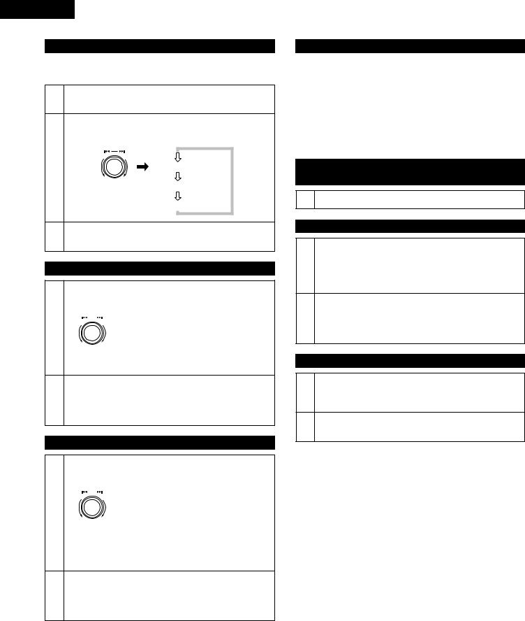
ENGLISH
Selecting the sampler playback parameter
The playing pitch, playback level and key adjust mode can be selected.
1Set the sampler playback parameter selection mode.
Press the FLG/PITCH button.
Select the pitch, level or key adjust mode.
Turn the data master knob (8—9).
|
PUSH ENTER |
2 |
SAMP Pitch? |
|
SAMP Level? |
|
SAMP Key.? |
3Set the mode whose parameter you want to change.
Press the data master knob (8—9).
Changing the sampler playing pitch
After setting the parameter to “sampler pitch”, turn the data master knob (8—9).
|
PUSH ENTER |
||
4-1 |
|
|
Turn the knob clockwise to increase the |
|
|
||
|
|
sampler playing speed, counterclockwise to |
|
|
|
|
decrease it. |
•The speed changes by 0.5% for each click of the knob. (The adjustment range is ±16%.)
|
[Canceling the sampler pitch mode] |
4-2 |
Press the data master knob (8—9). |
|
• The player returns to the same status as in step 2 and |
|
other parameters can be changed. |
Changing the sampler playback level
After setting the parameter to “sampler level”, turn the data master knob (8—9).
|
PUSH ENTER |
||
|
|
|
Turn the knob clockwise to increase the |
|
|
|
|
5-1 |
|
|
sampler playback level, counterclockwise |
|
|
to decrease it. |
|
•The level can be set in five steps.
NOTE:
•Depending on the recording level, clipping may occur in the playback sound if the playback level is increased.
|
[Canceling the sampler level mode] |
5-2 |
Press the data master knob (8—9). |
|
• The player returns to the same status as in step 2 and |
|
other parameters can be changed. |
Sampler key adjust setting
6-1 |
After setting the parameter to “key adjust”, turn the data |
|
master knob (8—9). |
||
|
• |
Turn key adjust on or off. |
|
|
|
|
[Canceling the sampler key adjust setting mode] |
|
6-2 |
Press the data master knob (8—9). |
|
|
• |
The player returns to the same status as in step 2 and |
|
|
other parameters can be changed. |
|
|
|
Canceling the sampler playback parameter selection mode
7 Press the FLG/PITCH button again.
Playing the sample backwards
Set the sampler reverse playback mode.
Press the FIL/REVERSE button.
1• After pressing the FIL/REVERSE button, press the PLAY/PAUSE button to start playing the sample backwards, starting from the end point.
[Canceling the sampler reverse playback mode]
2Press the FIL/REVERSE button again.
•After pressing the FIL/REVERSE button, press the PLAY/PAUSE button to resume normal sample playback.
Playing the sampler in a loop
Set the sampler loop playback mode.
1Press the RVB/LOOP button.
• The sample is played in a loop.
2[Canceling the sampler loop playback mode]
Press the RVB/LOOP button again.
18
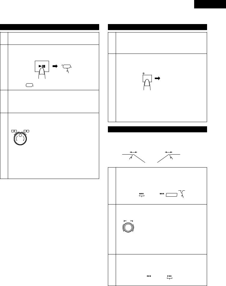
(2) Digital scratch
Using the scratch function
1Set the ASP to the scratch mode.
• Refer to “Selecting the ASP mode” on page 17.
Check that it is possible to start scratching.
Press the PLAY/PAUSE button.
|
PLAY / PAUSE |
2 |
GO! |
|
Lit |
• If the “  GO! ” indicator is lit, scratching is possible.
Set the jog dial to the scratch mode.
Press the EFFECT button so that the DIGI-S LED flashes or
3lights.
The DIGI-S LED lights when scratching is performed once.
Change the playing speed and direction of playback.
Turn the jog dial.
SEARCH |
|
The disc is played in the forward direction |
|
SCAN |
when the jog dial is turned clockwise, in |
||
I |
I |
§6 7 |
|
I |
|
|
|
|
|
|
the reverse direction when the jog dial is |
|
|
|
turned counterclockwise. |
4 |
|
|
The playing speed changes according to |
|
|
the speed at which the dial is turned. |
|
•Press the PLAY/PAUSE button during the scratch mode to pause in the PLAT-S mode.
•If the scratch operation is performed during normal playback, normal playback resumes once scratching is stopped.
•If the scratch operation is performed in the pause mode,
the pause mode is set once scratching is stopped.
ENGLISH
(3) Effector
Setting the effector mode
Set the ASP to the effector mode.
•Refer to “Selecting the ASP mode” on page 17.
1In the effector mode, the playing level is 6dB lower than the normal playing level.
After setting the effector mode, set the track’s BPM.
Press the TAP (TAP/BPM) button several times in beat with the music.
TAP
115bpm
2
•The track’s BPM is set according to the tempo at which the button is pressed.
•This tempo is set as the reverb and flanger operating time.
When the BPM is input after starting playback from the standby position or after hot starting, the BPM can be set individually for the different modes.
Using the filter function
With this function, the sound is filtered to reduce the low or high range frequencies.
0Hz |
20kHz |
Low range frequencies |
High range frequencies |
After setting the effector mode, set the filter low frequency input mode.
Press the FIL/REVERSE button.
1-1
L--H Freq.L
|
EFFECT |
Low range frequencies |
Flashing |
Select the low frequency range to be filtered.
Turn the data master knob (8—9).
|
PUSH ENTER |
The frequency increases when the knob is |
||
|
|
|
|
|
1-2 |
|
|
|
turned clockwise and decreases when the |
|
|
|
knob is turned counterclockwise. |
|
•The frequency can be set between 100 Hz and 20 kHz (or none).
It is not possible to set the low frequency to a frequency higher than the high frequency.
Set the filter high frequency input mode.
Press the data master knob (8—9).
2-1
Freq.H L--H
High range frequencies
19
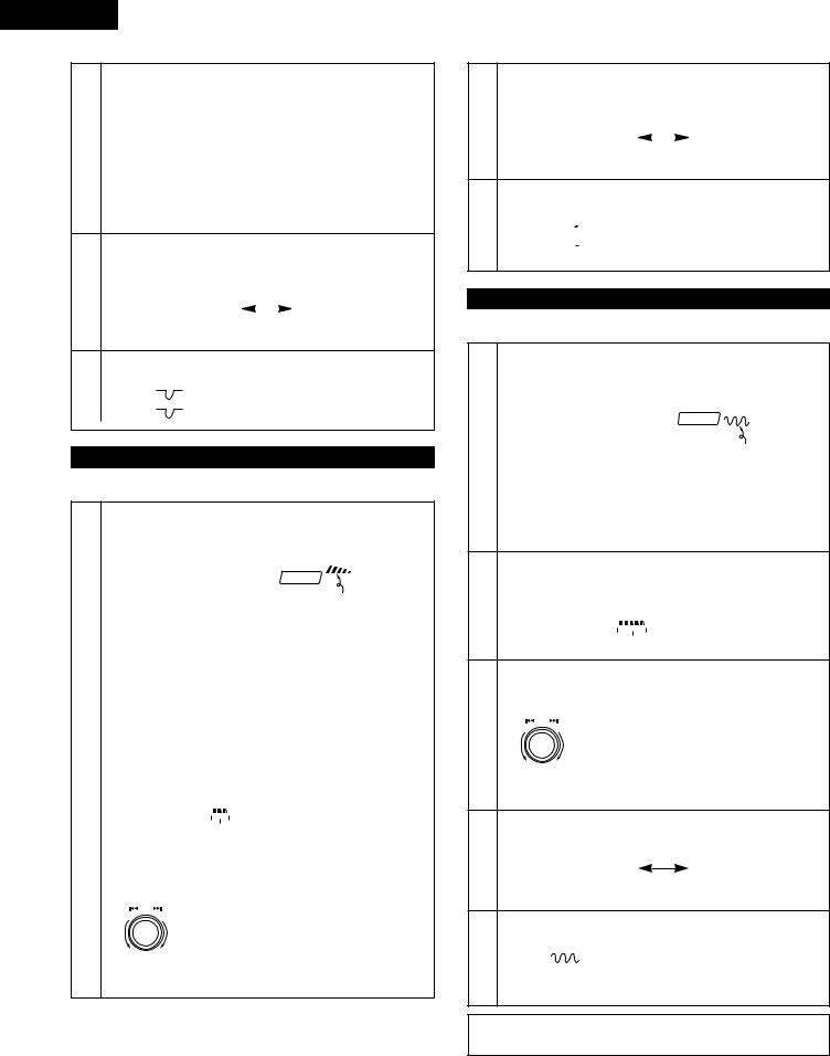
ENGLISH
Select the high frequency range to be filtered.
Turn the data master knob (8—9).
•If the data master knob (8—9) is pressed again, the player returns to the same status as in step 1-2.
•The frequency can be set between 100 Hz and 20 kHz (or
2-2 none).
The high frequency cannot be set below than the low frequency.
NOTE:
•For some tracks, clipping may occur in the playback sound.
Start filtered playback.
Press the ON/OFF button at any point between steps 1-1
and 2-2.
3
FIL ON |
|
FIL OFF |
|
• When pressed again, the filter turns off.
Canceling the filter frequency input mode.
4 |
Press the FIL/REVERSE button. |
||
• |
The “ |
” indicator is lit when the filter is on. |
|
|
• |
The “ |
” indicator is not lit when the filter is off. |
Using the reverb function
With this function, an echo is produced at the set tempo.
Set the reverb delay time input mode. |
||||||
Press the RVB/LOOP button. |
||||||
1-1 |
|
|
|
***bpm 1/2 |
||
|
|
|
|
|
|
EFFECT |
|
|
|
|
|
|
Flashing |
|
|
|
|
|
||
Select the reverb delay time. |
||||||
Turn the data master knob (8—9). |
||||||
1-2 |
|
|
|
|
***bpm 1/2 |
|
• |
The time can be set to 2/1, 1/1, 3/4, 1/2, 1/4 or 1/8 the |
|||||
|
BPM set with the TAP (TAP/BPM) button. |
|||||
|
|
|
|
|
||
Set the reverb feedback number mode. |
||||||
Press the data master knob (8—9). |
||||||
2-1 |
|
|
|
|
L F.Back H |
|
|
|
|
|
|
|
|
|
|
|
|
Feedback number |
||
|
|
|
|
|
||
Select the reverb feedback number. |
||||||
Turn the data master knob (8—9). |
||||||
|
PUSH ENTER |
The feedback number increases when the |
||||
2-2 |
|
|
|
|||
|
|
|
||||
|
|
|
knob is turned clockwise and decreases |
|||
|
|
|
|
when the knob is turned counterclockwise. |
||
•If the data master knob (8—9) is pressed again, the player returns to the same status as in step 1-2.
Start reverb playback.
Press the ON/OFF button at any point between steps 1-1
and 2-2.
3
RVB ON |
|
RVB OFF |
|
• When pressed again, reverb playback stops.
Canceling the reverb data setting mode.
Press the RVB/LOOP button.
4• The “ 
 ” indicator is lit when the reverb mode is on.
•The “ 
 ” indicator is not lit when the reverb mode is off.
Using the flanger function
With this function you can create swelling sounds.
Set the flanger time input mode.
Press the FLG/PITCH button.
1-1 |
***bpm 1/4 |
|
EFFECT |
||
|
||
|
Flashing |
|
|
|
|
|
Select the flanger time. |
|
1-2 |
Turn the data master knob (8—9). |
|
|
• The time can be set to 4/1, 2/1, 1/1, 3/4, 1/2, 1/4 or 1/8 |
|
|
the BPM set with the TAP (TAP/BPM) button. |
Set the flanger gain input mode.
Press the data master knob (8—9).
2-1 |
L Gain H |
|
|
|
|
|
Gain |
|
Select the flanger gain.
Turn the data master knob (8—9).
|
PUSH ENTER |
The gain increases when the knob is turned |
||
2-2 |
|
|
|
|
|
|
|
clockwise and decreases when the knob is |
|
|
|
|
|
turned counterclockwise. |
•If the data master knob (8—9) is pressed again, the player returns to the same status as in step 1-2.
Start flanger playback.
Press the ON/OFF button.
3 |
FLG ON |
FLG OFF |
• When pressed again, flanger playback stops.
Canceling the flanger data setting mode.
Press the FLG/PITCH button.
4 • The “ |
” indicator is lit when the flanger mode is on. |
•The “  ” indicator is not lit when the flanger mode is off.
NOTE:
• For some tracks, clipping may occur in the playback sound.
20
ENGLISH
10MEMO
Use this function to store the cue point, the pitch and the loop start point (A) and end point (B) in the memory and to call this data out.
Up to 300 sets of data, one set per track, can be stored in the memory.
The memory data can be copied between two RC-46s.
Storing data in the memory
Set the memo operation selection mode.
Set the player to the status you want to store in the memory, then press the MEMO button.
1
Memo Set?
•If there are already 300 sets of data in the memory, “Memo Full” is displayed and the data overwrite mode is set.
Store the data in the memory.
Press the data master knob (8—9).
2Memo No.***
•The “ MEMO ” indicator lights.
•The memo mode is canceled after 1 second.
Overwriting data
If there are already 300 sets of data in the memory,
select “Over Write?”.
3
Over Write?
Set the memory overwrite mode.
Press the data master knob (8—9).
4
Memo No.001
Select the data number you wish to overwrite.
Turn the data master knob (8—9).
5
Memo No.***
Display “Memo Set?”.
Press the MEMO button.
6
Memo Set?
Store the new data in the memory.
Press the data master knob (8—9).
7
Memo No.***
MEMO DATA COPY
Two units of the DN-2600F are required (one master, one slave).
Connect the RC-46 remote control signal transfer connectors (stereo mini jacks) with a cable as shown below.
1 |
|
Lch (Tip) |
(Tip) Lch |
|
RC-46 |
Rch (Ring) |
(Ring) Rch |
RC-46 |
|
|
|
|
||
|
GND |
|
|
GND |
|
(Sleeve) |
|
|
(Sleeve) |
2Either open all the disc holders for the two sets or remove all the discs.
Make presettings 14 and 15 and perform the memo
3copy operation.
(Refer to page 26 for the presettings.)
Calling out data
1Check that the “ MEMO ” indicator is lit at the track whose data you wish to call out.
2Set the memo operation selection mode.
Press the MEMO button.
Select “Memo Call?”.
Turn the data master knob (8—9).
3
Memo Call?
Set the memo data call mode.
Press the data master knob (8—9).
•When the cue point is stored in the memory, the cue point is search for and the standby mode is set.
4When the A point is stored in the memory, the data for the A point is loaded.
•“Loading (memory number)” is displayed on the character display while the data is being loaded, and “Complete!” is displayed once loading is finished.
Clearing data
1Set the standby mode at the track whose data you want to clear.
2Set the memo operation selection mode.
Press the MEMO button.
Select “Memo Clear?”.
Turn the data master knob (8—9).
3
Memo Clear?
Set the data clear mode.
Press the data master knob (8—9).
Complete!
4
•The data is cleared and the “ MEMO ” indicator turns off.
•All the data in the memory can be cleared at once using the “Memory All Clear” preset function (page 26).
21
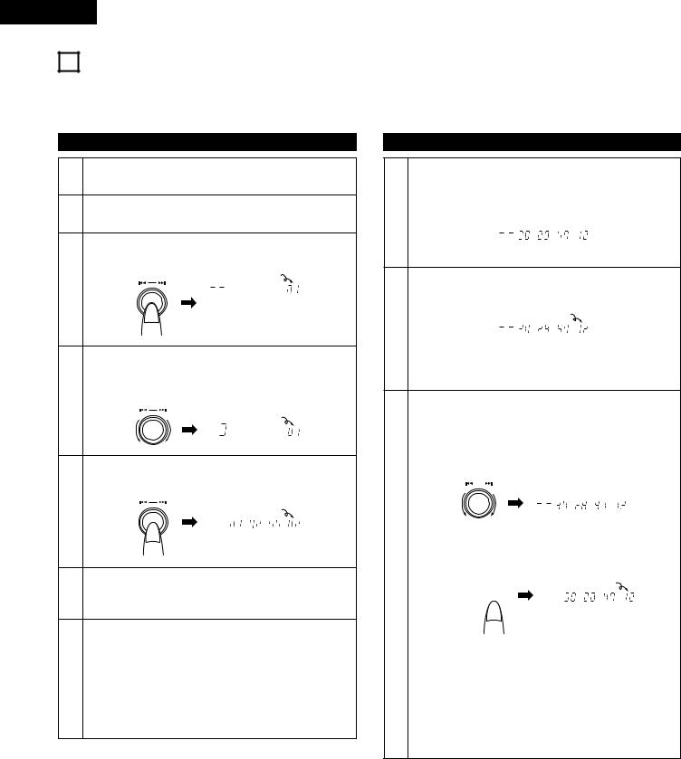
ENGLISH
11PROGRAMMED PLAYBACK
Use this function to program the tracks to play in a certain order.
Up to 25 tracks per disc can be programmed.
Programs for up to six discs can be stored in the permanent memory.
Inputting programs
1Set the program operation selection mode.
Press the PROGRAM button.
2Select “Program In?”.
Turn the data master knob (8—9).
Set the program input mode.
Press the data master knob (8—9).
PUSH ENTER |
|
Flashing |
|
3 |
m |
s |
f |
Select Tr?
Select the track you want to program.
Turn the data master knob (8—9). [Example: When track 3 is selected]
4
PUSH ENTER
Flashing
m |
s |
f |
Program the selected track.
Press the data master knob (8—9).
PUSH ENTER |
|
|
5 |
|
Lit |
m |
s |
f |
To program other tracks, repeat steps 3 to 5.
6“Program Full” appears on the character display if you attempt to program a 26th track.
[Canceling the program input mode]
Press the PROGRAM button.
•If no program has been input, the player returns to the normal status.
7• If a program has been input, the player returns to the program operation selection mode. (The player returns to the same status as in step 11.)
•If the PROGRAM button is pressed again, the player returns to the normal status.
Changing programs
[Changing programmed tracks]
Select the program step number you want to change.
Turn the data master knob (8—9).
8-1 |
[Example: To change program step number 12] |
|
|
m s |
f |
Change Tr?
Set the program step number to be changed.
Press the data master knob (8—9).
|
Flashing |
|
8-2 |
m s |
f |
Select Tr?
•The player is set to the same status as in step 4 and a new track can be selected.
[Inserting tracks in a program]
Select the program step number where you want to insert a track.
|
Turn the data master knob (8—9). |
|
|||||
9-1 |
[Example: To insert a track at program step number 12] |
||||||
|
|
PUSH ENTER |
|
|
|||
|
|
|
|
|
m |
s |
f |
|
|
|
|
|
|||
|
|
|
|
|
Change Tr? |
||
|
|
|
|
|
|
|
|
|
Set the program insert mode. |
|
|
||||
|
Press the PITCH BEND + button. |
|
|
||||
|
|
|
|
|
|
|
Flashing |
|
|
|
|
|
|
|
|
9-2 |
|
- |
|
+ |
|
m |
s f |
|
PITCH |
|
Insert Tr? |
||||
|
|
|
|||||
|
|
|
|
|
|||
|
• The player is set to the same status as in step 4 and an |
||||||
|
additional track can be selected. |
|
|
||||
|
|
|
|
|
|
|
|
10 |
[Clearing a programmed track] |
|
|
||||
-1 |
Select the program step number you want to delete. |
||||||
Turn the data master knob (8—9). |
|
||||||
|
|
||||||
|
|
|
|
|
|
|
|
10 |
Clear the step from the program. |
|
|
||||
-2 |
Press the PITCH BEND – button. |
|
|
||||
22
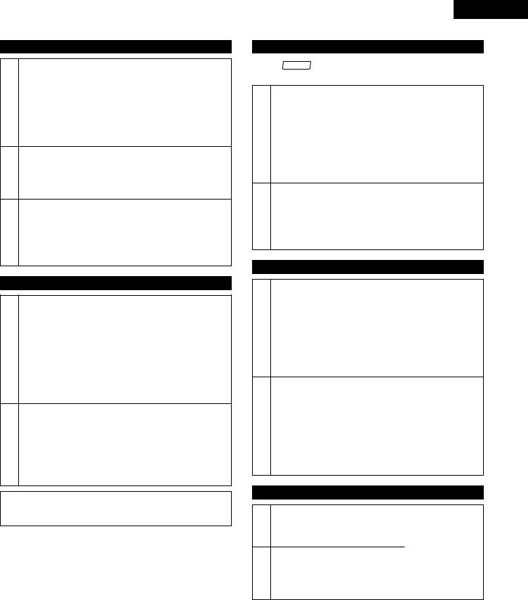
Playing programs
In the program operation selection mode, select “Program On?”.
Turn the data master knob (8—9).
11
Program On?
“Program On?” can only be selected when a program has been input.
Set the program play mode.
Press the data master knob (8—9).
12
Program 01
Start programmed playback.
Press the PLAY/PAUSE button.
13• The tracks are played in the programmed order in the currently set play mode.
•The repeat mode can be turned on and off by pressing the LOOP button.
Storing a program in the memory
In the program operation selection mode, select “P.Memo Set?”.
Turn the data master knob (8—9).
1P.Memo Set?
“P.Memo Set?” can only be selected when a program has been input.
“P.Memo Set?” cannot be selected if a program has already been stored in the memory for that disc.
Store the program in the memory.
Press the data master knob (8—9).
2 |
Complete! |
|
“P.Memo Full” is displayed on the character display if you attempt to store the program for a 7th disc in the memory.
NOTE:
•The loop, sampler, effector and scratch functions cannot be used in the program play mode.
ENGLISH
Calling out programs from the memory
The “ PROG. ” indicator lights when a disc for which a program is stored in the memory is loaded in the player.
In the program operation selection mode, select “P.Memo Call?”.
Turn the data master knob (8—9).
1P.Memo Call?
“P.Memo Call?” can only be selected when a program is stored in the memory for the disc that is currently loaded in the player.
Call out the program and set the program play mode.
Press the data master knob (8—9).
2
Program 01
• The standby mode is set at the first track in the program.
Clearing programs from the memory
In the program operation selection mode, select “P.Memo CLR?”.
Turn the data master knob (8—9).
1P.Memo CLR?
“P.Memo CLR?” can only be selected when a program is stored in the memory for the disc that is currently loaded in the player.
Clear the program.
Press the data master knob (8—9).
Complete!
2
•The program data is cleared and the player returns to the normal status.
•All the data in the memory can be cleared at once using the “Program All Clear” preset function (page 26).
Canceling program playback
Press the program button and select “Program Off?”.
1
Program Off?
Cancel program playback.
Press the data master knob (8—9).
2
Complete!
23
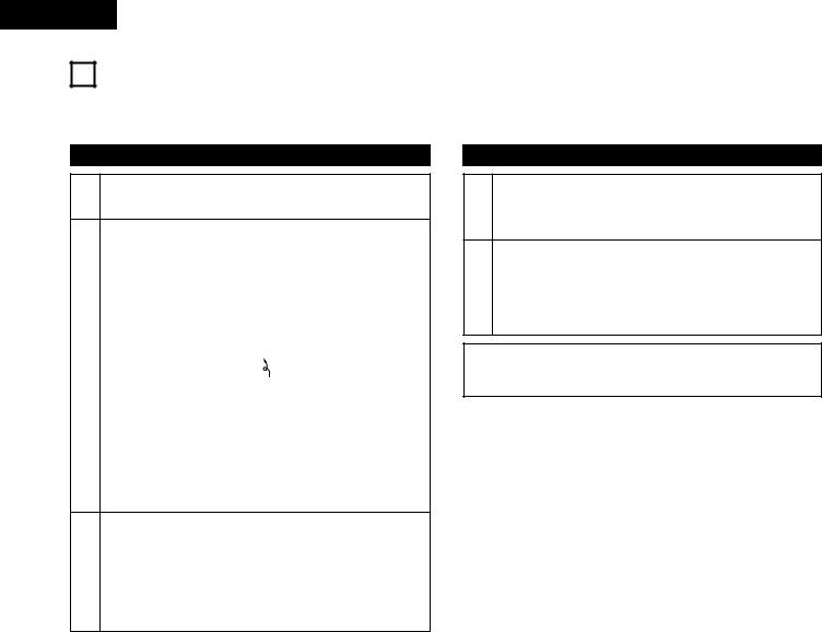
ENGLISH
12RANDOM PLAYBACK
Use this function to play the tracks in random order.
Random playback is performed for the discs in both disc holders.
Setting the random play mode
1Set the program operation selection mode.
Press the PROGRAM button.
Select “Random On?”.
2 |
Turn the data master knob (8—9). |
|
|
|
Random On? |
|
|
|
Set the random play confirmation mode. |
3 |
Press the data master knob (8—9). |
Random OK? |
|
|
Flashing |
|
|
|
Set the random play mode. |
|
Press the data master knob (8—9). |
4--Random--
•The standby mode is set at the first track to be played (in random order).
Start random playback.
Press the PLAY/PAUSE button for the disc holder whose CUE button is lit.
5• The playing mode is automatically set to the continuous play mode during random playback.
•The repeat mode can be turned on and off by pressing the LOOP button.
Canceling random playback
Press the program button and display “Random Off?”.
1
Random Off?
Cancel the random play mode.
Press the data master knob (8—9).
2The random play mode is also canceled when the disc holder for the disc which is set to the standby mode is opened.
NOTE:
•The loop, sampler, effector, scratch, Brake and Plat-S functions cannot be used in the random play mode.
24
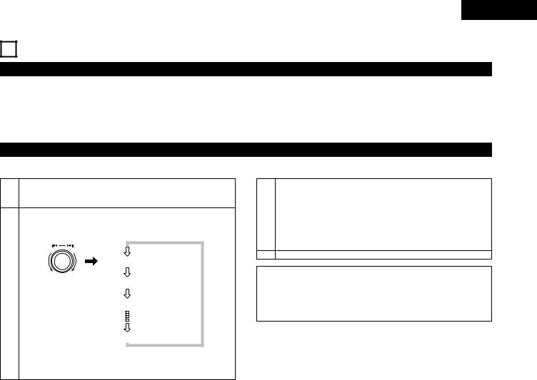
ENGLISH
13PRESET FUNCTIONS AND OPERATIONS
(1)Preset functions
Use these functions to preset the DN-2600F’s operation modes. These presettings are stored in a permanent memory, so they are not cleared even when the power is turned off.
The functions shown on the table on page 26 can be preset. Set these judiciously according to your usage purpose for more efficient operation.
(2)Presetting procedure
The presetting procedure can be performed in the cue or pause mode, when no disc is loaded or when the disc holder is open.
1Set the preset operation selection mode.
Press the PRESET button.
Select the preset item.
Turn the data master knob (8—9).
|
PUSH ENTER |
|
|
|
AutoCue ON |
|
Turn the knob clock- |
BK Time L |
2 |
wise to move in the |
|
direction of the |
|
|
|
EOM OFF |
|
|
arrows, counterclock- |
|
|
wise to move in the |
|
|
opposite direction. |
|
|
|
Preset Int? |
The first preset item displayed is the last preset item displayed the last time the presettings were mode.
Change the setting.
3Press the data master knob (8—9).
•When the data master knob (8—9) is turned, the player returns to the same status as in step 2.
4Cancel the preset mode.
Press the PRESET button.
NOTE:
•If the message shown below appears, there is a problem with the preset memory. Contact a serviceperson.
Eeprom Error
25

ENGLISH
(3) Detailed Description of Preset Functions
(“*” indicates the default setting.)
(1)Auto Cue ON/OFF
*“AutoCue ON” : The cue point is detected at a sound level of –54 dB. “AutoCue OFF” : Cue detection is not performed.
(2)Brake Time: Set the operating time for the BRAKE and PLAT-S modes.
“BK Time S” |
: |
Short |
”BK Time N” |
: |
Normal |
* “BK Time L” |
: |
Long |
(3)E.O.M
*”EOM OFF” : No end of message is emitted.
“EOM (setting time) sec” : Set the end of message time. (10, 15, 20, 30, 60 or 90)
(4)Pitch Range
“Pitch (setting value) %” : Select the pitch adjustment range (16, *10).
(5)End Monitor
“EndMon (setting time) sec” : Set the end monitor time (*10, 20, 30 or 60).
(6)Play Mode: Set the play mode which is set when the power is turned on.
* ”Single” |
: |
Playback ends at the end of the track. |
“Continuous” |
: |
Playback continues until the end of the disc. |
(7)Time Mode: Set the time mode which is set when the power is turned on.
* ”Elapsed” |
: The elapsed time per track is displayed. |
|
“Remain” |
: The remaining time per track is displayed. |
|
“T.Elapsed” |
: |
The elapsed time per disc is displayed. |
“T.Remain” |
: |
The remaining time per disc is displayed. |
(8)ASP Mode: Set the mode to which the ASP is set when the power is turned on.
* ”Sampler” |
: |
Sampler mode |
“DigiScratch” |
: |
Digi-Scratch mode |
“Effector” |
: |
Effector mode |
(9)Auto Close: Set the disc holder auto close mode.
|
“Close OFF” |
: The disc holders do not close automatically. |
|
|
“Close (setting time) sec” |
: Set the time from which the disc holder is opened until it is closed automatically (10, *30 or 60). |
|
(10) |
Sleep Mode: If no operation is performed in the pause or cue mode, the motor stops and the stop mode is set after a specific amount of |
||
|
time. |
|
|
|
“Sleep (setting time) min” |
: |
Set the time after which the sleep mode is set (*30, 20 or 10). |
(11) |
Digital Out |
|
|
|
“DigiOut ON” |
: |
Digital data is output. (NOTE: The operable functions are limited.) |
|
* ”DigiOut OFF” |
: Digital data is not output. |
|
(12) |
Program All Clear: Use this to clear all the program data stored in the memory. |
||
q“Clear OK?” is displayed when the data master knob is pressed when “ProgAll Clr?” is displayed. w When the data master knob is pressed again, “PrgAll Clr” is displayed and the data is cleared.
e “Complete!” is displayed 1 second after the data has been cleared.
(13)Memory All Clear: Use this to clear all the memo data stored in the memory.
q“Clear OK?” is displayed when the data master knob is pressed when “MemoAllClr?” is displayed. w When the data master knob is pressed again, “MemoAllClr” is displayed and the data is cleared. e “Complete!” is displayed 1 second after the data has been cleared.
(14)Signal transfer between remote control units: When two remote control units are connected, select the master and slave. “Copy Master” : The memory is copied from this side.
“Copy Slave” : The memory is copied to this side.
* ”Copy Off” |
: The memory is not copied. |
(15)RC Memo All Copy: Copy the memory data from the master to the slave when two remote control units are connected. [Slave side]
q “Slave Mode” is displayed when the data master knob is pressed when “Memo Copy?” is displayed. w “Copy OK?” is displayed when the data master knob is pressed again.
e “Memo Copy” is displayed when the data master knob is pressed again and the data copy standby mode is set. r “Complete!” is displayed 1 second after the data transferred from the master side has been copied.
[Master side]
q “Master Mode” is displayed when the data master knob is pressed when “Memo Copy?” is displayed. w “Copy OK?” is displayed when the data master knob is pressed again.
e “Memo Copy” is displayed when the data master knob is pressed again and the data is transferred. (“Not Connect” flashes if the two remote control units are not connected or if the slave side is not in the copy standby mode.)
r “Complete!” is displayed 1 second after the data has been transferred.
(16)Preset Clear: This restores the preset data to the factory default values.
q “Initial OK?” is displayed when the data master knob is pressed when “Preset Int?” is displayed. w “Preset Int” is displayed when the data master knob is pressed again and the data is initialized. e “Complete!” is displayed 1 second after initialization is completed.
26

ENGLISH
14 CLEANING THE OPTICAL PICK–UP LENS
Necessity of cleaning might be differed on location and frequency of use each player.
It is recommend to clean the pick–up lens once a week.
We recommend using DENON’s AMC–22 PICK–UP LENS CLEANER.
15 SPECIFICATIONS
GENERAL |
|
|
|
Type: |
Twin mechanism compact disc player with wired remote control |
||
Disc type: |
Standard compact discs (12 cm and 8 cm discs) |
|
|
Dimensions: |
Player unit: |
482 (W) x 88 (H) x 252 (D) mm (without feet) |
|
|
|
18-31/32” (W) x 3-15/32” (H) x 9-59/64” (D) |
|
|
Remote control unit: |
482 (W) x 132 (H) x 40 (D) mm (without feet) |
|
|
|
18-31/32” (W) x 5-13/64” (H) x 1-37/64” (D) |
|
Installation: |
19-inch rack mountable |
|
|
|
Player unit: |
2U |
|
|
Remote control unit: |
3U |
|
Weight: |
Player unit: |
6 kg (13.23 lbs.) |
|
|
Remote control unit: |
3 kg (6.614 lbs.) |
|
Power supply: |
U.S.A., Canada and Taiwan R.O.C. models: 120 V AC |
±10%, 60 Hz |
|
|
European models: |
230 V AC |
±10%, 50 Hz |
Power consumption: |
26 W |
|
|
Environmental conditions: |
Operational temperature: |
5 to 35°C |
(41 to 95°F) |
|
Operational humidity: |
25 to 85% (no condensation) |
|
|
Storage temperature: |
–20 to 60°C |
(4 to 140°F) |
AUDIO SECTION |
|
|
|
Quantization: |
16-bit linear per channel |
|
|
Sampling frequency: |
44.1 kHz at normal pitch |
|
|
Oversampling rate: |
8 times |
|
|
Frequency response: |
20 to 20,000 Hz |
|
|
Analog output |
|
|
|
Output level: |
1.9 V |
|
|
Digital output |
|
|
|
Signal format: |
SPDIF |
|
|
Output level: |
0.5 Vp-p 75 Ω/ohms |
|
|
Load impedance: |
10 kΩ/kohms or more |
|
|
FUNCTIONS |
|
|
|
Instant start: |
Within 20 msec. |
|
|
Variable pitch: |
10% range: |
±10% or more |
|
|
16% range: |
±16% or more |
|
Pitch bend: |
±32% or more |
|
|
Sampling length: |
15 sec. |
|
|
Search precision: |
1/75 sec. (1 subcode frame) |
|
|
Max. scan speed: |
Over 20 times normal speed |
|
|
Max. memory steps: |
300 steps |
|
|
Specifications and design are subject to change without notice for purpose of improvement.
27

DEUTSCH
— INHALT —
z Hauptausstattungsmerkmale………………………………………28
x Anschlüsse/Installation ……………………………………………28
c Bezeichnung der teile und deren funktionen ………………29 ~ 32 v CD–platten …………………………………………………………32
b Grundlegender betrieb ……………………………………………33
nWiedergabe-Geschwindigkeit/Brems-/Plattenteller- /Tonart- Steuerung ……………………………………………………………34
m Reservierung des nächsten titels ………………………………35
, Nahtlose schleife/Sofortstart/Stottern ………………………36, 37
. Sampler/Digital-scratch/Effektor ……………………………38 ~ 41
⁄0Memo ………………………………………………………………42
⁄1Programmierte wiedergabe……………………………………43, 44
⁄2Zufallswiedergabe …………………………………………………45
⁄3Voreingestellte funktionen und operationen ………………46, 47 ⁄4Reinigung der optischen aufnahmelinse …………………………48
⁄5Technische daten ……………………………………………………48
• ZUBEHÖR
Stellen Sie sicher, daß die nachfolgend aufgeführten Zubehörteile dem Hauptgerät beiliegen:
q Bedienungsanleitung ……………………………………………1 |
e Fernbedienungsgerät (RC-46) ……………………………………1 |
w Anschlußkabel für den Signalausgang (RCA) …………………2 |
r Fernbedienungs–Anschlußkabel …………………………………1 |
|
|
1 HAUPTAUSSTATTUNGSMERKMALE
Bei dem DN-2600F handelt es sich um einen mit einer Vielzahl von Funktionen ausgestatteten Doppel-CD-Spieler mit reichhaltigen Leistungseigenschaften. Das Gerät eignet sich z. B. hervorragend zum DJ-Mixen und Neumixen.
Bedienung
1.Der DN-2600F lässt sich problemlos in ein 19-Inch-Rack einbauen.
2.Verbesserte Sicht dank eines großen FL-Displays, selbstleuchtender Tasten und Disc-Halter-Beleuchtung.
3.Verbesserte Bedienung dank einer großen Jog-/Shuttle- Scheibe und Titelwahlknopf.
Funktionen
1.Erschütterungsschutz-Funktion zum Schutz vor externen Erschütterungen
2.Automatischer Pegelsuchlauf / Sofortstart
3.Veränderung der Wiedergabe-Geschwindigkeit (Taste & Jog)
4.Nahtlose Schleifenwiedergabe
Die Wiedergabe kann ohne Tonunterbrechung zwischen zwei beliebigen Positionen umgeleitet werden. Sie können zwei Schleifen-Startpunkte (A-1 und A-2) einstellen.
5.Sofortstart / Stotter-Modus
Die Wiedergabe kann sofort von den Punkten A-1 und A-2 gestartet werden. Im Stotter-Modus wird die Disc nur während der Betätigung einer Taste wiedergegeben.
6.Sampler
Jede CD kann ca. 15 Sekunden lang wiedergegeben werden. Während dessen können die nachfolgend aufgeführten Funktionen angewendet werden: Schleife, Reverse, Einstellung der Wiedergabe-Geschwindigkeit, Wiedergabepegel-Einstellung und Tonart-Einstellung.
7.Digital-Scratch
Diese Funktion erlaubt Scratchen ähnlich wie bei analogen Discs.
2ANSCHLÜSSE/INSTALLATION
1.Schalten Sie den Netzschalter (POWER) aus.
2.Verbinden Sie die RCA–Pin–Anschlüsse mit den Eingängen auf Ihrem Mischer.
3.Schließen Sie das Steuerungskabel an den REMOTE Anschluß am RC–46 an.
VORSICHT:
•Stellen Sie sicher, daß Sie das mitgelieferte Steuerungskabel benutzen. Die Anwendung eines anderen Kabels kann zu Schäden führen.
•Stellen Sie sicher, daß der Strom ausgeschaltet ist, wenn Sie das Steuerungskabel anschließen. Anderenfalls funktionieren die Geräte möglicherweise nicht korrekt.
•Schließen Sie niemals andere Fernbedienungsgeräte als das RC46 an, da dies eine Beschädigung des Gerätes verursachen könnte.
18. Effektor (Filter, Echo, Flanger)
Für die Erstellung einer Vielzahl von Effektsounds stehen drei verschiedene Effektor-Funktionen zur Verfügung.
19. Bremse / Plattenteller
Die Wiedergabe-Geschwindigkeit kann langsam gesenkt werden, um Audio-Discs auf ähnliche Weise wie analoge Schallplatten wiederzugeben und zu stoppen.
10.Nächster TitelReverse
Der nächste Titel der Wiedergabe kann angewählt werden, so dass die Wiedergabe ohne Tonunterbrechung fortgesetzt wird.
11.Memo
Bis zu 300 Datensätze wie z.B. der Cue-Punkt, die Schleifenpunkte A/B und die Wiedergabe-Geschwindigkeit können in einem Permanentspeicher abgelegt werden (ein Datensatz pro Titel).
12.Tonart-Steuerung / Tonart-Einstellung
Tonart–Steuerungsfunktion zum Einstellen der Wiedergabe–Tonart. Darüber hinaus kann die Tonart automatisch eingestellt werden, wenn sich die Wiedergabe-Geschwindigkeit so ändert, dass die Tonart gleich bleibt.
13.Endüberwachung
Die Titelenden können überwacht werden.
14.Programm- / Zufallswiedergabe
Es können bis zu 25 Titel programmiert werden und Programme für bis zu sechs Discs können in einem Permanentspeicher gespeichert werden. Die Zufallswiedergabe wird für die Discs in beiden Disc-Haltern ausgeführt.
15.Fader–Eingang
16.Servo–Autostoppfunktion für den Spindelmotor / Automatisches Schließen des Disc-Halters
17.Vorwahlfunktion zum Einstellen von auf den Verwendungszweck angepaßten Funktionen.
15°
Die DN–2600F Abspieleinheit kann von waagerecht bis zu einem Frontplatten– Neigungswinkel von 15° montiert werden ohne irgendwelche Funktionen zu beeinträchtigen. Bei einem Einbauwinkel von mehr ale 15° wird die CD vom Player möglicherweise nicht korrekt eingelegen.
DN-2600F
28
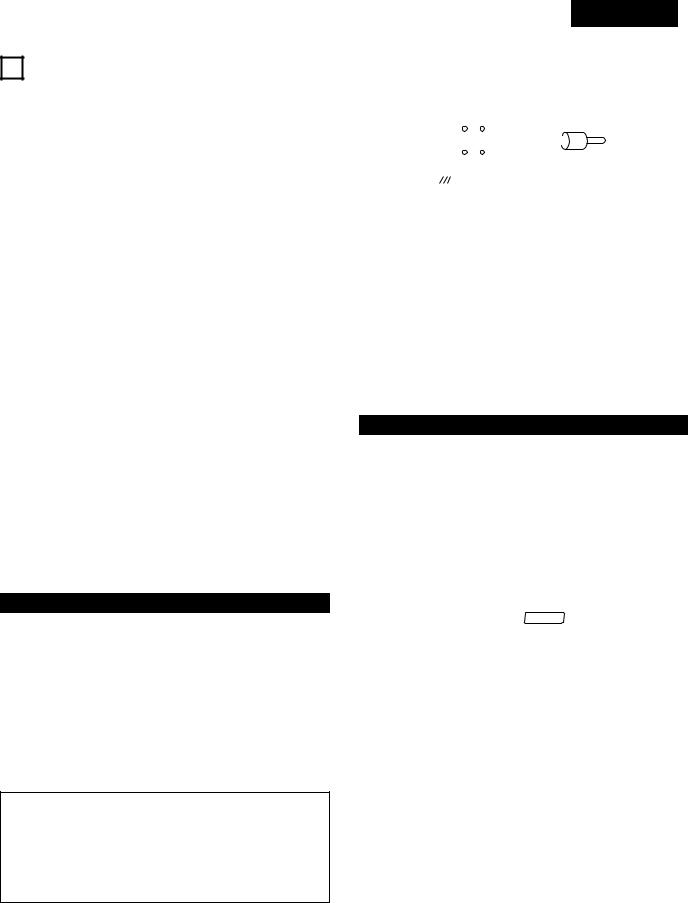
DEUTSCH
3 BEZEICHNUNG DER TEILE UND DEREN FUNKTIONEN
(1) Vorderseite des DN-2600F |
|
• Der Fader kann mit Hilfe des im nachfolgenden Diagramm |
|||||||||||||||
|
gezeigten Schalterstromkreises aktiviert werden. |
||||||||||||||||
q |
Netztaste (POWER) ( ON |
|
OFF) |
||||||||||||||
|
|
|
|
|
|
|
|
|
|
|
|
|
|
||||
|
|
¢ |
£ |
|
|
|
|
|
|
|
|
|
|
SW 1 |
Lch |
||
|
• |
Drücken Sie diese Taste, um das Gerät einzuschalten. |
|
|
|
|
|
|
|
|
|
SW 2 |
|
|
|
||
|
|
|
|
|
|
|
|
|
|
|
|
|
|||||
HINWEIS: |
|
|
|
|
|
|
|
|
|
|
|
|
GND |
||||
• |
Schließen Sie vor dem Ausschalten des Gerätes unbedingt |
|
|
|
GND* |
|
|
|
|||||||||
|
den Disc-Halter. |
|
|
|
|
|
|
|
|
||||||||
w Netzanzeige (POWER) |
|
|
• Schließen Sie SW1 an die “Lch”-Stereo-Minibuchse an. |
||||||||||||||
|
|
• Schließen Sie SW2 an die “GND”-Stereo-Minibuchse an. |
|||||||||||||||
|
• |
Diese Anzeige leuchtet, wenn das Gerät eingeschaltet ist. |
• Schließen Sie GND* an die analoge Ausgangsbuchse “GND” |
||||||||||||||
e Disc-Halter |
|
|
an. |
|
|
|
|||||||||||
|
|
• Verwenden Sie nicht die “Rch”-Buchse. |
|||||||||||||||
|
• |
Legen Sie die Discs in diesen Halter ein. |
• Bei Betätigung von SW1 startet der mit den A1und A2- |
||||||||||||||
|
• |
Drücken Sie zum Öffnen und Schließen des Disc-Halters die |
Tasten angewählte Sofortstart-Wiedergabemodus. |
||||||||||||||
|
|
OPEN/CLOSE-Taste. |
|
|
• Bei Betätigung von SW2 stoppt der Sofortstart- |
||||||||||||
|
|
|
|
|
Wiedergabemodus. |
|
|
|
|||||||||
VORSICHT: |
|
|
|
|
|
||||||||||||
|
|
Laden Sie die Sofortstart-Daten vor dem Starten der Fader- |
|||||||||||||||
• |
Legen Sie keine Fremdgegenstände in den Disc-Halter, da |
Wiedergabe. |
|
|
|
||||||||||||
|
diese eine Beschädigung des CD-Spielers verursachen |
|
|
|
|
|
|
|
|
|
|
|
|
|
|||
|
könnten. |
|
|
o Fernbedienungsanschluss (REMOTE) |
|||||||||||||
• |
Schieben Sie das Discfach bei abgeschalteter Stromzufuhr |
||||||||||||||||
|
nicht mit der Hand hinein, da dies zu Störungen führt und |
• Verbinden Sie diesen Anschluß über das beiliegende |
|||||||||||||||
|
das Gerät beschädigen kann. |
|
|
Steuerungs–Kabel mit dem RC–46. |
|||||||||||||
|
|
|
|
|
|
|
|
|
|
|
|
|
|
|
|
|
|
r Disc-Halter-LED
•Diese Anzeige blinkt während des Öffnens und Schließens des Disc-Halters.
•Das LED leuchtet, wenn der Disc-Halter geöffnet ist und dient gleichzeitig als Disc-Halter-Beleuchtung.
t Disc-Halter Öffnen-/Schließen-Taste (OPEN/CLOSE)
•Drücken Sie diese Taste zum Öffnen und Schließen des DiscHalters.
•Der Disc-Halter läßt sich während der Wiedergabe nicht öffnen. Beenden Sie vor Betätigung dieser Taste die Wiedergabe.
(2)Rückseite des DN-2600F
y Analoge Ausgangsbuchsen 1, 2
(ANALOG OUT 1, 2)
•Hierbei handelt es sich um unsymmetrische Ausgangsbuchsen, von denen die Audiosignale von CDSpielern ausgegeben werden.
u Digitale Ausgangsbuchsen 1, 2
(DIGITAL OUT 1, 2)
•Von diesen Buchsen werden entsprechend der Voreinstellungen digitale Daten ausgegeben.
•Wir empfehlen, ein 75 Ω/Ohm Stiftkabel (in Läden erhältlich) für Anschlüsse zu verwenden.
HINWEISE:
•Den PITCH-Regler auf OFF drehen, wenn Digitalaufnahmen gemacht werden. Die meisten Digtalrekorder akzeptieren kein variabel abgestimmtes Signal.
•Bei der Ausgabe digitaler Daten sind die Funktionen eingeschränkt. (Die Funktionen Schleifenwiedergabe, Bremstaste, Plat, Bend-Jog, Scratch, Sampler, Effektor und Tonart-Steuerung sind nicht verfügbar.)
iFader-Eingangsbuchsen 1, 2 (FADER 1, 2)
•Für die Benutzung des Gerätes mit einem Überblendregler. (Mini–Buchse)
(FADER INPUT LEVEL HCMOS (Ii=–3mA))
(3) Vorderseite des RC-46
!0Effekttaste (EFFECT)
•Drücken Sie diese Taste, um den Jog-Scheiben- Betriebsmodus anzuwählen.
Pitch Bend-Modus (Einstellung der WiedergabeGeschwindigkeit):
Bei Drehen der Jog-Scheibe ändert sich die WiedergabeGeschwindigkeit in festgelegten Werten. (Das BEND LED leuchtet.)
PLAT-H-Modus (Individuelle Einstellung der WiedergabeGeschwindigkeit):
Bei Drehen der Jog-Scheibe ändert sich die WiedergabeGeschwindigkeit entsprechend der Geschwindigkeit, mit der die Jog-Scheibe gedreht wird.
(Das BEND LED und die “ PLAT-H ”-Anzeige leuchten.)
Tonart-Modus:
Die Tonart kann durch Drehen der Jog-Scheibe eingestellt werden. (Das KEY LED leuchtet.)
Scratch-Modus:
Das Scratching ist durch Drehen der Jog-Scheibe möglich.
!1Suchlauftaste (SEARCH)
•Wenn Sie diese Taste drücken, während der JogScheibenBetriebsmodus auf den Pitch Bend-, PLAT-H-, Tonartoder Scratch-Modus eingestellt ist, wird der Jogund Shuttle- Scheiben-Suchlaufmodus eingestellt.
!2Shuttle-Scheibe (Außenseite)
•Die Shuttle-Scheibe kann im Suchlaufmodus benutzt werden.
•Wählen Sie mit Hilfe der Shuttle-Scheibe die Suchlaufrichtung und Geschwindigkeit aus.
•Die CD wird in Vorwärtsrichtung abgetastet, wenn Sie die Shuttle–Scheibe von der neutralen Position aus gesehen, im Uhrzeigersinn drehen. Die Abtastung in Rückwärtsrichtung wird durchgeführt, wenn Sie die Shuttle–Scheibe entgegen des Uhrzeigersinns drehen.
•Die Abtastgeschwindigkeit erhöht sich, indem Sie die Scheibe weiterdrehen.
29

DEUTSCH
!3Jog-Scheibe (Innenseite)
•Drehen Sie diese Scheibe im Suchlaufmodus während des Suchlaufbetriebes, um die Wiedergabeposition in Einheiten oder Feldern zu verschieben.
•Drehen Sie diese Scheibe im Pitch Bendoder PLAT-H- Modus, um die Wiedergabe-Geschwindigkeit zu verändern.
•Drehen Sie diese Scheibe im Tonart-Modus, um die Tonart einzustellen.
•Drehen Sie diese Scheibe für das Scratching im ScratchModus.
!4Filter-/Reverse-Taste (FIL/REVERSE)
•Drücken Sie diese Taste im Sampler-Modus, um den Modus für die Sampler-Reverse-Wiedergabe einund auszuschalten.
•Drücken Sie diese Taste im Effektor-Modus, um den Filterparameter-Eingangsmodus einzustellen.
!5Echo-/Schleifentaste (RVB/LOOP)
•Drücken Sie diese Taste im Sampler-Modus, um den Modus zur Sampler-Schleifenwiedergabe einund auszuschalten.
•Drücken Sie diese Taste im Effektor-Modus, um den Echoparameter-Eingangsmodus einzustellen.
!6TAP (TAP/BPM)/STOP Taste
(TAP (TAP/BPM)/STOP)
•Drücken Sie diese Taste im Sampler-Modus, um die SamplerAufnahme/Wiedergabe zu beenden.
•Drücken Sie diese Taste im Sampler-Modus für länger als 2 Sekunden, um die Sampler-Daten zu löschen.
•In den übrigen Fällen wird das Tempo der Tastenbetätigung gemessen und als BPM eingegeben. Wird die Taste nur einmal gedrückt, wird die BPM-Anzahl angezeigt.
!7Taste zum Spulen mit Ton (CUE)
•Wenn Sie die CUE–Taste während der Wiedergabe drücken, setzt sich das Gerät genau an die Position zurück, an der mit der Wiedergabe begonnen wurde. Wenn Sie alternativ die Wiedergabe–/Pausentaste (PLAY/ PAUSE) und die CUE–Taste drücken, wird die CD–Platte beliebig oft von der selben Position aus an wiedergegeben.
•Die Taste leuchtet, wenn der Standby-Modus eingestellt ist.
•Im Schlafmodus den Schlafmodus aufheben.
!8Flanger-/Wiedergabe-Geschwindigkeitstaste (FLG/PITCH)
•Drücken Sie diese Taste im Sampler-Modus, um den Samplerparameter-Eingangsmodus einzustellen.
•Drücken Sie diese Taste im Effektor-Modus, um den FlangerEingangsmodus einzustellen.
!9Wiedergabe-/Pausetaste (PLAY/PAUSE) (13)
•Benutzen Sie diese Taste um mit der Wiedergabe zubeginnen.
•Drücken sie einmal um die Wiedergabe zu beginnen, ein zweites Mal um in den Pause–Modus zu gehen und nocheinmal um die Wiedergabe fortzusetzen.
•Drücken Sie diese Taste im Bremsmodus zum Bremsen der Disc.
@0Ein-/Aus (ON/OFF), Wiedergabe-/Schreibtaste
(PLAY/WRITE)
•Drücken Sie diese Taste im Sampler-Modus, um die SampleAufnahme/Wiedergabe zu starten.
•Drücken Sie diese Taste, um die verschiedenen Effektoren einund auszuschalten.
@1Voreinstell-Taste (PRESET)
•Diese Sie diese Taste einmal drücken, um den VoreinstellEingangsmodus zu aktivieren.
Diese Taste nochmals drücken, um den VoreinstellEingangsmodus zu deaktivieren.
@2Modustaste (MODE)
•Bei Betätigung dieser Taste wird der ASPBetriebswahlmodus eingestellt.
@3Titelwahl-/Daten-Masterknopf (8–9/PUSH ENTER)
•Wählen Sie durch Drehen dieses Wahlschalters den nächsten Titel an, der/die wiedergegeben werden soll.
•Drehen Sie den Wahlschalter um einen Klick im Uhrzeigersinn, um jeweils an den nächsten Titel zu gelangen und drehen Sie ihn um einen Klick entgegen dem Uhrzeigersinn, um den jeweils davorliegenden Titel anzuwählen.
•Wird der Knopf gleichzeitig gedrückt und gedreht, entspricht ein Klick 10 Titeln.
•Im Speichermodus können Sie mit Hilfe dieses Wahlschalters Einstellungen eingeben.
•Bei der Einstellung von Programmen können Sie mit diesem Wahlschalter Programme anwählen, eingeben und überprüfen.
•Drücken Sie diesen Knopf im Memo-Modus zum Einstellen , zur Eingabe von Einstellungen, zur Überprüfung sowie zum Löschen von Einstellungen.
•Mit diesem Knopf wird der ASP-Betriebsmodus angewählt und Daten in verschiedenen Modi eingestellt.
@4Tonstärke-Regler
•Stellen Sie mit diesem Schieberegler die WiedergabeGeschwindigkeit ein.
•Die Wiedergabe-Geschwindigkeit verlangsamt sich, wenn Sie den Schieberegler nach oben schieben und erhöht sich beim Schieben nach unten.
@5Taste zur Erhöhung der WiedergabeGeschwindigkeit (PITCH BEND +)
•Bei Betätigung dieser Taste erhöht sich die WiedergabeGeschwindigkeit.
•Wenn Sie die Taste loslassen, wird wieder die vorherige Wiedergabe-Geschwindigkeit eingestellt.
@6Tonart-Steuerungstaste (KEY)
•Bei Betätigung dieser Taste wird der Tonart-Modus eingestellt und die Tonart kann mit der Jog-Scheibe eingestellt werden.
•Bei erneuter Betätigung wird der Tonart–Einstellmodus eingeschaltet; die Tonart bleibt auch bei Veränderung der
Tonhöhe unverändert (KEY ADJUST).
@7PITCH-Taste
•Drücken Sie diese Taste, um zu der mit dem Geschwindigkeitsregler eingestellten Wiedergabegeschwindigkeit umzuschalten. Das PITCH LED blinkt.
•Bei nochmaliger Betätigung dieser Taste wird der festgelegte Geschwindigkeitsmodus eingestellt und das PITCH LED leuchtet.
•Drücken Sie diese Taste noch einmal, um den Modus für die Wiedergabe mit hoher Geschwindigkeit zu entaktivieren und zur normalen Geschwindigkeit zurückzukehren.
@8Taste zur Verlangsamung der WiedergabeGeschwindigkeit (PITCH BEND –)
•Bei Betätigung dieser Taste reduziert sich die WiedergabeGeschwindigkeit.
•Wenn Sie die Taste loslassen, wird wieder die vorherige Wiedergabe-Geschwindigkeit eingestellt.
30
 Loading...