


DN-205W
User Guide
Guía del usuario
Guide d’utilisation
Guida per l’uso
Benutzerhandbuch
Appendix
English ( 2 – 6 )
Español ( 7 – 11 )
Français ( 12 – 16 )
Italiano ( 17 – 21 )
Deutsch ( 22 – 26 )
English ( 27 )

User Guide (English)
Introduction
Thank you for purchasing the DN-205W. This in-wall/ceiling speaker is the ideal combination of sound quality and styling. The speaker is virtually invisible, yet still fills the room with high fidelity audio. Featuring a removable and paintable magnetic grille, this 2-way speaker uses a carbon fiber woofer for superior bass and mid-range reproduction, and a silk dome tweeter for smooth high frequencies.
Box Contents
DN-205W
Speaker Grille
Installation Template
Mounting Bracket
User Guide
Safety & Warranty Manual
Support
For the latest information about this product (documentation, technical specifications, system requirements, compatibility information, etc.) and product registration, visit denonpro.com.
For additional product support, visit denonpro.com/support.
Safety Warnings
•This speaker is intended for indoor use only.
•Do not expose the speaker to water or moisture.
•If operating the speaker in a humid environment, ensure that no condensation occurs.
•Power off and unplug all audio/video components before making wired connections. Only apply power after all connections have been made.
•Use only speaker wire rated for in-wall use.
•When checking for the presence of objects behind a wall, do not force the wire past obstructions.
•Do not attempt to install the speaker near power outlets, wall switches, or ceiling fixtures.
•Double-check all connections prior to applying power to ensure that speaker polarity is properly made and that there are no stray wire strands, which could short the connections.
•Do not use full volume until after the speaker has been fully broken-in.
•If you hear distortion, reduce the volume until the distortion is no longer audible.
•Do not use excessive volume when listening to the speaker. If you experience pain, discomfort, or dizziness, reduce volume immediately. Prolonged exposure excessive volume can cause permanent hearing damage.
•Do not use cleaning fluids, solvents, or other chemicals to clean the speaker frame or grille.
•Do not disassemble or attempt to service this speaker.
2

Speaker Break-In
Speakers require a break-in period before they can be safely operated at maximum volume levels. Proper break-in ensures that the moving parts of the speaker (the cone and cone suspension) are allowed to flex and soften, loosening the initial stiffness and allowing the speaker to move through its full intended range. After the break-in period, the speakers will produce richer sounding lows, warmer and smoother sounding mids, and cleaner highs.
The best way to break-in speakers is to play normal music at moderate volume levels. The amount of time required for speaker break-in varies based on the operating environment, but is typically between 50-80 hours. It will take somewhat longer in a cold or dry environment and a little less time in a warm or humid environment.
Note: The break-in period does not have to be continuous.
Speaker Wire Preparation
Before attempting to make any connections it is best to consider the location, get all of the necessary materials together, and then make all of the connections at once.
First, look at the back of your amplifier or receiver to determine what options it offers for making connections. Amplifiers and receivers typically employ either 5-way binding posts, spring-loaded terminals, or push terminals for the speaker connections.
A 5-way binding post can accept bare speaker wire, spade plugs, pin plugs, and banana plugs, while spring loaded terminals and push terminals can accept either bare speaker wire or pin plugs. Refer to the documentation that came with your amplifier or receiver to determine the maximum size/gauge speaker wire the speaker terminals can accept.
DN-205W features push terminals, which can accept pin plugs or bare wire up to 14 AWG. If your amplifier can accept it, you should use 14 AWG speaker wire. Using pin plugs is highly recommended as it is easier to connect, no risk of stray wire strands shorting the connections, allows for use of heavier gauge speaker wire in most cases, and is much easier to identify the polarity from a color coded ring on a plug then from a subtle marking along the length of a wire.
Because the speaker wires will be run through your walls/ceiling, you must use in-wall rated wire which is required by fire safety codes. This ensures that the wire jacket will not act as an accelerant in the event of a fire.
Rather than using fixed length speaker wires, it is best to get a roll and cut the wires to the length you will need them. This ensures that there is a minimum amount of excess wire. However, even if your amplifier is off-center, the lengths of wire used for each speaker pair should be identical. This keeps the impedance on each channel the same, which ensures that the volume levels, frequency ranges, and tonalities are identical. Any excess wire should be snaked back and forth, not coiled, to avoid creating an inductor/antenna for stray radio signals.
Before making the actual connections, cut each length of wire to size. Note the markings on the wire that differentiate between each conductor. Sometimes the marking clearly identifies a positive and negative side. Some common clearly positive and negative markings or identifiers are:
Positive |
Negative |
Red |
Black |
Copper |
Silver |
+ + + |
- - - |
In many cases, the mark is a single stripe on the jacket of one of the connectors. In this case the side with the stripe is generally considered the positive side, but it really does not matter as long as you are consistent and always use the stripe as positive or always use it as negative.
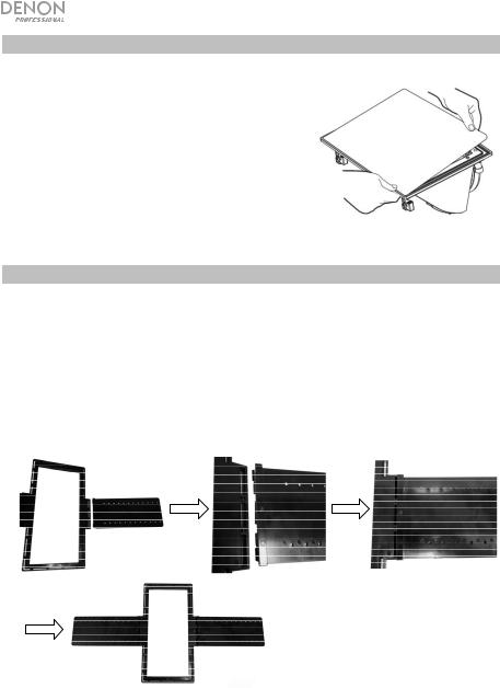
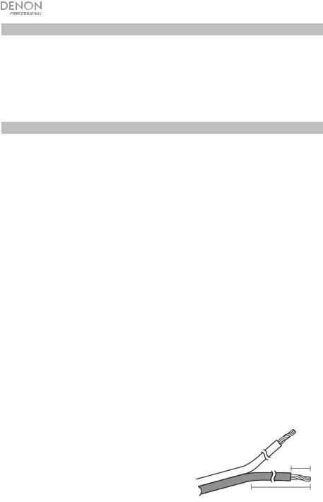
When you are ready to prepare your speaker wires, first separate about 4" (101 mm) of wire, then strip about 1/4" (6 mm) insulation from the end and twist it to prevent stray strands. If you plan to use banana or pin plugs (highly recommended), install the plugs on the wire.
1/4” (6 mm)
4” (101 mm)
3
Painting
The grille and frame can be painted to match your walls or ceiling, making the speaker even less noticeable. Perform the following steps to safely paint without damaging the speaker.
1.Completely remove the grille by lifting the edge to pull it off the speaker body.
2.Remove the felt matte from the back of the grille.
3.Paint the speaker grille. It is best to use spray paint to avoid paint clogging the holes in the grille.
4.Allow the paint to completely dry; then reattach the felt matte on the back of the grille.
5.Before proceeding with the installation, ensure that the holes in the grille are not blocked by paint.
Installing DN-205W in a New Building
The following steps provide detailed instructions for installing the speaker into a new building construction. The speaker can be mounted to a wall or ceiling that is between 3/8" (9.5 mm) and 1-1/4" (31.8 mm) thick, with sufficient depth clearance for the model being installed.
1.Determine where you will be installing the speaker.
2.Connect the speaker mounting panel onto the mounting bracket by taking one of the alignment panels and pressing it under the grooves in the mounting bracket. Repeat this process on the other side. Place the mounting bracket in the desired install location and use 2 screws and 2 washers to attach to the wall/ceiling. Repeat this process on the other side, making sure the holes line up evenly.
Note: Put some insulation (R-14) in the wall/ceiling space before you install the speaker to improve the sound.
3.If you have not already done so, prepare your speaker wire in accordance with the guidelines in the
Speaker Wire Preparation section.
Important! Because the speaker wire will be routed through your walls/ceiling, you must use in-wall rated speaker wire.
4.Route the speaker wire from the back of your amplifier, through the wall or space above the ceiling, to the installation location.
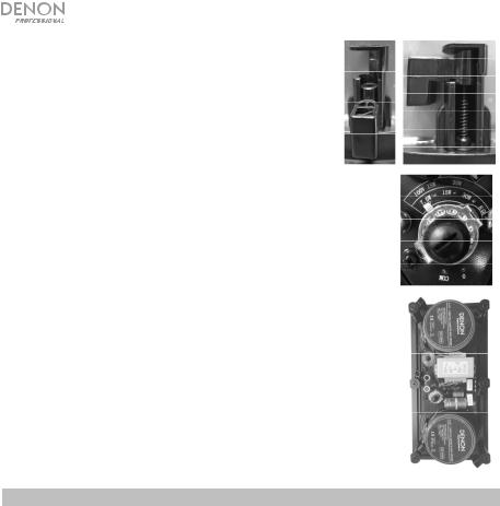
5.Depress the positive/red push terminal on the back of the speaker and insert the bare wire lead or pin plug on the positive lead into the hole on the side of the terminal. Release the terminal.
4
6.Depress the negative/black push terminal and insert the bare wire lead or pin plug on the negative lead into the hole on the side of the terminal; then release the terminal. Gently pull on each lead to ensure that they are securely connected to the terminals.
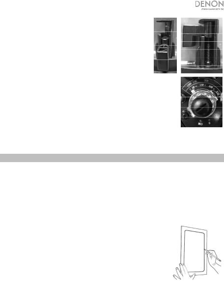
7.Rotate the Tap Selector so that the correct power setting is selected (see side image).
8.Remove the speaker grille, which is held in place with magnets.
9.Ensure that the mounting tabs on the speaker assembly are turned inward.
10.Begin to insert speaker into the speaker mounting bracket. When
the speaker is flush with the wall/ceiling leaving only the black magnetic brim exposed, use a #2 Phillips screwdriver to begin to tighten the 6 attachment screws which are connected to the mounting tabs (see side images). The screws will automatically turn once you begin rotating the screw clockwise. Repeat for all 6 tabs and make sure not to overtighten the screws.
11.Replace the grille onto the speaker body.
12.Ensure that your amplifier is powered off and unplugged from the power source.
13.Connect the amplifier end of the speaker wire to one of the speaker level
outputs on your amplifier, taking care to match the polarity markings on the speaker wire or plugs.
14.Enjoy using the DN-205W!
Installing DN-205W in an Existing Wall/Ceiling
The following steps provide detailed instructions for installing the speaker onto a wall or ceiling that is between 3/8" (9.5 mm) and 1-1/4" (31.8 mm) thick, with sufficient depth clearance for the model being installed. If installing to a drop ceiling, use of a mounting bracket is required.
1.Determine where you will be installing the speaker. Use a stud finder to ensure that there is sufficient space between the desired location and the adjacent studs. Check for framing members that run perpendicular to the main studs. Use a pencil to mark the edges of the adjacent studs.
2.Remove the center portion of the cardboard installation template and position the installation template against the wall or ceiling at the installation location. For wall installations, use a carpenter's level to ensure that the template is level.
3.Use a pencil to mark the cut line. For wall installations, use the level to check the cut lines to ensure they are level.
Note: For installations in high quality, press board drop ceilings, you can cut into the ceiling panels and use the same directions seen below.
4.Drill a small test hole in the middle of the cutout area and take a stiff piece of wire, such as a hanger, and bend it 90°, about 8" (203 mm) from the end. Insert the wire past the bend, then rotate the wire 360° to check for hidden obstructions behind the wall. Push it in to ensure that there is sufficient clearance behind the wall or ceiling.
5.Once you know your installation location is clear, use a drywall or keyhole saw to cut along the cut lines.
6.Remove the wall/ceiling space and check that the speaker fits the hole that you cut.
Note: Put some insulation (R-14) in the wall/ceiling space before you install the speaker to improve the sound.
7.If you have not already done so, prepare your speaker wire in accordance with the guidelines in the
Speaker Wire Preparation section.
Important! Because the speaker wire will be routed through your walls/ceiling, you must use in-wall rated speaker wire.
8.Route the speaker wire from the back of your amplifier, through the wall or space above the ceiling, to the installation location.
9.Remove the speaker grille, which is held in place with magnets.
5
10.Depress the positive/red push terminal on the back of the speaker and insert the bare wire lead or pin plug on the positive lead into the hole on the side of the terminal. Release the terminal.
11.Depress the negative/black push terminal and insert the bare wire lead or pin plug on the negative lead into the hole on the side of the terminal; then release the terminal. Gently pull on each lead to ensure that they are securely connected to the terminals.
12.Rotate the Tap Selector so that the correct power setting is selected (see side image).
13.Ensure that the mounting tabs on the speaker assembly are turned inward.
14.Begin to insert speaker into the cutout hole. When the speaker is flush with the wall/ceiling leaving only the black magnetic brim exposed, use a #2 Phillips screwdriver to begin to tighten the 6 attachment screws which are connected to the mounting tabs (see side images). The screws will automatically turn once you begin rotating the screw clockwise. Repeat for all 6 tabs and make sure not to overtighten the screws.
15.Replace the grille onto the speaker body.
16.Ensure that your amplifier is powered off and unplugged from the power source.
17.Connect the amplifier end of the speaker wire to one of the speaker level outputs on your amplifier, taking care to match the polarity markings on the speaker wire or plugs.
18.Enjoy using the DN-205W!
High-Frequency Roll-Off
DN-205W is equipped with a high-frequency roll-off option, which can be used to attenuate the highfrequency response. If the speaker sounds too "bright", perform the following steps to set the highfrequency roll-off.
1.Pull the edge of the grille to remove it.
2.Adjust the high-frequency roll-off switch to the -3 dB or -6 dB position. The default setting is 0 dB (no attenuation).
3.Replace the grille onto the speaker body.
6
Guía del usuario (Español)
Introducción
Gracias por comprar el DN-205W. Este altavoz para pared/cielorraso es la combinación ideal de calidad de sonido y estilo. El altavoz es prácticamente invisible pero es capaz de llenar la sala con audio de alta fidelidad. Con su rejilla magnética extraíble que se puede pintar, este altavoz bidireccional usa un woofer de fibra de carbono para reproducir graves y tonos medios superiores y un tweeter de domo de seda para reproducir frecuencias altas con suavidad.
Contenido de la caja
DN-205W
Rejilla del altavoz
Plantilla de instalación
Soporte de montaje
Guía del usuario
Manual sobre la seguridad y garantía
Soporte
Para obtener la información más reciente acerca de este producto (documentación, especificaciones técnicas, requisitos de sistema, información de compatibilidad, etc.) y registrarlo, visite denonpro.com.
Para soporte adicional del producto, visite denonpro.com/support.
Advertencias de seguridad
•Este altavoz es para uso en interiores únicamente.
•No exponga el altavoz al agua o la humedad.
•Si opera el altavoz en un ambiente húmedo, asegúrese de que no haya condensación.
•Apague y desenchufe todos los componentes de audio/video antes de conectar los cables. Suministre la energía únicamente después de haber realizado todas las conexiones.
•Use únicamente cables para altavoces con clasificación apta para uso en paredes.
•Al comprobar la presencia de objetos detrás de una pared, no fuerce el cable a través de las obstrucciones.
•No intente instalar el altavoz cerca de tomas de corriente, interruptores de pared o accesorios de iluminación en el cielorraso.
•Verifique todas las conexiones antes de suministrar la energía para asegurarse de que la polaridad del altavoz sea la correcta y que no haya fragmentos de cables sueltos que pudieran crear un cortocircuito entre las conexiones.
•No use el volumen máximo hasta que el altavoz se haya “ablandado” (asentado).
•Si escucha distorsión, baje volumen hasta que ya no pueda oírla.
•No use un volumen excesivo para escuchar el altavoz. Si experimenta dolor, incomodidad o mareos, baje el volumen inmediatamente. La exposición prolongada a un volumen excesivo puede causar daños permanentes en el oído.
•No utilice líquidos de limpieza, solventes u otros productos químicos para limpiar el marco o la rejilla del altavoz.
•No desarme o intente reparar este altavoz.
7
Asentamiento del altavoz
Los altavoces requieren de un periodo de asentamiento antes de que puedan operarse de forma segura a los niveles de volumen máximos. Un asentamiento apropiado asegura de que las partes móviles del altavoz (el cono y la suspensión del cono) puedan flexionarse y ablandarse, perdiendo la rigidez inicial y permitiendo que el altavoz se mueva a lo largo de su rango completo. Tras el periodo de asentamiento, los altavoces emitirán graves más ricos, frecuencias medias más cálidas y suaves, y agudos más limpios.
La mejor manera de asentar un altavoz es reproducir música normal a niveles de volumen moderados. La cantidad de tiempo requerida para asentar un altavoz varía en función del entorno de operación, pero suele estar entre 50 y 80 horas. Demorará un poco más en un ambiente frío o seco y un poco menos en un ambiente cálido húmedo.
Nota: El periodo de asentamiento no necesita ser continuo.
Preparación del cableado del altavoz
Antes de intentar realizar cualquier conexión es mejor considerar la ubicación, reunir todos los materiales necesarios y luego realizar todas las conexiones de una sola vez.
Primero, observe la parte trasera de su amplificador receptor para determinar las opciones que ofrece para realizar conexiones. Los amplificadores y receptores suelen emplear bornes para conexión de 5 vías, terminales accionados por resortes o terminales de empuje para las conexiones del altavoz.
Un borne para conexión de 5 vías acepta cables pelados de altavoz, conectores tipo espada, clavija o banana, mientras que los terminales accionados por resorte o los terminales de empuje aceptan cables pelados o conectores tipo clavija. Consulte la documentación que vino junto con su amplificador o receptor para determinar el tamaño/calibre máximo para el cable del altavoz que aceptan los terminales para altavoz.
El DN-205W viene con terminales de empuje, los cuales pueden aceptar conectores tipo clavija o cables pelados de hasta 14 AWG. Si su amplificador lo soporta, debería usar cable para altavoz de 14 AWG. Se recomienda expresamente el uso de conectores tipo clavija ya que son más fáciles de conectar, no hay riesgo de que haya fragmentos de cable sueltos que pongan las conexiones en cortocircuito, permiten el uso de cables para altavoz de mayor calibre en la mayoría de los casos y resulta mucho más fácil identificar la polaridad a partir de un anillo codificado con colores en un conector que a partir de una marca muy sutil a lo largo de la longitud de un cable.
Dado que los cables del altavoz atravesarán sus paredes/cielorraso, debe usar cable con clasificación para paredes la cual requieren los códigos de seguridad para incendios. Esto asegura que el aislamiento del cable no actuará como un acelerador en caso de incendio.
En lugar de usar cables para altavoz de longitud fija, es mejor obtener un carrete y cortar los cables a la medida necesaria. Esto garantizará que haya una cantidad mínima de cable adicional. Sin embargo, incluso si su amplificador no está en el centro, las longitudes de los cables usados para cada par de altavoces deberían ser las mismas. Esto mantiene la impedancia en cada canal en el mismo nivel, lo cual garantiza que los niveles de volumen, rangos de frecuencia y tonalidades sean idénticas. Cualquier exceso de cable debe plegarse a lo largo tipo zigzag, no enrollarse, para evitar la creación de un inductor/antena que capte señales de radio.
Antes de realizar las conexiones reales, corte cada tramo de cable a la longitud deseada. Tome nota de las marcas en los cables que diferencian a cada conductor. En ocasiones las marcas identifican claramente el lado positivo y lado negativo. Algunas de las marcas o identificadores claros más comunes para positivo y negativo son:
Positivo |
Negativo |
Rojo |
Negro |
Cobre |
Plata |
+ + + |
- - - |
En muchos casos, la marca es una sola raya en el aislamiento de uno de los conectores. En este caso el lado con la raya se suele considerar como el positivo, pero esto realmente no importa siempre que usted mantenga la consistencia y use la raya siempre como el positivo o siempre como el negativo.
Cuando esté listo para preparar los cables de su altavoz, primero separe aproximadamente 101 mm (4 pulg.) de cable y luego pele aproximadamente 6 mm (1/4 pulg.) del aislamiento desde el extremo y retuérzalo para evitar que los filamentos se separen. Si planea utilizar conectores tipo banana o tipo clavija (altamente recomendados), coloque los conectores en el cable.
6 mm (1/4 pulg.)
101 mm (4 pulg.)
8

Pintura
La rejilla y el marco se pueden pintar para que combinen con sus paredes o cielorraso, haciendo que el altavoz pase aún más desapercibido. Lleve a cabo los siguientes pasos para pintar de forma segura sin dañar el altavoz.
1.Retire la rejilla completamente levantando el borde para extraerla del cuerpo del altavoz.
2.Quite el fieltro mate de la parte trasera de la rejilla.
3.Pinte la rejilla del altavoz. Es mejor usar pintura en aerosol para evitar que los grumos de pintura obstruyan los orificios en la rejilla.
4.Permita que la pintura se seque completamente; luego vuelva a colocar el fieltro mate en la parte trasera de la rejilla.
5.Antes de continuar con la instalación, asegúrese de que los orificios en la rejilla no queden obstruidos por la pintura.
Instalación del DN-205W en un edificio nuevo
Los siguientes pasos brindan instrucciones detalladas sobre la instalación del altavoz en un edificio nuevo. El altavoz se puede montar en una pared o cielorraso de entre 9,5 mm (3/8 pulg.) a 31,8 mm (1-1/4 pulg.) de grosor, con suficiente espacio de profundidad para el modelo que se está instalando.
1.Determine el lugar en donde instalará el altavoz.
2.Conecte el panel de montaje del altavoz en el soporte de montaje tomando uno de los paneles de alineamiento y presionándolo por debajo de las canaletas en el soporte de montaje. Repite este proceso del otro lado. Coloque el soporte de montaje en la posición de instalación deseada y utilice dos tornillos y los arandelas para sujetarlo a la pared/cielorraso. Repita este proceso del otro lado, asegurándose de que los orificios se alineen de forma pareja.
Nota: Coloque aislamiento (R-14) en el espacio de la pared/cielorraso antes de instalar el altavoz para mejorar el sonido.
3.Si todavía no lo hizo, prepare los cables de su altavoz siguiendo las directrices de la sección
Preparación del cableado del altavoz.
¡Importante! Dado que los cables del altavoz atravesarán sus paredes/cielorraso, debe usar cable con clasificación para paredes.
4.Encamine el cable del altavoz desde la parte trasera de su amplificador, a través de su pared o espacio encima del cielorraso, hasta el lugar de la instalación.
9
 Loading...