


 Loading...
Dell™ Server Console Switch
User's Guide

Notes, Cautions, and Warnings
NOTE: A NOTE indicates important information that helps you make better use of your computer.
CAUTION: A CAUTION indicates potential damage to hardware or loss of data if instructions are not followed.
WARNING: A WARNING indicates a potential for property damage, personal injury, or death.
____________________
Information in this publication is subject to change without notice. © 2011 Dell Inc. All rights reserved.
Reproduction of these materials in any manner whatsoever without the written permission of Dell Inc. is strictly forbidden.
Trademarks used in this text: Dell, the DELL logo, and PowerEdge are trademarks of Dell Inc.; Avocent is a registered trademark of Avocent Corporation. Microsoft®, Windows®, Windows Server®, MS-DOS®, and Windows Vista® are either trademarks or registered trademarks of Microsoft Corporation in the United States and/or other countries. Red Hat Enterprise Linux® and Enterprise Linux® are registered trademarks of Red Hat, Inc. in the United States and/or other countries.
Other trademarks and trade names may be used in this publication to refer to either the entities claiming the marks and names or their products. Dell Inc. disclaims any proprietary interest in trademarks and trade names other than its own.
590-1068-501A
Model 1081AD/2161AD Server Console Switch July 2011

Contents
Product Overview |
1 |
Features and Benefits |
1 |
Reduce Cable Bulk |
1 |
SIP Intelligent Modules |
1 |
Multiplatform Support |
2 |
User Interfaces |
2 |
Virtual Media and Smart Card-capable Switches |
3 |
IPv4 and IPv6 Capabilities |
3 |
Access the SCS Using a Standard TCP/IP Network |
4 |
Upgradeable |
4 |
Two-tier Expansion |
4 |
Dell Remote Access Key (RAK) |
4 |
KVM Remote Access |
4 |
Avocent Management Software Plug-in |
5 |
Local Video Scaling |
5 |
Encryption |
5 |
Safety Precautions |
7 |
General |
7 |
LAN Related Precautions |
9 |
Installation |
11 |
Getting Started |
11 |
Setting Up Your Network |
12 |
SCS Quick Setup |
13 |
Rack Mounting the Switch |
14 |
Rack Mounting Safety Considerations |
14 |
Contentsxxx | xxx3

Installing the Dell ReadyRails System |
15 |
Installing the Switch |
20 |
Connecting the SCS Hardware |
23 |
Tiering Your Switch Using a SIP |
26 |
Adding a Tiered Switch |
29 |
Adding a Tiered Legacy Switch |
31 |
Adding a Port Expansion Module (Optional) |
33 |
Configuring Your SCS |
35 |
Setting Up the Built-in Web Server |
35 |
Connecting to the OBWI Through a Firewall |
35 |
Verifying Power Status |
37 |
Adjusting Mouse Settings on Target Devices |
37 |
Local OSCAR User Interface |
39 |
Main Dialog Box Functions |
39 |
Viewing and Selecting Ports and Devices |
39 |
Viewing Switch System Status |
41 |
Selecting Devices |
42 |
Soft Switching |
43 |
Navigating the OSCAR Interface |
43 |
Connecting Local Virtual Media |
45 |
Setup Dialog Box Functions |
46 |
Changing the Display Behavior |
47 |
Controlling the Status Flag |
48 |
Setting the Keyboard Country Code |
49 |
Assigning Device Types |
50 |
Assigning Device Names |
50 |
Configuring Network Settings |
51 |
Commands Dialog Box Functions |
52 |
Selecting Devices for Scan Mode |
53 |
Contentsxxx | xxx4

Enabling or Disabling Scan Mode |
54 |
Viewing and Disconnecting User Connections |
54 |
Displaying Version Information and Upgrading Firmware |
55 |
OBWI Operation |
57 |
Using the OBWI |
59 |
Viewing System Information |
61 |
Scan Mode |
63 |
Generating a Certificate |
63 |
Tools - Rebooting and Upgrading |
65 |
Rebooting the SCS |
65 |
Upgrading SCS Firmware |
65 |
Saving and Restoring SCS Configurations and User Databases |
66 |
Property Identity and Location Settings |
68 |
Viewing Version Information |
68 |
Network Settings |
68 |
SNMP Settings |
70 |
Auditing Event Settings |
71 |
Setting Event Destinations |
71 |
Ports SettingsConfiguring a SIP |
72 |
Deleting SIPs |
72 |
Upgrading SIPs |
72 |
Launching a Session |
73 |
General Sessions Settings |
74 |
Local User Account Settings |
75 |
Virtual Media Session Settings |
76 |
Contentsxxx | xxx5

Avocent User Account Settings |
78 |
Override Admin |
78 |
Active Sessions |
79 |
Closing a Session |
79 |
Video Viewer |
81 |
Changing the Toolbar |
84 |
Window Size |
84 |
Adjusting the View |
85 |
Refreshing the Image |
86 |
Video Settings |
86 |
Target Video Settings |
88 |
Automatic Video Adjustment |
89 |
Video Test Pattern |
89 |
Vendor-specific Video Settings |
89 |
Color Settings |
89 |
Contrast and Brightness |
90 |
Noise Settings |
90 |
Mouse Settings |
91 |
Cursor Type |
91 |
Mouse Scaling |
94 |
Mouse Alignment and Synchronization |
94 |
Virtual Media |
95 |
Requirements |
95 |
Sharing and Preemption Considerations |
96 |
Virtual Media Dialog Box |
96 |
Opening a Virtual Media Session |
97 |
Contentsxxx | xxx6

Closing a Virtual Media Session |
100 |
Smart Cards |
101 |
Keyboard Pass-through |
102 |
Macros |
103 |
Saving the View |
103 |
Closing a Session |
103 |
Terminal Operation |
105 |
Network Configuration |
105 |
Other Console Main Menu Options |
106 |
Firmware Management |
107 |
Enable Debug Messages |
107 |
Set/Change Password |
107 |
Restore Factory Defaults |
107 |
Reset Switch |
107 |
Set Web Interface Ports |
107 |
Exit |
107 |
Appendix A: MIB and SNMP Traps |
109 |
Appendix B: Setup Port Pinouts |
113 |
Appendix C: Using Avocent Serial IQ Modules |
115 |
Serial IQ Module Modes |
115 |
Configuring the Serial IQ Module |
115 |
Creating a Serial IQ Module Macro |
118 |
Using History Mode |
119 |
Contentsxxx | xxx7

Serial IQ Module Pinouts |
120 |
Appendix D: Sun Advanced Key Emulation |
121 |
Appendix E: UTP Cabling |
123 |
UTP Copper Cabling |
123 |
Wiring Standards |
123 |
Cabling Installation, Maintenance, and Safety Tips |
124 |
Appendix F: Technical Specifications |
127 |
Appendix G: Technical Support |
131 |
Contentsxxx | xxx8
1
Product Overview
The Dell 1081AD/2161AD Server Console Switch (SCS) is an analog keyboard, video, and mouse (KVM) switch that provides flexible, centralized local access to data center servers. It can also provide centralized remote access to data center servers when used in conjunction with the optional Remote Access Key (RAK).
Features and Benefits
Reduce Cable Bulk
With device densities continually increasing, cable bulk remains a major concern for network administrators. The SCS significantly reduces KVM cable volume in the rack by utilizing the innovative Server Interface Pod (SIP) and single, industry-standard Unshielded Twisted Pair (UTP) cabling. This allows a higher device density while providing greater airflow and cooling capacity.
SIP Intelligent Modules
The SCS supports SIPs that are powered directly from the target device and provide Keep Alive functionality when the SCS is not powered. The SIPs with CAT 5 design dramatically reduce cable clutter while providing optimal resolution and video settings. The built-in memory of SIPs simplifies configuration by assigning and retaining unique device names and Electronic ID (EID) numbers for each attached device.
PS/2 and USB SIPs are available allowing direct KVM connectivity to devices. The USB2+CAC SIP is also available. The SCS is offered with 8 or 16 ARI
Product Overviewxxx | xxx1

ports that are used to connect SIPs to the SCS. Then utilizing the SIPs, you can attach additional switches to expand your SCS system. This flexibility allows you to add capacity as your data center grows.
Multiplatform Support
Dell SIPs are available for use with the SCS to support PS/2, USB, USB2, and USB2+CAC device environments.
Interoperability with Avocent® IQ Module Intelligent Cabling may also be used to connect local devices to the SCS. PS/2, USB, and Sun® module options are available. For more information, please refer to the appropriate Avocent installer/user guide for your product or visit avocent.com/manuals for more information.
User Interfaces
The SCS is equipped with two “point-and-click” interfaces to manage the SCS locally. They are the local user interface (UI), referred to as OSCAR™, and the on-board web interface (OBWI). Using the configuration options provided by these interfaces, you can tailor your SCS to your specific application. The OBWI can also be used to access and control any attached devices, and handle all basic KVM needs remotely.
NOTE: Remote KVM sessions via the OBWI requires the installation of the Dell RAK.
OSCAR Interface
The OSCAR interface, accessed using the local port, features intuitive menus and operation modes to configure your SCS and devices. Devices can be identified by name, EID, or port number.
The OSCAR interface allows you to protect your system with a screen saver password. When the screen saver mode engages, access is prohibited until the appropriate password is entered to reactivate the system. By typing Help in the password dialog, you are directed to Dell Technical Support. Recommended usage for the SCS is in a data center infrastructure protected by a firewall.
2xxx | Product Overviewxxx
OBWI
You can also use the OBWI to manage your SCS. The OBWI is launched directly from the SCS and does not require a software server or any installation. With the addition of the optional Dell RAK installed, you can also establish remote KVM and virtual media sessions to target devices. For more information, see "Dell Remote Access Key (RAK)" on page 4.
Terminal Console Interface
The terminal console interface is accessed through the "10101" setup port. A terminal screen or a PC running terminal emulation software can be used to access these screens.
Virtual Media and Smart Card-capable Switches
The SCS allows you to view, move, or copy data located on local media and smart cards. Smart cards are pocket-sized cards that store and process information including identification and authentication information to enable access to computers, networks, and secure rooms or buildings.
A virtual media or a smart card reader can be connected directly to the USB ports on the SCS. In addition, virtual media or smart card readers may be connected to any remote workstation that is running the remote OBWI, SCS Software, or Avocent management software, and is connected to the SCS using an Ethernet connection.
NOTE: To open a virtual media or smart card session with a target device, you must first connect the target device to an SCS using a USB 2.0 or USB+CAC SIP.
IPv4 and IPv6 Capabilities
The SCS is compatible with systems using either of the currently used Internet Protocol Versions, IPv4 or IPv6. You can change the network settings and choose either IPv4 or IPv6 mode via the terminal console, OSCAR interface, or OBWI.
Product Overviewxxx | xxx3

Access the SCS Using a Standard TCP/IP Network
The device is accessible for configuration via the standard TCP/IP Network. If the optional Dell RAK is installed, you can access all attached systems via Ethernet. See "Dell Remote Access Key (RAK)" on page 4.
NOTE: The client connects to the SCS using an Internet browser.
NOTE: KVM over IP sessions are supported when the Dell RAK is installed.
Upgradeable
Upgrade your SCS and SIPs at any time to ensure you are always running the most current firmware version available. Upgrades can be initiated through the OSCAR interface, OBWI, or the terminal console screens. The SCS can also be configured to perform automatic firmware upgrades of SIPs. For more information, see "Tools - Rebooting and Upgrading" on page 65.
Two-tier Expansion
The SCS allows you to tier one additional SCS, CS, or RCS from each ARI port on the primary SCS. Each tiered SCS is attached in the same manner as any device. This additional tier of units allows you to attach up to 512 servers in one system. See "Tiering Your Switch Using a SIP" on page 26.
Dell Remote Access Key (RAK)
The optional Dell RAK, installed in the USB port, supports the following features.
KVM Remote Access
A single KVM remote user is supported using the RAK. With the RAK, you can manage remote operating system installation, operating system recovery, hard drive recovery or duplication, BIOS updating, and server backup.
4xxx | Product Overviewxxx
Avocent Management Software Plug-in
Avocent management software may be used with the SCS to allow IT administrators to securely and remotely access and monitor target devices on multiple platforms through a single, web-based user interface. A session may be launched to a device from a single point of access. For more information, see the Technical Bulletin for the management software plug-in.
Local Video Scaling
The SCS digitizes a video signal with a maximum pixel resolution of up to 1600 x 1200 or 1680 x 1050 (widescreen), depending on the length of cable separating your SCS and devices.
Encryption
The SCS supports 128-bit SSL(ARCFOUR), AES, DES, and 3DES encryption of keyboard/mouse, video, and virtual media sessions.
Product Overviewxxx | xxx5

Figure 1.1: Example Server Console Switch Configuration
Table 1.1: Descriptions for Figure 1.1
Number Description |
Number Description |
1 |
UTP Connection |
5 |
|
2 |
Local KVM Connection to |
6 |
|
the Server Console Switch |
|||
3 |
Remote IP Connection |
7 |
|
4 |
Server Console Switch |
8 |
|
(2161AD shown) |
|||
|
|
Ethernet
Digital Users (computer with Internet Browser for OBWI or RCS Software and/or Avocent Management Software Server [requires the Dell RAK])
Local Analog Users (OSCAR Interface and/or Local LCD Tray)
Servers/Target Devices
6xxx | Product Overviewxxx

Safety Precautions
This document pertains only to the Dell 1081AD/2161AD Server Console Switch. You should also refer to the following additional safety instructions.
•Dell Safety Sheet
•Dell RTF Regulatory Tech Bulletin
General
Use the following safety guidelines to help ensure your own personal safety and to help protect your system and working environment from potential damage.
CAUTION: The power supplies in your system may produce high voltages and energy hazards, which can cause bodily harm. Only trained service technicians are authorized to remove the covers and access any of the components inside the system. This warning applies to the Dell™ Server Console Switch, Dell™ PowerEdge™ server, and Dell PowerVault™ storage system.
•Observe and follow service markings.
•Do not service any product except as explained in your system documentation.
•Opening or removing covers that are marked with the triangular symbol with a lightning bolt may expose you to electrical shock.
•Components inside these compartments should be serviced only by a trained service technician.
•This product contains no serviceable components. Do not attempt to open.
•If any of the following conditions occur, unplug the product from the electrical outlet and replace the part or contact your trained service provider:
•The power cable, extension cable, or plug is damaged.
•An object has fallen into the product.
Product Overviewxxx | xxx7

•The product has been exposed to water.
•The product has been dropped or damaged.
•The product does not operate correctly when you follow the operating instructions.
•Keep your system away from radiators and heat sources. Also, do not block cooling vents.
•Do not spill food or liquids on your system components, and never operate the product in a wet environment. If the system gets wet, see the appropriate section in your troubleshooting guide or contact your trained service provider.
•Use the product only with approved equipment.
•Allow the product to cool before removing covers or touching internal components.
•Operate the product only from the type of external power source indicated on the electrical ratings label. If you are not sure of the type of power source required, consult your service provider or local power company.
NOTE: To help avoid damaging your system, be sure the voltage selection switch (if provided) on the power supply is set for the voltage that most closely matches the AC power available in your location. Also be sure that your monitor and attached devices are electrically rated to operate.
•Be sure that your monitor and attached devices are electrically rated to operate with the power available in your location.
•Use only power cables provided with this product.
•To help prevent electric shock, plug the system and peripheral power cables into properly grounded electrical outlets. These cables are equipped with three-prong plugs to help ensure proper grounding. Do not use adaptor plugs or remove the grounding prong from a cable.
8xxx | Product Overviewxxx
•Observe extension cable and power strip ratings. Make sure that the total ampere rating of all products plugged into the power strip does not exceed 80 percent of the ampere ratings limit for the power strip.
•To help protect your system from sudden, transient increases and decreases in electrical power, use a surge suppressor, line conditioner, or uninterruptible power supply (UPS).
•Position system cables and power cables carefully. Route cables so that they cannot be stepped on or tripped over. Be sure that nothing rests on any cables.
•Do not modify power cables or plugs. Consult a licensed electrician or your power company for site modifications. Always follow your local/national wiring rules.
LAN Related Precautions
•Do not connect or use during a lightning storm. There may be a risk of electrical shock from lightning.
•Never connect or use in a wet environment.
Product Overviewxxx | xxx9
10xxx | Product Overviewxxx

2
Installation
The SCS uses TCP/IP for communication over Ethernet. For the best system performance, use a dedicated, switched 100BaseT network. You can also use 10BaseT Ethernet.
You may use the terminal software, OSCAR interface, or the OBWI to manage your SCS system. The OBWI manages a single switch and its connections. With the optional Dell RAK, you can also perform KVM and serial switching tasks using the OBWI or Avocent management software. For more information about Avocent management software, visit http://www.avocent.com/dell.
NOTE: The RCS software can be used to manage other switches. For more information, please refer to the appropriate installer/user guide for your product.
NOTE: Ensure that every switch has been upgraded to the most recent version of firmware. For information on upgrading the switch using the OBWI, see "Tools - Rebooting and Upgrading" on page 65.
Getting Started
The following items are supplied with the SCS. Before installing your SCS, locate the necessary items for proper installation.
•Server Console Switch
•Power Cord
•0U Mounting Bracket Kit
•1U Mounting Bracket Kit (two additional rails are pre-mounted to the SCS assembly)
•Cable and Adaptors for the 10101 Console Setup Port
Installationxxx | xxx11

•User Documentation CD
•Server Console Switch Quick Installation Guide
•Dell Rack Mounting Quick Installation Guide
•Dell Safety Sheet
•Dell RTF Regulatory Technical Bulletin Additional items needed:
•One Dell SIP or Avocent IQ module per attached device
•One CAT 5 Patch Cable (up to 30 meters) per attached device Optional Items:
•Dell Remote Access Key (RAK)
•Port Expansion Module (PEM)
NOTE: You cannot open a virtual media session or a CAC session if the device is connected via a PEM.
Setting Up Your Network
The SCS uses IP addresses to uniquely identify the SCS and attached devices. The SCS supports both Dynamic Host Configuration Protocol (DHCP) and static IP addressing. Make sure that an IP address is reserved for each SCS and that each IP address remains static while the SCS is connected to the network.
Keyboards
A USB keyboard and mouse can be connected to the analog ports of the SCS.
NOTE: The SCS also supports the use of multiple keyboards and multiple mice on the analog port. The use of more than one input device simultaneously, however, may produce unpredictable results.
12xxx | Installationxxx
SCS Quick Setup
The following is a quick setup list. For detailed rack mounting and installation instructions, see "Rack Mounting the Switch" on page 14.
1Unpack the SCS and verify that all components are present and in good condition.
2Install the SCS hardware and connect a SIP or Avocent IQ module to each target device or tiered SCS. Connect each SIP or Avocent IQ module to the SCS with CAT 5 cabling and connect the keyboard, monitor, and mouse connectors to the analog ports of the SCS.
3Connect the local port peripherals to the appropriate ports on the back panel of the SCS and set up the network configuration. The IP address can be set here or from the RCS software. Dell recommends using a static IP address.
4For the local port connection, input all device names using the OSCAR interface or the OBWI.
5Adjust mouse acceleration on each device to Slow or None.
To set up the RCS software (see the Remote Console Switch Software User's Guide):
1Install the RCS software on each client workstation.
2From one client workstation, launch the RCS software.
3If you have installed the RAK, click the New Server Console Switch task button to add the new switch to the RCS software database. If you configured the IP address as described above, select Yes, the product already has an IP address; otherwise select No, the product does not have an IP address.
The RCS software will find the switch and all SIPs connected to it and display the names in the Explorer.
Installationxxx | xxx13

NOTE: Using RCS software you can add and manage the Dell SCS, Dell RCS, and some Avocent switches.
4Set properties and group devices as desired into locations, sites, or folders through the Explorer.
5Create user accounts through the OBWI. For more information, see "Local User Account Settings" on page 75.
6If the local user adds, deletes, or renames any SIPs after you have loaded this file, you can resynchronize your local SCS by selecting the SCS and clicking Resync. To control a connected device, select it in the Explorer and click the Connect Video task button to launch a device session in the Viewer.
7Select View - Scaling to adjust the resolution and select View - Color of the device video quality in the Viewer.
Rack Mounting the Switch
You may either place the switch on the rack shelf or mount the switch directly into a 19" wide, EIA-310-E compliant rack (four-post, two-post, or threaded methods). The Dell ReadyRails™ system is provided for 1U front-rack, 1U rearrack, and two-post installations. The ReadyRails system includes two separately packaged rail assemblies and two rails that are shipped attached to the sides of the switch. In addition, one mounting bracket is provided for 0U configurations, and one blanking panel is provided for rear-rack installations.
WARNING: This is a condensed reference. Read the safety instructions in your Safety, Environmental, and Regulatory Information booklet before you begin.
NOTE: The illustrations in this document are not intended to represent a specific switch.
Rack Mounting Safety Considerations
•Rack Loading: Overloading or uneven loading of racks may result in shelf or rack failure, causing damage to equipment and possible personal injury. Stabilize racks in a permanent location before loading begins. Mount
14xxx | Installationxxx
components beginning at the bottom of the rack, then work to the top. Do not exceed your rack load rating.
•Power considerations: Connect only to the power source specified on the unit. When multiple electrical components are installed in a rack, ensure that the total component power ratings do not exceed circuit capabilities. Overloaded power sources and extension cords present fire and shock hazards.
•Elevated ambient temperature: If installed in a closed rack assembly, the operating temperature of the rack environment may be greater than room ambient. Use care not to exceed the 50°C maximum ambient temperature of the switch.
•Reduced air flow: Install the equipment in the rack so that the amount of airflow required for safe operation of the equipment is not compromised.
•Reliable earthing: Maintain reliable earthing of rack-mounted equipment. Pay particular attention to supply connections other than direct connections to the branch circuit (for example, use of power strips).
•Product should not be mounted with the rear panel facing in the downward position.
Installing the Dell ReadyRails System
The ReadyRails system is provided to easily configure your rack for installation of your switch. The ReadyRails system can be installed using the 1U tool-less method or one of three possible 1U tooled methods (two-post flush mount, twopost center mount, or four-post threaded).
1U Tool-less Configuration (Four-post Square Hole or Unthreaded Round Hole)
1With the ReadyRails flange ears facing outward, place one rail between the left and right vertical posts. Align and seat the rear flange rail pegs in the rear vertical post flange. In Figure 2.1, item 1 and its extractions illustrate how the pegs appear in both the square and unthreaded round holes.
Installationxxx | xxx15

Figure 2.1: 1U Tool-less Configuration
2Align and seat the front flange pegs in the holes on the front side of the vertical post (item 2).
3Repeat this procedure for the second rail.
4To remove each rail, pull on the latch release button on each flange ear (item 3) and unseat each rail.
Two-Post Flush-Mount Configuration
1For this configuration, the castings must be removed from the front side of each ReadyRails assembly (Figure 2.2, item 1). Use a Torx™ driver to remove the two screws from each front flange ear (on the switch side of the rail) and remove each casting. Retain castings for future rack requirements. It is not necessary to remove the rear flange castings.
16xxx | Installationxxx
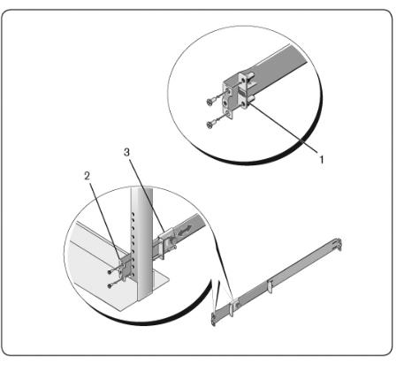
Figure 2.2: Two-post Flush-mount Configuration
2Attach one rail to the front post flange with two user-supplied screws (item 2).
3Slide the plunger bracket forward against the vertical post and secure the plunger bracket to the post flange with two user-supplied screws (item 3).
4Repeat this procedure for the second rail.
Installationxxx | xxx17
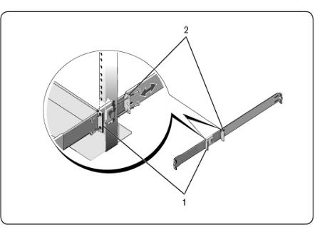
Two-post Center-mount Configuration
1Slide the plunger bracket rearward until it clicks into place and secure the bracket to the front post flange with two user-supplied screws (Figure 2.3, item 1).
Figure 2.3: Two-post Center-mount Configuration
2Slide the back bracket towards the post and secure it to the post flange with two user-supplied screws (item 2).
3Repeat this procedure for the second rail.
Four-post Threaded Configuration
1For this configuration, the flange ear castings must be removed from each end of the ReadyRails assemblies. Use a Torx™ driver to remove the two
18xxx | Installationxxx
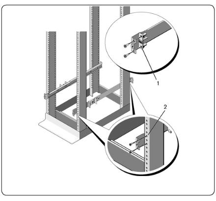
screws from each flange ear and remove each casting (Figure 2.4, item 1). Retain castings for future rack requirements.
2For each rail, attach the front and rear flanges to the post flanges with two user-supplied screws at each end (item 2).
Figure 2.4: Four-post Threaded Configuration
Installationxxx | xxx19
Installing the Switch
The switch may be mounted in the 1U rear-rack, 1U front-rack, 1U two-post (flush and center), and 0U configurations. The following are examples of 1U rearrack, 1U front-rack, and 0U configurations. For 1U two-post (flush and center) configurations, you can slide the switch into the rails in the same manner as the four-post configurations.
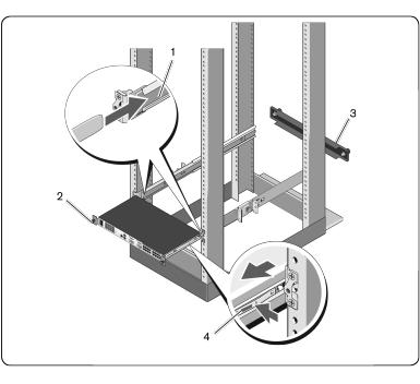
1U Rear-rack Installation
1Insert the ends of the rails that are attached to the switch into the ReadyRails assembly and push the switch into the rack (Figure 2.5, item 1).
Figure 2.5: 1U Rear-rack Installation
2 Secure each switch rail with the thumbscrew (item 2).
20xxx | Installationxxx
3(Optional) Assemble the blanking panel to the rails on the front side of the rack and tighten the thumbscrews (item 3).
To remove the switch from the rack:
1Unscrew the thumbscrews and pull the switch assembly out of the rack until the travel stops are reached. The travel stop position is intended to provide the opportunity to reposition the rail grip; it is not intended for service.
2Locate the blue tabs on the sides of the switch rails (item 4).
3Push the tabs inward and continue pulling the assembly until the switch rails are clear of the ReadyRails assemblies.
1U Front-rack Installation
Before installation, the rails that are attached to the switch must be reconfigured.
1On each switch rail, lift the tab under the front standoff and slide the rail forward as you lift the rail from the switch (Figure 2.6, item 1).
Installationxxx | xxx21
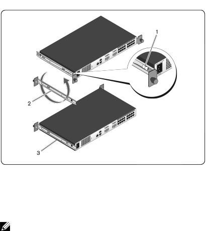
Figure 2.6: Rotating the Switch Rails
2Rotate each rail 180° (item 2) and then reassemble each rail to the switch (item 3).
3Refer to the 1U rear-rack instructions to insert and remove the switch assembly from the ReadyRails system.
NOTE: No blanking panel is required for this configuration.
0U Installation
1Align and assemble the 0U mounting bracket to the switch rails (Figure 2.7, item 1). Tighten the thumbscrews (item 2).
2Insert the mounting bracket hooks into the rack holes and push down until the blue button pops out and locks the bracket into place.
22xxx | Installationxxx
Loading...