


Dell™ Latitude™ E6400 and E6400 ATG and
Mobile Workstation Precision™ M2400 Service Manual
Troubleshooting |
LED Cover |
Working on Your Computer |
Keyboard |
Base Assembly |
Modem |
Hinge Covers |
Right Speaker Grill/Fingerprint Reader Assembly |
Hard Drive |
Palm Rest Assembly |
WLAN/WiMax Card |
Card Cage |
WWAN Card |
1394 Card |
WPAN (UWB/BT) Card |
RJ-11 Modem Connector |
FCM |
System Board Assembly |
Fan |
I/O Card |
Processor Heatsink Assembly |
DC Power Cable |
Processor Module |
Battery Latch Assembly |
Memory |
Display Assembly |
Coin-Cell Battery |
Flashing the BIOS |
Modular Drive |
|
|
|
Notes, Notices, and Cautions
NOTE: A NOTE indicates important information that helps you make better use of your computer.
NOTICE: A NOTICE indicates either potential damage to hardware or loss of data and tells you how to avoid the problem.
CAUTION: A CAUTION indicates potential for property damage, personal injury, or death.
If you purchased a DELL™ n Series computer, any references in this document to Microsoft® Windows® operating systems are not applicable.
Information in this document is subject to change without notice.
© 2008 Dell Inc. All rights reserved.
Reproduction of these materials in any manner whatsoever without the written permission of Dell Inc. is strictly forbidden.
Trademarks used in this text: Dell, Latitude, and the DELL logo are trademarks of Dell Inc.; Bluetooth is a registered trademark owned by Bluetooth SIG, Inc., and is used by Dell under license; Intel is a registered trademark of Intel Corporation in the U.S. and other countries; Microsoft, Windows, Windows Vista, and the Windows Vista start button logo are either trademarks or registered trademarks of Microsoft Corporation in the United States and/or other countries.
Other trademarks and trade names may be used in this document to refer to either the entities claiming the marks and names or their products. Dell Inc. disclaims any proprietary interest in trademarks and trade names other than its own.
Model PP27L
July 2008 |
Rev. A00 |
Back to Contents Page
1394 Card
Dell™ Latitude™ E6400 and E6400 ATG and
Mobile Workstation Precision™ M2400 Service Manual
Removing the 1394 Card
Replacing the 1394 Card
Removing the 1394 Card
CAUTION: Before you begin the following procedure, follow the safety instructions that shipped with your computer.
1.Follow the instructions in Before Working on Your Computer.
2.Remove the bottom of the base assembly (see Removing the Bottom of the Base Assembly).
3.Remove the modular drive (see Removing the Modular Drive).
4.Remove the hinge covers (see Removing the Hinge Covers).
5.Remove the heatsink assembly (see Removing the Processor Heatsink Assembly).
6.Remove the display assembly (see Removing the Display Assembly (E6400 and M2400) or Removing the Display Assembly (E6400 ATG)).
7.Remove the LED cover (see Removing the LED Cover).
8.Remove the keyboard (see Removing the Keyboard).
9.Remove the right speaker grill (see Removing the Right Speaker Grill/Fingerprint Reader Assembly).
10.Remove the palm rest assembly (Removing the Palm Rest Assembly).
11.Remove the card cage (see Removing the Card Cage).
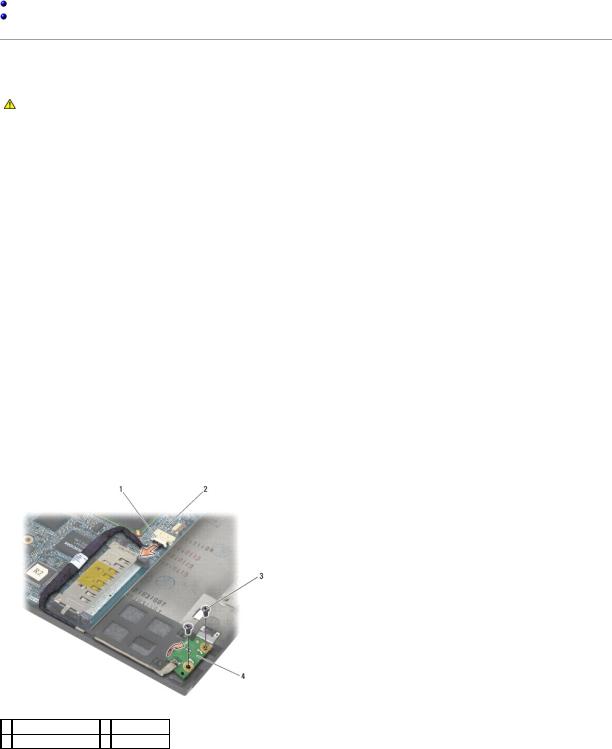
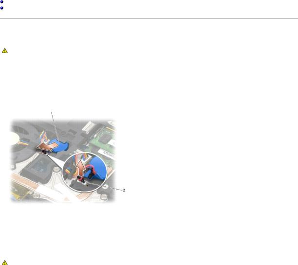
12.Disconnect the 1394 cable from the system board, and unroute the cable.
13.Remove the two M2 x 3 screws.
14.Lift the 1394 card up at an angle and remove it.
1 1394 cable connector 2 system board
3 M2 x 3 screws (2) |
4 1394 card |
|
|

Replacing the 1394 Card
CAUTION: Before you begin the following procedure, follow the safety instructions that shipped with your computer.
1.Insert the 1394 card at a 45-degree angle to fit the connector into the base assembly. Use the alignment pins to seat into position.
2.Replace the two M2 x 3 screws.
3.Route and connect the 1394 cable to the system board.
4.Replace the card cage (see Replacing the Card Cage).
5.Replace the palm rest assembly (Replacing the Palm Rest Assembly).
6.Replace the right speaker grill (see Replacing the Right Speaker Grill/Fingerprint Reader Assembly).
7.Replace the keyboard (see Replacing the Keyboard).
8.Replace the LED cover (see Replacing the LED Cover).
9.Replace the display assembly (see Replacing the Display Assembly (E6400 and M2400) or Replacing the Display Assembly (E6400 ATG)).
10.Replace the heatsink assembly (see Replacing the Processor Heatsink Assembly).
11.Replace the hinge covers (see Replacing the Hinge Covers).
12.Replace the modular drive (see Replacing the Modular Drive).
13.Replace the bottom of the base assembly (see Replacing the Bottom of the Base Assembly).
14.Follow the procedures in After Working on Your Computer.
Back to Contents Page
Back to Contents Page
Base Assembly
Dell™ Latitude™ E6400 and E6400 ATG and
Mobile Workstation Precision™ M2400 Service Manual
Removing the Bottom of the Base Assembly
Replacing the Bottom of the Base Assembly
Removing the Base Assembly
Replacing the Base Assembly
CAUTION: Before you begin any of the procedures in this section, follow the safety instructions that shipped with your computer.
Removing the Bottom of the Base Assembly
1.Follow the procedures in Before Working on Your Computer.
2.Close the display and turn the computer upside down.
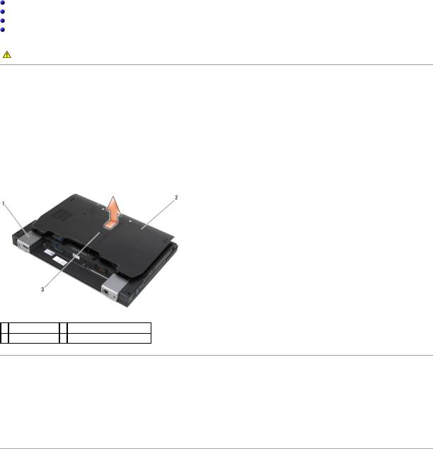
3.Loosen the captive screw.
4.Slide the bottom of the base assembly away from the hinge covers, and lift to remove the bottom of the base assembly.
1 hinges covers (2) 2 bottom of the base assembly
3 captive screw
Replacing the Bottom of the Base Assembly
1.Slide the bottom of the base assembly into place.
2.Tighten the captive screw.
3.Follow the procedures in After Working on Your Computer.
Removing the Base Assembly
1.Follow the procedures in Before Working on Your Computer.
2.Remove the bottom of the base assembly (see Removing the Bottom of the Base Assembly).
3.Remove the card in the WWAN/FCM card slot, if present (see Removing a WWAN Card or Removing an FCM from the WWAN/FCM Slot).
4.Remove the card from the WLAN/WiMax card slot, if present (see Removing the WLAN/WiMax Card).

5.Remove the hinge covers (see Removing the Hinge Covers).
6.Remove the card from the WPAN/UWB/FCM card slot, if present (see Removing a WPAN (UWB/BT) Card or Removing an FCM from the WPAN/UWB/FCM Slot).
7.Remove the heatsink assembly (see Removing the Processor Heatsink Assembly).
8.Remove the hard drive (see Removing the Hard Drive).
9.Remove the modular drive (see Removing the Modular Drive).
10.Remove the display assembly (see Removing the Display Assembly (E6400 and M2400) or Removing the Display Assembly (E6400 ATG)).
11.Remove the LED cover (see Removing the LED Cover).
12.Remove the keyboard (see Removing the Keyboard).
13.Remove the right speaker grill (see Removing the Right Speaker Grill/Fingerprint Reader Assembly).
14.Remove the palm rest assembly (see Removing the Palm Rest Assembly).
15.Remove the card cage (see Removing the Card Cage).
16.Remove the coin-cell battery (see Removing the Coin-Cell Battery).
17.Remove the system board (see Removing the System Board Assembly).
18.Remove the modem (see Removing the Modem).
19.Remove the RJ-11 modem connector (see Removing the RJ-11 Modem Connector).
20.Remove the I/O card (see Removing the I/O Card).
Replacing the Base Assembly
1.Replace the I/O card (see Replacing the I/O Card).
2.Replace the RJ-11 modem connector (see Replacing the RJ-11 Modem Connector).
3.Replace the modem (see Replacing the Modem).
4.Replace the system board (see Replacing the System Board Assembly).
5.Replace the coin-cell battery (see Replacing the Coin-Cell Battery).
6.Replace the card cage (see Replacing the Card Cage).
7.Replace the palm rest assembly (see Replacing the Palm Rest Assembly).
8.Replace the right speaker grill (see Replacing the Right Speaker Grill/Fingerprint Reader Assembly).
9.Replace the keyboard (see Replacing the Keyboard).
10.Replace the LED cover (see Replacing the LED Cover).
11.Replace the display assembly (see Replacing the Display Assembly (E6400 and M2400) or Replacing the Display Assembly (E6400 ATG)).
12.Replace the modular drive (see Replacing the Modular Drive).
13.Replace the hard drive (see Replacing the Hard Drive).
14.Replace the heatsink assembly (see Replacing the Processor Heatsink Assembly).
15.Replace the card in the WPAN/UWB/FCM card slot, if applicable (see Replacing a WPAN (UWB/BT) Card or Replacing an FCM).

16.Replace the hinge covers (see Replacing the Hinge Covers).
17.Replace the card from the WLAN/WiMax card slot, if applicable (see Replacing the WLAN/WiMax Card).
18.Replace the card from the WWAN/FCM card slot, if applicable (see Replacing a WWAN Card or Replacing an FCM).
19.Replace the bottom of the base assembly (see Replacing the Bottom of the Base Assembly).
20.Follow the procedures in After Working on Your Computer.
NOTE: If you use a BIOS update program disc to flash the BIOS, press <F12> before inserting the disc in order to set the computer to boot from the disc for one time only. Otherwise, you must enter the system setup program to change the default boot order.
21.Flash update the BIOS (see Flashing the BIOS for more information).
22.Enter the system setup program to update the BIOS on the new system board with the computer Service Tag. For information on the system setup program, see the Dell™ Technology Guide on your computer or at support.dell.com.
Back to Contents Page

Back to Contents Page
Battery Latch Assembly
Dell™ Latitude™ E6400 and E6400 ATG and
Mobile Workstation Precision™ M2400 Service Manual
Removing a Battery Latch Assembly
Replacing the Battery Latch Assembly
There are two battery latches, a left and a right, and each latch uses a unique latch assembly. The spring, screw, and release buttons are the same for the left and right battery latches.
The removing and replacing procedures are primarily the same for the right and the left battery latch. The differences are noted for the instructions that are different for the right and left battery latches.
Removing a Battery Latch Assembly
CAUTION: Before you begin the following procedure, follow the safety instructions that shipped with your computer.
1.Follow the instructions in Before Working on Your Computer.
2.Remove the bottom of the base assembly (see Removing the Bottom of the Base Assembly).
3.Remove the hard drive (see Removing the Hard Drive).
4.Remove the modular drive (see Removing the Modular Drive).
5.Remove the hinge covers (see Removing the Hinge Covers).
6.Remove the heatsink assembly (see Removing the Processor Heatsink Assembly).
7.Remove the display assembly (see Removing the Display Assembly (E6400 and M2400) or Removing the Display Assembly (E6400 ATG)).
8.Remove the LED cover (see Removing the LED Cover).
9.Remove the keyboard (see Removing the Keyboard).
10.Remove the right speaker grill (see Removing the Right Speaker Grill/Fingerprint Reader Assembly).
11.Remove the palm rest assembly (see Removing the Palm Rest Assembly).
12.Remove the card cage (see Removing the Card Cage).
13.Remove the system board (see Removing the System Board Assembly). Do not remove the wireless mini-cards, memory modules, or processor from the system board.
14.Remove the modem (see Removing the Modem).
15.Remove the RJ-11 modem connector (see Removing the RJ-11 Modem Connector).
16.Remove the I/O card (see Removing the I/O Card).
17.Remove the M2 x 3-mm screw from the alignment bracket, and remove the battery latch assembly.
NOTICE: The spring is not secured to the alignment bracket and can be easily misplaced. When removing the battery latch assembly, place the spring in a secure location until the assembly is ready to be reinstalled.
18. Remove the spring from the alignment bracket and set it aside until the assembly is ready to be reinstalled.
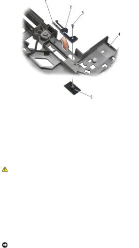
1 |
spring |
2 |
alignment bracket |
|
3 |
M2 x 3-mm screws (2) |
4 |
battery release button |
|
|
|
|
|
|
5 |
base assembly |
|
|
|
|
|
|
|
|
|
|
|
|
|
Replacing the Battery Latch Assembly
CAUTION: Before you begin the following procedure, follow the safety instructions that shipped with your computer.
1.Place the spring on the alignment bracket.
2.Place the battery release button underneath the base assembly.
For the right battery latch assembly, slide the alignment bracket to the left to align the button with the hole in the alignment bracket.
For the left battery latch assembly, slide the alignment bracket to the right to align the button with the hole in the alignment bracket.
3.Replace the M2 x 3-mm screw.
NOTICE: The battery release button is keyed to ensure proper alignment. If you feel resistance, check the alignment of the release button.
4.Replace the I/O card (see Replacing the Battery Latch Assembly).
5.Replace the RJ-11 modem connector (see Replacing the RJ-11 Modem Connector).
6.Replace the modem (see Replacing the Modem).
7.Replace the system board (see Replacing the System Board Assembly).
8.Replace the card cage (see Replacing the Card Cage).
9.Replace the palm rest assembly (see Replacing the Palm Rest Assembly).
10.Replace the right speaker grill (see Replacing the Right Speaker Grill/Fingerprint Reader Assembly).
11.Replace the keyboard (see Replacing the Keyboard).
12.Replace the LED cover (see Replacing the LED Cover).
13.Replace the display assembly (see Replacing the Display Assembly (E6400 and M2400) or Replacing the Display Assembly (E6400 ATG)).
14.Replace the heatsink assembly (see Replacing the Processor Heatsink Assembly).
15.Replace the hinge covers (see Replacing the Hinge Covers).
16.Replace the modular drive (see Replacing the Modular Drive).

17.Replace the hard drive (see Replacing the Hard Drive).
18.Replace the bottom of the base assembly (see Replacing the Bottom of the Base Assembly).
19.Follow the procedures in After Working on Your Computer.
Back to Contents Page

Back to Contents Page
Working on Your Computer
Dell™ Latitude™ E6400 and E6400 ATG and
Mobile Workstation Precision™ M2400 Service Manual
Recommended Tools
Before Working on Your Computer
After Working on Your Computer
This document provides procedures for removing and installing the components in your computer. Unless otherwise noted, each procedure assumes that:
•You have performed the steps in Before Working on Your Computer.
•You have read the safety information that shipped with your computer.
NOTE: The color of your system and certain system components may appear differently than shown in this document.
Recommended Tools
The procedures in this document may require the following tools:
•Small flat-blade screwdriver
•Phillips screwdriver
•Small plastic scribe
•Flash BIOS update (see the Dell Support website at support.dell.com)
Before Working on Your Computer
Use the following safety guidelines to help protect your computer from potential damage and to help ensure your own personal safety.
CAUTION: Before you begin any of the procedures in this section, follow the safety instructions that shipped with your computer.
NOTICE: Only a certified service technician should perform repairs on your computer. Damage due to servicing that is not authorized by Dell is not covered by your warranty.
NOTICE: To avoid electrostatic discharge, ground yourself by using a wrist grounding strap or by periodically touching an unpainted metal surface, such as a connector on the back of the computer.
NOTICE: Handle components and cards with care. Do not touch the components or contacts on a card. Hold a card by its edges or by its metal mounting bracket. Hold a component such as a processor by its edges, not by its pins.
NOTICE: When disconnecting a cable, pull on the cable's connector or on its strain-relief loop, not on the cable itself. For cable connectors with locking tabs, press inward on the locking tabs to release the connector. When connecting a cable, ensure that the connectors are correctly oriented and aligned to avoid damage to the connector and/or the connector's pins.
1.Ensure that the work surface is flat and clean to prevent the computer cover from being scratched.
2.Shut down your computer.
•In Windows XP, click Start® Shutdown® Shutdown.
•In Windows Vista, click Start  , click the arrow
  icon, and then click Shut Down to turn off your computer.
NOTE: Ensure that the computer is off and not in a power management mode. If you cannot shut down the computer using the operating system, press and hold the power button for 4 seconds.
3. Disconnect your computer and all attached devices from their electrical outlets.
NOTICE: To disconnect a network cable, first unplug the cable from your computer, and then unplug it from the network wall jack.
4. Disconnect any telephone or network cables from the computer.
NOTICE: To help prevent damage to the system board, you must remove the battery from the battery bay before you service the computer.
5.Turn the computer upside down.
6.Slide the battery release latches toward each other to lock them in an open position.
7. Slide the battery out of the battery bay.
 1
1  battery
  2
2  battery release latches (2)
8. Disconnect any external devices and remove any installed cards before working on your computer:
•To remove any installed cards, such as an ExpressCard, see the Dell™ Technology Guide on your computer or at support.dell.com.
•To undock from a docking station, see the E-Port User's Guide or the E-Port Plus User's Guide on support.dell.com.
•To remove a battery slice, see the documentation that shipped with your battery slice or on support.dell.com.
•To remove a cool slice, see the documentation that shipped with your cool slice or on support.dell.com.
•To remove a port cover from the E6400 ATG, lift up and ease the port cover away from the connectors along the back of the computer.
 1
1  bottom of computer
  2
2  port cover
9. Turn the computer topside up, open the display, and press the power button to ground the system board.
After Working on Your Computer
After you have completed the replacement procedures, ensure you connect the external devices, cards, cables, etc. before turning on your computer.
NOTE: To avoid damage to the computer, use only the battery designed for this particular Dell computer. Do not use batteries designed for other Dell computers.
1.Connect any external devices, such as a port replicator, battery slice, or cool slice, and replace any cards, such as an ExpressCard.
2.To replace a port cover from the E6400 ATG, fit the port cover into the connectors on the back of the computer.
3.Connect any telephone or network cables to your computer.

4.Replace the battery. Slide the battery into the battery bay until it clicks into place.
5.Connect your computer and all attached devices to their electrical outlets.
6.Turn on your computer.
Back to Contents Page

Back to Contents Page
Flashing the BIOS
Dell™ Latitude™ E6400 and E6400 ATG and
Mobile Workstation Precision™ M2400 Service Manual
Flashing the BIOS From a CD
Flashing the BIOS From the Hard Drive
If a BIOS-update program CD is provided with a new system board, flash the BIOS from the CD. If you do not have a BIOS-update program CD, flash the BIOS from the hard drive.
Flashing the BIOS From a CD
NOTICE: Plug the AC adapter into a known good power source to prevent a loss of power. Failure to do so may cause system damage.
1.Ensure that the AC adapter is plugged in and that the main battery is installed properly.
2.Press <F12> before inserting the BIOS-update program CD so that you can set up the computer to boot from a CD for one time only. Otherwise, you must enter the system setup program to change the default boot order.
3.Insert the BIOS-update program CD, and turn on the computer.
NOTICE: Do not interrupt this process once it begins. Doing so may cause system damage.
Follow the instructions that appear on the screen. The computer continues to boot and updates the new BIOS. When the flash update is complete, the computer will automatically reboot.
4. Remove the flash BIOS update program CD from the drive.
Flashing the BIOS From the Hard Drive
NOTICE: Plug the AC adapter into a known good power source to prevent a loss of power. Failure to do so may cause system damage.
1.Ensure that the AC adapter is plugged in, the main battery is properly installed, and a network cable is attached.
2.Turn on the computer.
3.Locate the latest BIOS update file for your computer at support.dell.com.
4.Click Download Now to download the file.
5.If the Export Compliance Disclaimer window appears, click Yes, I Accept this Agreement.
The File Download window appears.
6.Click Save this program to disk, and then click OK.
The Save In window appears.
7.Click the down arrow to view the Save In menu, select Desktop, and then click Save.
The file downloads to your desktop.
8.Click Close if the Download Complete window appears.
The file icon appears on your desktop and is titled the same as the downloaded BIOS update file.
9.Double-click the file icon on the desktop and follow the instructions on the screen.
Back to Contents Page

Back to Contents Page
Card Cage
Dell™ Latitude™ E6400 and E6400 ATG and
Mobile Workstation Precision™ M2400 Service Manual
Removing the Card Cage
Replacing the Card Cage
Removing the Card Cage
CAUTION: Before you begin any of the procedures in this section, follow the safety instructions that shipped with your computer.
1.Follow the procedures in Before Working on Your Computer.
2.Remove the bottom of the base assembly (see Removing the Bottom of the Base Assembly).
3.Remove the modular drive (see Removing the Modular Drive).
4.Remove the hinge covers (see Removing the Hinge Covers).
5.Remove the heatsink assembly (see Removing the Processor Heatsink Assembly).
6.Remove the display assembly (see Removing the Display Assembly (E6400 and M2400) or Removing the Display Assembly (E6400 ATG)).
7.Remove the LED cover (see Removing the LED Cover).
8.Remove the keyboard (see Removing the Keyboard).
9.Remove the right speaker grill (see Removing the Right Speaker Grill/Fingerprint Reader Assembly).
10.Remove the palm rest assembly (Removing the Palm Rest Assembly).
11.If a card is in the card cage, remove the card.
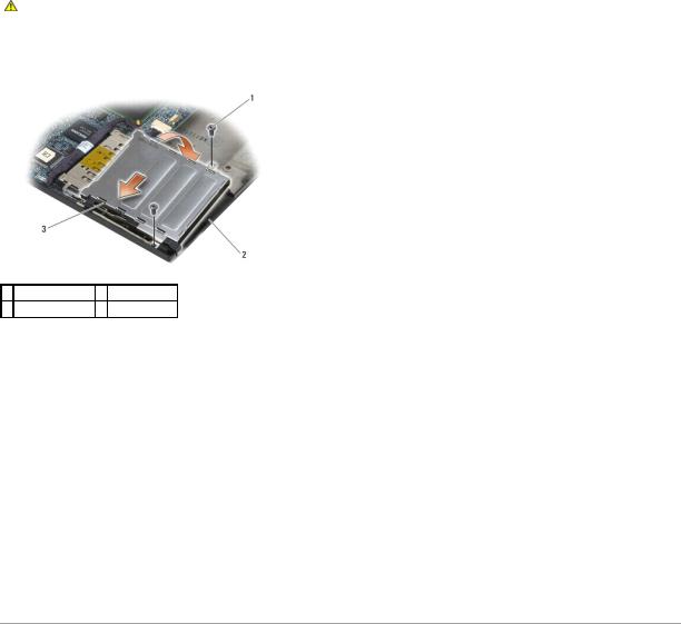
12.Remove the two M2 x 3 screws.
13.Press down on the connector-end of the card cage, then grasp each side of the card cage and push it towards the back of the laptop.
14.Pivot the card cage up to a 45-degree angle, then lift it up from the connector and laptop.
1 M2 x 3 screws (2) 2 card cage
3 connector
Replacing the Card Cage
CAUTION: Before you begin any of the procedures in this section, follow the safety instructions that shipped with your computer.
1.Holding the card cage at a 45-degree angle, attach the front of the card cage to the base assembly, then lower the card cage into place.
2.Replace the two M2 x 3 screws.
1 M2 x 3 screws (2) 2 base assembly
3front of card cage
3.Replace the palm rest assembly (Replacing the Palm Rest Assembly).
4.Replace the right speaker grill (see Replacing the Right Speaker Grill/Fingerprint Reader Assembly).
5.Replace the keyboard (see Replacing the Keyboard).
6.Replace the LED cover (see Replacing the LED Cover).
7.Replace the display assembly (see Replacing the Display Assembly (E6400 and M2400) or Replacing the Display Assembly (E6400 ATG)).
8.Replace the heatsink assembly (see Replacing the Processor Heatsink Assembly).
9.Replace the hinge covers (see Replacing the Hinge Covers).
10.Replace the modular drive (see Replacing the Modular Drive).
11.Replace the bottom of the base assembly (see Replacing the Bottom of the Base Assembly).
12.Follow the procedures in After Working on Your Computer.
Back to Contents Page
Back to Contents Page
Coin-Cell Battery
Dell™ Latitude™ E6400 and E6400 ATG and
Mobile Workstation Precision™ M2400 Service Manual
Removing the Coin-Cell Battery
Replacing the Coin-Cell Battery
Removing the Coin-Cell Battery
CAUTION: Before you begin any of the procedures in this section, follow the safety instructions that shipped with your computer.
1.Follow the procedures in Before Working on Your Computer.
2.Remove the bottom of the base assembly (see Removing the Bottom of the Base Assembly).
3.Pry up the coin-cell battery to release the double-stick adhesive tape on the bottom of the coin-cell battery, then lift it out of the computer.
4.Disconnect the coin-cell battery cable from the system board.
1 |
coin-cell battery |
2 |
coin-cell battery cable |
|
|
|
|
|
|
|
|
|
|
|
Replacing the Coin-Cell Battery
CAUTION: Before you begin any of the procedures in this section, follow the safety instructions that shipped with your computer.
1.Connect the coin-cell battery cable to the system board.
2.Insert the coin-cell battery into the computer:
If you are installing the same coin-cell battery you removed, slide the battery under the tab, then press down to seal the tape on bottom.
If you are installing a new coin-cell battery, first remove the adhesive backing paper from the coin-cell battery. Slide the battery under the tab, then press down to seal the tape on bottom.

1 |
coin-cell battery |
2 |
coin-cell battery cable |
|
|
|
|
3.Replace the bottom of the base assembly (see Replacing the Bottom of the Base Assembly).
4.Follow the procedures in After Working on Your Computer.
Back to Contents Page

Back to Contents Page
Processor Module
Dell™ Latitude™ E6400 and E6400 ATG and
Mobile Workstation Precision™ M2400 Service Manual
Removing the Processor Module
Replacing the Processor Module
Removing the Processor Module
CAUTION: Before you begin the following procedure, follow the safety instructions that shipped with your computer.
1.Follow the instructions in Before Working on Your Computer.
2.Remove the bottom of the computer (see Removing the Bottom of the Base Assembly).
3.Remove the processor heatsink assembly (see Removing the Processor Heatsink Assembly).
 1
1  processor module
NOTICE: To avoid damage to the processor, hold the screwdriver so that it is perpendicular to the processor when turning the cam screw.
4. To loosen the ZIF socket, use a small, flat-blade screwdriver and rotate the ZIF-socket cam screw counterclockwise until it comes to the cam stop.
 1
1  ZIF socket
  2
2  ZIF-socket cam screw
NOTICE: To ensure maximum cooling for the processor, do not touch the heat transfer areas on the processor heatsink assembly. The oils in your skin can reduce the heat transfer capability of the thermal pads.
NOTICE: When removing the processor module, pull the module straight up. Be careful not to bend the pins on the processor module.

5. Lift the processor module from the ZIF socket.
Replacing the Processor Module
CAUTION: Before you begin the following procedure, follow the safety instructions that shipped with your computer.
NOTICE: Do not touch the processor die. Press and hold the processor down on the substrate on which the die is mounted while turning the cam screw to prevent intermittent contact between the cam screw and processor.
NOTICE: Ensure that the cam lock is in the fully open position before seating the processor module. Seating the processor module properly in the ZIF socket does not require force. A processor module that is not properly seated can result in an intermittent connection or permanent damage to the microprocessor and ZIF socket.
NOTE: If a new processor is installed, you will receive a new heatsink assembly, which will include an affixed thermal pad, or you will receive a new thermal pad along with a tech sheet to illustrate proper installation.
1. Align the pin-1 corner of the processor module with the pin-1 corner of the ZIF socket, then insert the processor module.
NOTE: The pin-1 corner of the processor module has a triangle that aligns with the triangle on the pin-1 corner of the ZIF socket.
When the processor module is properly seated, all four corners are aligned at the same height. If one or more corners of the module are higher than the others, the module is not seated properly.
1 ZIF socket |
2 pin-1 corner |
3 ZIF-socket cam screw
NOTICE: To avoid damage to the processor, hold the screwdriver so that it is perpendicular to the processor when turning the cam screw.
2.Tighten the ZIF socket by turning the cam screw clockwise to secure the processor module to the system board.
3.Replace the processor heatsink assembly (see Replacing the Processor Heatsink Assembly).
4.Replace the bottom of the base assembly (see Replacing the Bottom of the Base Assembly).
5.Follow the procedures in After Working on Your Computer.
Back to Contents Page
Back to Contents Page
Processor Heatsink Assembly
Dell™ Latitude™ E6400 and E6400 ATG and
Mobile Workstation Precision™ M2400 Service Manual
Removing the Processor Heatsink Assembly
Replacing the Processor Heatsink Assembly
Removing the Processor Heatsink Assembly
CAUTION: Before you begin the following procedure, follow the safety instructions that shipped with your computer.
1.Follow the instructions in Before Working on Your Computer.
2.Remove the bottom of the base assembly (see Removing the Bottom of the Base Assembly).
3.Disconnect the fan cable from the system board.
4.In sequential order, loosen the four captive screws that secure the processor heatsink assembly to the system board.
5.Carefully lift the screw-end of the assembly up at an angle.
6.Remove the vent-end of the assembly out of the computer.
1 |
vent-end of assembly |
2 |
fan |
|
|
|
|
|
|
3 |
fan cable |
4 |
captive screws (4) |
|
5 |
screw-end of assembly |
6 |
processor heatsink assembly |
|
|
|
|
|
|
|
|
|
|
|
Replacing the Processor Heatsink Assembly
CAUTION: Before you begin the following procedure, follow the safety instructions that shipped with your computer.
1.Place the vent-end of the assembly into the computer at an angle, then connect the fan cable to the system board, and set the screw-end of the assembly in place.
2.Align the four captive screws on the processor heatsink assembly with the screw holes on the system board.
3.In sequential order, tighten the four captive screws to secure the processor heatsink assembly to the system board.
4.Connect the fan cable to the system board.
5.Replace the bottom of the base assembly (see Replacing the Bottom of the Base Assembly).

6. Follow the procedures in After Working on Your Computer.
Back to Contents Page

Back to Contents Page
I/O Card
Dell™ Latitude™ E6400 and E6400 ATG and
Mobile Workstation Precision™ M2400 Service Manual
Removing the I/O Card
Replacing the I/O Card
Removing the I/O Card
CAUTION: Before you begin the following procedure, follow the safety instructions that shipped with your computer.
1.Follow the procedures in Before Working on Your Computer.
2.Remove the bottom of the base assembly (see Removing the Bottom of the Base Assembly).
3.Remove the hard drive (see Removing the Hard Drive).
4.Remove the modular drive (see Removing the Modular Drive).
5.Remove the hinge covers (see Removing the Hinge Covers).
6.Remove the heatsink assembly (see Removing the Processor Heatsink Assembly).
7.Remove the display assembly (see Removing the Display Assembly (E6400 and M2400) or Removing the Display Assembly (E6400 ATG)).
8.Remove the LED cover (see Removing the LED Cover).
9.Remove the keyboard (see Removing the Keyboard).
10.Remove the right speaker grill (see Removing the Right Speaker Grill/Fingerprint Reader Assembly).
11.Remove the palm rest assembly (see Removing the Palm Rest Assembly).
12.Remove the card cage (see Removing the Card Cage).
13.Remove the system board (see Removing the System Board Assembly). Do not remove the wireless mini-cards, memory modules, or processor from the system board.
14.Remove the modem (see Removing the Modem).
15.Remove the RJ-11 modem connector (see Removing the RJ-11 Modem Connector).
16.Remove the M2 x 3-mm screw from the I/O card.
17.Pull out the large plastic plug from the I/O card.
18.Remove the I/O card.

1 |
plastic plug |
2 |
M2 x 3-mm screw |
3 I/O card
Replacing the I/O Card
CAUTION: Before you begin the following procedure, follow the safety instructions that shipped with your computer.
1.Place the I/O card in the base assembly.
2.Replace the M2 x 3-mm screw to secure the I/O card to the base assembly.
3.Replace the plastic plug.
4.Replace the RJ-11 modem connector (see Replacing the RJ-11 Modem Connector).
5.Replace the modem (see Replacing the Modem).
6.Replace the system board (see Replacing the System Board Assembly).
7.Replace the card cage (see Replacing the Card Cage).
8.Replace the palm rest assembly (see Replacing the Palm Rest Assembly).
9.Replace the right speaker grill (see Replacing the Right Speaker Grill/Fingerprint Reader Assembly).
10.Replace the keyboard (see Replacing the Keyboard).
11.Replace the LED cover (see Replacing the LED Cover).
12.Replace the display assembly (see Replacing the Display Assembly (E6400 and M2400) or Replacing the Display Assembly (E6400 ATG)).
13.Replace the heatsink assembly (see Replacing the Processor Heatsink Assembly).
14.Replace the hinge covers (see Replacing the Hinge Covers).
15.Replace the modular drive (see Replacing the Modular Drive).
16.Replace the hard drive (see Replacing the Hard Drive).
17.Replace the bottom of the base assembly (see Replacing the Bottom of the Base Assembly).
18.Follow the procedures in After Working on Your Computer.
Back to Contents Page

Back to Contents Page
Display Assembly
Dell™ Latitude™ E6400 and E6400 ATG and
Mobile Workstation Precision™ M2400 Service Manual
Removing the Display Assembly (E6400 and M2400) |
Removing the Display Inverter (E6400 and M2400) |
Replacing the Display Assembly (E6400 and M2400) |
Replacing the Display Inverter (E6400 and M2400) |
Removing the Display Assembly (E6400 ATG) |
Removing the Display Hinges (E6400 and M2400) |
Replacing the Display Assembly (E6400 ATG) |
Replacing the Display Hinges (E6400 and M2400) |
Removing the Display Bezel (E6400 and M2400) |
Removing the Display Hinges (E6400 ATG) |
Replacing the Display Bezel (E6400 and M2400) |
Replacing the Display Hinges (E6400 ATG) |
Removing the Display Bezel (E6400 ATG) |
Removing the Microphone Board |
Replacing the Display Bezel (E6400 ATG) |
Replacing the Microphone Board |
Removing the CCFL Display Panel and Brackets (E6400 and M2400) |
Removing the Camera and Microphone Assembly |
Replacing the CCFL Display Panel and Brackets (E6400 and M2400) |
Replacing the Camera and Microphone Assembly |
Removing the LED Display Panel and Brackets (E6400 and M2400) |
Removing the Latch Hook Assembly |
Replacing the LED Display Panel and Brackets (E6400 and M2400) |
Replacing the Latch Hook Assembly |
Removing the Display Panel and Brackets (E6400 ATG) |
Removing the Display Cover |
Replacing the Display Panel and Brackets (E6400 ATG) |
Replacing the Display Cover |
|
|
Removing the Display Assembly (E6400 and M2400)
CAUTION: Before you begin the following procedure, follow the safety instructions that shipped with your computer.
1.Follow the instructions in Before Working on Your Computer.
2.Remove the bottom of the base assembly (see Removing the Bottom of the Base Assembly).
3.Remove the hinge covers (see Removing the Hinge Covers).
4.Disconnect and unroute the display cable and the wireless cables (WLAN, WWAN, and WPAN). Position all cables to the rear of the laptop after unrouting.
5.Remove the M2.5 x 5-mm screw from each hinge.
1 |
M2.5 x 5-mm screws (2) |
2 |
display cable |
3 |
WPAN cable |
4 |
WLAN cable |
|
|
|
|
5 |
WWAN cable |
|
|
|
|
|
|
6.Turn the computer topside up.
7.Open the display to 90 degrees and lift the display assembly off the base assembly.

 1
1  display assembly
  2
2  base assembly
Replacing the Display Assembly (E6400 and M2400)
CAUTION: Before you begin the following procedure, follow the safety instructions that shipped with your computer.
1.Position the cables on the display assembly away from the base assembly.
2.Align the display hinges with the holes in the base of the computer, and lower the display into place.
3.Close the display and turn the computer upside down.
4.Route the display cable and wireless (WLAN, WWAN, and WPAN) cables. Fit the cables under each tab in their respective routing channel, including the tabs on the back of the base assembly.
5.Depending on the cards in your computer configuration, connect the antenna cables to their respective card:
For WWAN, see Replacing a WWAN Card.
For WPAN, see Replacing a WPAN (UWB/BT) Card.
For WLAN, see Replacing the WLAN/WiMax Card.
Place any unused antenna cables in the base assembly cable holders next to the card slot.
6.Connect the display cable to the display cable connector on the system board.
7.Replace the two M2.5 x 5-mm screws on the hinges.
8.Replace the hinge covers (see Replacing the Hinge Covers).
9.Replace the bottom of the base assembly (see Replacing the Bottom of the Base Assembly).
10.Follow the procedures in After Working on Your Computer.
Removing the Display Assembly (E6400 ATG)
CAUTION: Before you begin the following procedure, follow the safety instructions that shipped with your computer.
1.Follow the instructions in Before Working on Your Computer.
2.Remove the bottom of the base assembly (see Removing the Bottom of the Base Assembly).
3.Remove the hinge covers (see Removing the Hinge Covers).

4.Disconnect and unroute the display cable, touch screen cable, and the wireless cables (WLAN, WWAN, and WPAN). Position all cables to the rear of the laptop after unrouting.
5.Remove the two M2.5 x 5-mm screws from the hinges.
1 |
M2.5 x 5-mm screws (2) |
2 |
touch screen cable |
3 |
display cable |
4 |
WPAN cable |
|
|
|
|
5 |
WLAN cable |
5 |
WWAN cable |
|
|
|
|
6.Turn the computer topside up.
7.Open the display to 90 degrees and lift the display assembly off the base assembly.
 1
1  display assembly
  2
2  base assembly
Replacing the Display Assembly (E6400 ATG)
CAUTION: Before you begin the following procedure, follow the safety instructions that shipped with your computer.
1.Position the cables on the display assembly away from the base assembly.
2.Align the display hinges with the holes in the base of the computer, and lower the display into place.
3.Close the display and turn the computer upside down.
4.Route the display cable, touch screen cable, and wireless (WLAN, WWAN, and WPAN) cables. Fit the cables under each tab in their respective routing

channel, including the tabs on the back of the base assembly.
5.Depending on the cards in your computer configuration, connect the antenna cables to their respective card:
For WWAN, see Replacing a WWAN Card.
For WPAN, see Replacing a WPAN (UWB/BT) Card.
For WLAN, see Replacing the WLAN/WiMax Card.
Place any unused antenna cables in the base assembly cable holders next to the card slot.
6.Connect the display cable to the display cable connector on the system board.
7.Connect the touch screen cable to the touch screen connector on the system board.
8.Replace the two M2.5 x 5-mm screws on the hinges.
9.Replace the hinge covers (see Replacing the Hinge Covers).
10.Replace the bottom of the base assembly (see Replacing the Bottom of the Base Assembly).
11.Follow the procedures in After Working on Your Computer.
Removing the Display Bezel (E6400 and M2400)
CAUTION: Before you begin the following procedure, follow the safety instructions that shipped with your computer.
1.Follow the instructions in Before Working on Your Computer.
2.Remove the bottom of the base assembly (see Removing the Bottom of the Base Assembly).
3.Remove the hinge covers (see Removing the Hinge Covers).
4.Remove the display assembly (see Removing the Display Assembly (E6400 and M2400)).
NOTICE: Removal of the bezel from the display requires extreme care to avoid damage to the bezel. Special attention is required for the corners, especially for the bezels used with the LED display panels. Follow the numbered arrows in the following illustration for the correct sequence for releasing the bezel snaps.
5.Starting with the middle of the right side of the bezel, push the bezel out or away from the display panel, and then pull up on the bezel to release the side bezel snaps. See the arrows labeled "1" in the following illustration.
6.For the top right corner of the bezel, push out to release the corner bezel snap. See the arrow labeled "2" in the following illustration.
7.For the lower right corner, push out with force, then gently pull up to release the corner bezel snap. See the arrows labeled "3" in the following illustration.
8.For the bottom of the bezel, push in toward the display panel starting with the lower right corner snap, then the middle bottom snaps, and then the lower left corner snap. See the arrows labeled "4" through "6" in the following illustration.
9.For the left side of the bezel, push the bezel out or away from the middle of the display panel, then pull up on the bezel to release the side and corner bezel snaps. See the arrows labeled "7" in the following illustration.
10.For the top of the bezel, push in toward the display panel to release the snaps along the top of the bezel. See the arrows labeled "8" in the following illustration.

11. Once all snaps are released, lift the bezel from the display assembly.
1 |
right side of display bezel |
2 |
top of display bezel |
|
|
|
|
|
|
3 |
left side of display bezel |
4 |
bottom of display bezel |
|
|
|
|
|
|
5 |
display panel |
|
|
|
|
|
|
|
|
|
|
|
|
|
Replacing the Display Bezel (E6400 and M2400)
CAUTION: Before you begin the following procedure, follow the safety instructions that shipped with your computer.
1. Align the latch hook on the display panel with the small rectangular opening on the display bezel.
 1
1  opening on display bezel
  2
2  latch hook on display panel
2. Simultaneously push in on the right and left sides of the bezel to engage the side bezel snaps.
 Loading...