


 Loading...
Dell Latitude E6430/E6530/E6430 ATG
Setup and Features Information
About Warnings
WARNING: A WARNING indicates a potential for property damage, personal injury, or death.
Latitude E6430 Front and Back View
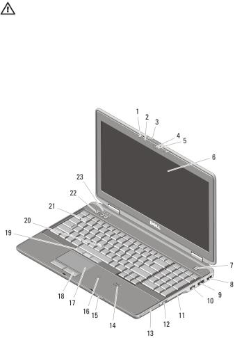
Figure 1. Front View
1. |
microphone |
3. |
camera |
2. |
display release latch |
4. |
camera status light |
Regulatory Model: : P25G, P19F, P25G
Regulatory Type: : P25G001, P19F001,
P25G002
2011 - 9
5.display latch
6.display
7.power button
8.eSATA/USB 2.0 connector
9.USB 3.0 connector
10.powered USB 3.0 connector
11.volume control buttons
12.wireless switch
13.optical drive
14.ExpressCard slot
15.fingerprint reader
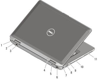
Figure 2. Back View
1.HDMI connector
2.security cable slot
3.modem connector
4.device status lights (power, hard disk, and battery)
5.power connector
6.network connector
16.Secure Digital (SD) memory-card reader
17.contactless smart card reader
18.touchpad buttons (2)
19.touchpad
20.trackstick buttons (3)
21.trackstick
22.keyboard
23.device status lights (hard disk, battery, and wireless)
7.USB 2.0 connector
8.VGA connector
9.audio connector
10.cooling vents
11.smart card slot
2
WARNING: Do not block, push objects into, or allow dust to accumulate in the air vents. Do not store your Dell computer in a low-airflow environment, such as a closed briefcase, while it is running. Restricting the airflow can damage the computer or cause a fire. The computer turns on the fan when the computer gets hot. Fan noise is normal and does not indicate a problem with the fan or the computer.
Latitude E6530 Front and Back View
Figure 3. Front View |
|
|
|
1. |
display latch |
8. |
HDMI connector |
2. |
microphone |
9. |
eSATA/USB 2.0 connector |
3. |
display release latch |
10. |
powered USB 3.0 connector |
4. |
camera |
11. |
optical drive |
5. |
camera status light |
12. |
wireless switch |
6. |
display |
13. |
ExpressCard slot |
7. |
power button |
14. |
fingerprint reader |
3
15.Secure Digital (SD) memory-card reader
16.contactless smart card reader
17.touchpad
18.touchpad buttons (2)
19.trackstick buttons (3)
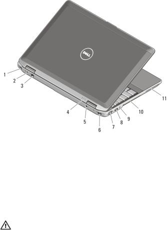
Figure 4. Back View
1.network connector
2.security cable slot
3.modem connector
4.device status lights (power, hard disk, and battery)
5.power connector
6.USB 2.0 connector
20.trackstick
21.keyboard
22.volume control buttons
23.device status lights (hard disk, battery, and wireless)
7.VGA connector
8.USB 3.0 connector
9.audio connector
10.cooling vents
11.smart card slot
WARNING: Do not block, push objects into, or allow dust to accumulate in the air vents. Do not store your Dell computer in a low-airflow environment, such as a closed briefcase, while it is running. Restricting the airflow can damage the computer or cause a fire. The computer turns on the fan when the computer gets hot. Fan noise is normal and does not indicate a problem with the fan or the computer.
4
Loading...