


 Loading...
Latitude 5290 2-in-1
Owner's Manual
Regulatory Model: T17G
Regulatory Type: T17G002
Notes, cautions, and warnings

 NOTE: A NOTE indicates important information that helps you make better use of your product.

 CAUTION: A CAUTION indicates either potential damage to hardware or loss of data and tells you how to avoid the problem.
 WARNING: A WARNING indicates a potential for property damage, personal injury, or death.
© 2016 Dell Inc. or its subsidiaries. All rights reserved. This product is protected by U.S. and international copyright and intellectual property laws. Dell and the Dell logo are trademarks of Dell Inc. in the United States and/or other jurisdictions. All other marks and names mentioned herein may be trademarks of their respective companies.
2017 - 12
Rev. A00

1
Working on your computer
Safety precautions
The safety precautions chapter details the primary steps to be taken before performing any disassembly instructions.
Observe the following safety precautions before you perform any installation or break/•x procedures involving disassembly or reassembly:
•Turn oƒ the system and all attached peripherals.
•Disconnect the system and all attached peripherals from AC power.
•Disconnect all network cables, telephone, and telecommunications lines from the system.
•Use an ESD •eld service kit when working inside any notebook to avoid electrostatic discharge (ESD) damage.
•After removing any system component, carefully place the removed component on an anti-static mat.
•Wear shoes with non-conductive rubber soles to reduce the chance of getting electrocuted.
Standby power
Dell products with standby power must be unplugged before you open the case. Systems that incorporate standby power are essentially powered while turned oƒ. The internal power enables the system to be remotely turned on (wake on LAN) and suspended into a sleep mode and has other advanced power management features.
Unplugging, pressing and holding the power button for 15 seconds should discharge residual power in the system board, notebooks
Bonding
Bonding is a method for connecting two or more grounding conductors to the same electrical potential. This is done through the use of a •eld service electrostatic discharge (ESD) kit. When connecting a bonding wire, ensure that it is connected to bare metal and never to a painted or non-metal surface. The wrist strap should be secure and in full contact with your skin, and ensure that you remove all jewelry such as watches, bracelets, or rings prior to bonding yourself and the equipment.
Electrostatic discharge — ESD protection
ESD is a major concern when you handle electronic components, especially sensitive components such as expansion cards, processors, memory DIMMs, and system boards. Very slight charges can damage circuits in ways that may not be obvious, such as intermittent problems or a shortened product life span. As the industry pushes for lower power requirements and increased density, ESD protection is an increasing concern.
Due to the increased density of semiconductors used in recent Dell products, the sensitivity to static damage is now higher than in previous Dell products. For this reason, some previously approved methods of handling parts are no longer applicable.
Two recognized types of ESD damage are catastrophic and intermittent failures.
•Catastrophic – Catastrophic failures represent approximately 20 percent of ESD-related failures. The damage causes an immediate and complete loss of device functionality. An example of catastrophic failure is a memory DIMM that has received a static shock and immediately generates a "No POST/No Video" symptom with a beep code emitted for missing or nonfunctional memory.
•Intermittent – Intermittent failures represent approximately 80 percent of ESD-related failures. The high rate of intermittent failures means that most of the time when damage occurs, it is not immediately recognizable. The DIMM receives a static shock, but the
Working on your computer |
3 |
|
|

tracing is merely weakened and does not immediately produce outward symptoms related to the damage. The weakened trace may take weeks or months to melt, and in the meantime may cause degradation of memory integrity, intermittent memory errors, etc.
The more difficult type of damage to recognize and troubleshoot is the intermittent (also called latent or "walking wounded") failure.
Perform the following steps to prevent ESD damage:
•Use a wired ESD wrist strap that is properly grounded. The use of wireless anti-static straps is no longer allowed; they do not provide adequate protection. Touching the chassis before handling parts does not ensure adequate ESD protection on parts with increased sensitivity to ESD damage.
•Handle all static-sensitive components in a static-safe area. If possible, use anti-static floor pads and workbench pads.
•When unpacking a static-sensitive component from its shipping carton, do not remove the component from the anti-static packing material until you are ready to install the component. Before unwrapping the anti-static packaging, ensure that you discharge static electricity from your body.
•Before transporting a static-sensitive component, place it in an anti-static container or packaging.
ESD field service kit
The unmonitored Field Service kit is the most commonly used service kit. Each Field Service kit includes three main components: anti-static mat, wrist strap, and bonding wire.
Components of an ESD field service kit
The components of an ESD •eld service kit are:
•Anti-Static Mat – The anti-static mat is dissipative and parts can be placed on it during service procedures. When using an anti-static mat, your wrist strap should be snug and the bonding wire should be connected to the mat and to any bare metal on the system being worked on. Once deployed properly, service parts can be removed from the ESD bag and placed directly on the mat. ESD-sensitive items are safe in your hand, on the ESD mat, in the system, or inside a bag.
•Wrist Strap and Bonding Wire – The wrist strap and bonding wire can be either directly connected between your wrist and bare metal on the hardware if the ESD mat is not required, or connected to the anti-static mat to protect hardware that is temporarily placed on the mat. The physical connection of the wrist strap and bonding wire between your skin, the ESD mat, and the hardware is known as bonding. Use only Field Service kits with a wrist strap, mat, and bonding wire. Never use wireless wrist straps. Always be aware that the internal wires of a wrist strap are prone to damage from normal wear and tear, and must be checked regularly with a wrist strap tester in order to avoid accidental ESD hardware damage. It is recommended to test the wrist strap and bonding wire at least once per week.
•ESD Wrist Strap Tester – The wires inside of an ESD strap are prone to damage over time. When using an unmonitored kit, it is a best practice to regularly test the strap prior to each service call, and at a minimum, test once per week. A wrist strap tester is the best method for doing this test. If you do not have your own wrist strap tester, check with your regional office to •nd out if they have one. To perform the test, plug the wrist-strap's bonding-wire into the tester while it is strapped to your wrist and push the button to test. A green LED is lit if the test is successful; a red LED is lit and an alarm sounds if the test fails.
•Insulator Elements – It is critical to keep ESD sensitive devices, such as plastic heat sink casings, away from internal parts that are insulators and often highly charged.
•Working Environment – Before deploying the ESD Field Service kit, assess the situation at the customer location. For example, deploying the kit for a server environment is diƒerent than for a desktop or portable environment. Servers are typically installed in a rack within a data center; desktops or portables are typically placed on office desks or cubicles. Always look for a large open flat work area that is free of clutter and large enough to deploy the ESD kit with additional space to accommodate the type of system that is being repaired. The workspace should also be free of insulators that can cause an ESD event. On the work area, insulators such as Styrofoam and other plastics should always be moved at least 12 inches or 30 centimeters away from sensitive parts before physically handling any hardware components
•ESD Packaging – All ESD-sensitive devices must be shipped and received in static-safe packaging. Metal, static-shielded bags are preferred. However, you should always return the damaged part using the same ESD bag and packaging that the new part arrived in. The ESD bag should be folded over and taped shut and all the same foam packing material should be used in the original box that the new part arrived in. ESD-sensitive devices should be removed from packaging only at an ESD-protected work surface, and parts should never be placed on top of the ESD bag because only the inside of the bag is shielded. Always place parts in your hand, on the ESD mat, in the system, or inside an anti-static bag.
•Transporting Sensitive Components – When transporting ESD sensitive components such as replacement parts or parts to be returned to Dell, it is critical to place these parts in anti-static bags for safe transport.
4 Working on your computer

ESD protection summary
It is recommended that all •eld service technicians use the traditional wired ESD grounding wrist strap and protective anti-static mat at all times when servicing Dell products. In addition, it is critical that technicians keep sensitive parts separate from all insulator parts while performing service and that they use anti-static bags for transporting sensitive components.
Transporting sensitive components
When transporting ESD sensitive components such as replacement parts or parts to be returned to Dell, it is critical to place these parts in anti-static bags for safe transport.
Lifting equipment
Adhere to the following guidelines when lifting heavy weight equipment:

 CAUTION: Do not lift greater than 50 pounds. Always obtain additional resources or use a mechanical lifting device.
1Get a •rm balanced footing. Keep your feet apart for a stable base, and point your toes out.
2Tighten stomach muscles. Abdominal muscles support your spine when you lift, oƒsetting the force of the load.
3Lift with your legs, not your back.
4Keep the load close. The closer it is to your spine, the less force it exerts on your back.
5Keep your back upright, whether lifting or setting down the load. Do not add the weight of your body to the load. Avoid twisting your body and back.
6Follow the same techniques in reverse to set the load down.
Before Working Inside Your Tablet
Use the following safety guidelines to help protect your tablet from potential damage and to help to ensure your personal safety. Unless otherwise noted, each procedure included in this document assumes that the following condition exists:
•You have read the safety information that shipped with your tablet.
WARNING: Before working inside your tablet, read the safety information that shipped with your tablet. For additional safety best practices information, see the Regulatory Compliance Homepage at www.dell.com/regulatory_compliance
CAUTION: Many repairs may only be done by a certified service technician. You should only perform troubleshooting and simple repairs as authorized in your product documentation, or as directed by the online or telephone service and support team. Damage due to servicing that is not authorized by Dell is not covered by your warranty. Read and follow the safety instructions that came with the product.
CAUTION: To avoid electrostatic discharge, ground yourself by using a wrist grounding strap or by periodically touching an unpainted metal surface, such as a connector on the back of the tablet.
CAUTION: Handle components and cards with care. Do not touch the components or contacts on a card. Hold a card by its edges or by its metal mounting bracket.
CAUTION: When you disconnect a cable, pull on its connector or on its pull-tab, not on the cable itself. Some cables have connectors with locking tabs; if you are disconnecting this type of cable, press in on the locking tabs before you disconnect the cable. As you pull connectors apart, keep them evenly aligned to avoid bending any connector pins. Also, before you connect a cable, ensure that both connectors are correctly oriented and aligned.

 NOTE: The color of your tablet and certain components may appear differently than shown in this document.
To avoid damaging your tablet, perform the following steps before you begin working inside the tablet.
1Ensure that your work surface is flat and clean to prevent the tablet cover from being scratched.
2Turn oƒ your tablet.
Working on your computer |
5 |
|
|

3If the tablet is connected to a docking device (docked) such as the optional docking station or keyboard dock, un-dock it.
4Disconnect the power adapter from the tablet.
5Press and hold the power button for a few seconds to remove the flea power from the system board.

 CAUTION: To guard against electrical shock, always unplug your tablet from the electrical outlet.
CAUTION: Before touching anything inside your tablet, ground yourself by touching an unpainted metal surface, such as the metal at the back of the tablet. While you work, periodically touch an unpainted metal surface to dissipate static electricity, which could harm internal components.
6 Remove the storage SD card from the tablet.
After working inside your tablet

 CAUTION: Leaving stray or loose screws inside your tablet may severely damage your tablet.
1Replace all screws and ensure that no stray screws remain inside your tablet.
2Connect any external devices, peripherals, and cables that you removed before working on your tablet.
3Replace any media card, SIM card, and any other parts that you removed before working on your tablet.
4Connect your tablet and all attached devices to their electrical outlets.
5Turn on your tablet.
Turning off Your Tablet
Turning oƒ your tablet completely shuts down your tablet. You can turn oƒ your tablet by two ways:
•Using power button
•Using charms menu
1 To turn oƒ your tablet using power button:
a Press and hold the Power button  until you see “Slide to shut down your PC” on the screen.
6 Working on your computer
NOTE: After you press and hold the Power button, by default, the “Slide to shut down your PC” screen displays only in
Venue 11 Pro 7130. For Venue 11 pro 7130 vPro and Venue 11 Pro 7139, by default, the tablet enters sleep mode. However, if you change the power button setting to shut down, the tablet shuts down. To change the power button setting, go to Control Panel > Power Options > Change Plan Setting > Change Advanced Power Settings. To access Control Panel, swipe at the right edge of the screen, tap Search, enter Control Panel in the search box, and then click Control Panel.
b Slide to shut down your tablet.
NOTE: You can also turn off your tablet without sliding down the screen. Press and hold the Power  button for >10 seconds to turn off your tablet. You can perform this force shutdown, if your tablet is not responding / behaving unexpectedly or touch is not working.
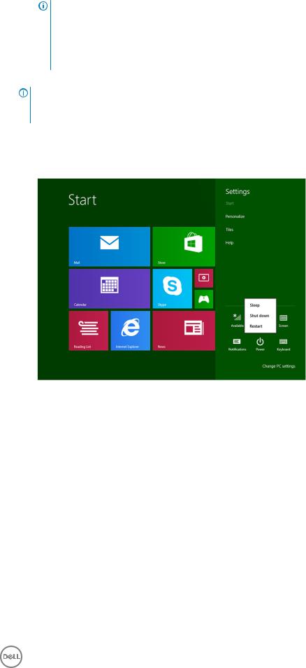
2 To turn oƒ your tablet using the charms menu:
aSwipe from the right edge of the display to access the Charms menu.
bTouch Settings  —> Power
  —> Shut down to turn oƒ the tablet.
Working on your computer |
7 |
|
|

2
Removing and installing components
This section provides detailed information on how to remove or install the components from your computer.
Recommended tools
The procedures in this document may require the following tools:
•Phillips screwdriver
•#0 Phillips head screwdriver
•#1 Phillips head screwdriver
•Plastic scribe
Screw list
Table 1. Latitude 5285 2-in-1 Screw size list
Component |
M2.0x 1.1+1.7 |
M2.0X4.0 |
M1.6x3.0 |
M2.0X2.5 |
M1.6x3.0 |
M2.0X2.0 |
M2.0X3.5 |
|
|
|
|
|
|
|
|
Back cover |
3 |
|
|
|
|
|
|
|
|
|
|
|
|
|
|
Battery |
|
4 |
|
|
|
|
|
|
|
|
|
|
|
|
|
Heat sink |
|
|
|
4 |
|
|
|
|
|
|
|
|
|
|
|
Hinges |
|
4 |
|
|
|
|
|
|
|
|
|
|
|
|
|
Display panel |
|
|
6 |
|
|
|
|
|
|
|
|
|
|
|
|
System fan |
|
2 |
|
|
|
|
|
|
|
|
|
|
|
|
|
WWAN card |
|
|
|
|
|
|
1 |
|
|
|
|
|
|
|
|
WLAN card |
|
|
|
|
|
|
1 |
|
|
|
|
|
|
|
|
Smart card cage |
|
|
|
3 |
|
|
|
|
|
|
|
|
|
|
|
SSD card |
|
|
|
1 |
|
|
|
|
|
|
|
|
|
|
|
Docking bracket |
|
|
|
|
|
2 |
|
|
|
|
|
|
|
|
|
Kickstand |
|
|
|
|
4 |
|
|
|
|
|
|
|
|
|
|
Camera module |
|
|
|
|
3 |
|
|
|
|
|
|
|
|
|
|
Antenna module |
|
|
|
|
1 |
|
|
|
|
|
|
|
|
|
|
System board |
|
|
|
4 |
|
|
|
|
|
|
|
|
|
|
|
Removing and Installing components
This section provides detailed information on how to remove or install the components from your tablet.
8 Removing and installing components

micro SD - micro SIM card
uSIM cards can be installed only on tablets shipped with WWAN module.
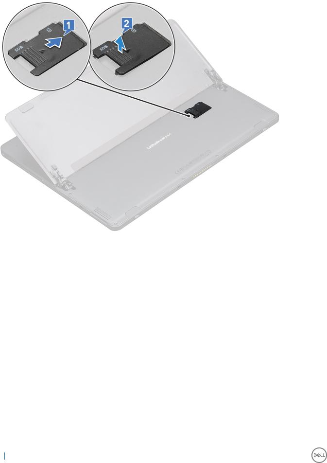
1Flip the tablet on a plane and flat surface.
2Press the two Kickstand auto-release pegs, and slide the kickstand [1],[2].

 NOTE: Or Pull and slide the kickstand to open, ensure NOT to pull more than 135° to avoid damage to the hinges.
NOTE: Ensure to turn off or disconnect power, to drain †ea power before installing the micro SD and/or microSIM.
3Slide the kickstand to an angle 135°, to microSD and micro-SIM cards slot.
4Slide the microSD / micro-SIM card cover towards 3° clock [1] and pull the cover [2].
5Insert the SD card / micro-SIM cards and a lign the cover with the groove on the tablet and slide it inside to secure the microSD and the micro-SIM cards.
Removing and installing components |
9 |
|
|
6 Perform the same steps to remove the microSD / micro-SIM cards
Display Assembly
Removing the display assembly
1Follow the procedure in Before working inside your tablet.
2Remove the:
a uSIM/microSD card

 NOTE: uSIM card slot is available only on tablets shipping with WWAN module.
3 Open the kickstand by holding the tablet vertically and pressing it down. Place the tablet with the display facing down.
10 Removing and installing components

 NOTE: You can also open the kickstand from the speaker recess area.
4 Place the tablet on a flat surface and lift the stand to reveal the base of the tablet.
5 To release the display assembly:
a Remove the M1.6 x 3.0 (6) screws that secure the base cover to the tablet [1].
Removing and installing components |
11 |
|
|

b Close the kickstand [2] and flip the tablet to view the display.
6 Use a plastic scribe [1] to pry the edges [2] of the display panel starting from the bottom side •rst (near the docking port).
12 Removing and installing components
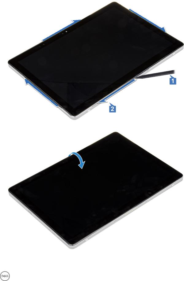

 NOTE: Ensure to pry from the docking port and gently moving clockwise to avoid damage to the plastic clips.
7 Flip the display panel on a plane surface with the LCD panel upwards.
8 To disconnect the cables:
a Push and disconnect the battery cable on the system board [1].
Removing and installing components |
13 |
|
|

b Pull and disconnect the display cable on the system board [2].
9 Lift the display assembly from the tablet.
Installing the display assembly
1Place the display panel on a plane surface.
2Connect the display cable to the connector on the system board
3Connect the battery cable to the connector on the system board.
4Install the display panel on the tablet and press the edges until they snap in.
5Flip the tablet and open the kickstand.
6Replace the M1.6 x 3.0 screws to secure the tablet to the display panel.
7Install the:
a uSIM/micro SD card
8 Follow the procedure in After working inside your tablet.
PCIe Solid State Drive (SSD)
Removing the SSD module
1Follow the procedure in Before working inside your tablet.
2Remove the:
a uSIM/microSD card

 NOTE: uSIM card slot is available only on tablets shipping with WWAN module.
14 Removing and installing components
b display panel
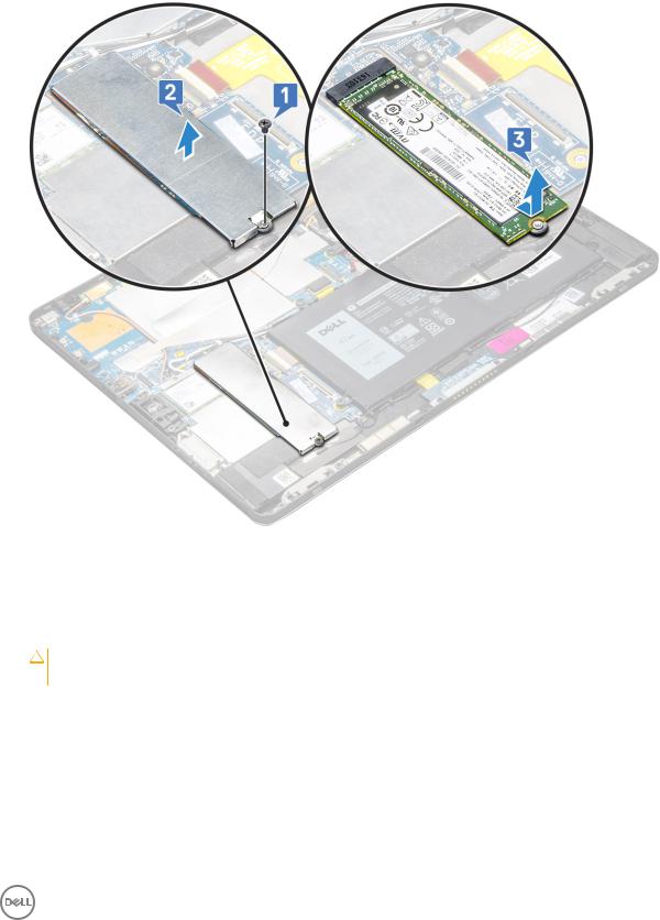
3 To remove the SSD module:
aRemove the M2.0 x 2.5 screw securing the SSD shield [1].
bLift the SSD shield away from the tablet [2].
cSlide and lift the SSD module from the slot on the tablet [3].

 NOTE: Ensure NOT to lift the SSD card by an angle more than 15°.
Installing SSD module
1Insert the SSD module into the connector on the system board.
2Install the SSD shield on the SSD module.
CAUTION: Align the five clips heads into the system board clips holes, to install the shield properly. Ensure to insert the clips with caution, as the clips are small and delicate. Mishandling damages the clips head and needs replacing the shield.
3 Replace the M2.0 x 2.5 screw to secure SSD shield.

 NOTE: Align the shield carefully to avoid damage to the clips heads.
4 Install the:
aDisplay panel
buSIM/microSD
Micro-SIM card is installed only on tablets shipped with WWAN module.
5 Follow the procedure in after working inside your tablet.
Removing and installing components |
15 |
|
|

WLAN card
Removing the WWAN card
1Follow the procedure in Before working inside your tablet.
2Remove the:
a uSIM/micrSD card

 NOTE: uSIM card slot is available only on tablets shipping with WWAN module. b display panel
3 To remove the WWAN card:
aRemove the M2.0 x 3.5 screw securing the WWAN bracket [1] and lift the bracket [2].
bDisconnect the antenna cables from the WWAN card [3].
cLift and slide the WLAN card from the connector on the system board [4].

 NOTE: Ensure to lift the WWAN card by an angle NOT more than 20°.
Installing the WLAN card
1Insert the WLAN card into the connector on the system board.
2Connect the antenna cables to the WLAN card.
16 Removing and installing components

3Insert the WLAN bracket to the WLAN card.
4Replace the M2.0 x 3.5 screw to secure WLAN bracket.
5Install the:
adisplay panel
buSIM/microSD

 NOTE: uSIM card is installed only on tablets shipping with WWAN module.
6 Follow the procedure in After working inside your tablet.
Speaker
Removing the speaker
1Follow the procedure in Before working inside your tablet.
2Remove the:
a Micro SIM/micro SD card

 NOTE: Micro SIM card slot is available only on tablets shipping with WWAN module. b display panel
3 To remove the speaker:
a Lift the latch and release the speaker cable from the connector [1].
NOTE: Ensure to remove the SSD, to create more space to pry off the speakers.
b Un-route the speaker cable from the routing clips with a plastic scribe [2].
NOTE: Ensure to remove the M.2 2280 SSD and M.2 2280 SSD shielding cover, to avoid obstruction in un-routing the speaker cable.
Removing and installing components |
17 |
|
|

c Release the speakers from the tablet [3].

 NOTE: The speaker is attached with an adhesive, ensure to pull gently for reuse of the tape in installing the speaker.
Installing speaker
1Insert the speaker in the block on the system board.
2Connect the cables to the system board.
3Press the speaker to glue it to the adhesive paste on the system.
4Install the:
aDisplay panel
buSIM/microSD

 NOTE: uSIM card is installed only on tablets shipping with WWAN module.
5 Follow the procedure in After working inside your tablet.
Battery
Removing the battery
1Follow the procedure in Before working inside your tablet.
2Remove the:
a uSIM/micro SD card

 NOTE: uSIM card slot is available only on tablets shipping with WWAN module. b display panel
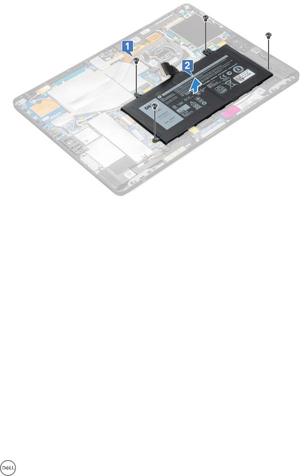
3 To remove the battery:
aRelease the adhesive tape that secures the battery connector to the system board.
bDisconnect the battery cable from the connector on the system board.

 NOTE: Ensure to pull the cable by the lever of the battery connector, to avoid damage to the pin.
cRemove the M2.0 x 4.0 screws (4) that secure the battery to the tablet [1].
dLift the battery from the tablet [2].
18 Removing and installing components
Installing the battery
1Insert the battery into the slot on the tablet.
2Replace the M2.0 x 4.0 screws to secure the battery to the tablet.
3Connect the battery connector to the system board and release the adhesive tape that secures the connector.
4Install the:
adisplay panel
buSIM/microSD card

 NOTE: uSIM card is installed only on tablets shipping with WWAN module.
5 Follow the procedure in After working inside your tablet.
System Fan
Removing the system fan
1Follow the procedure in Before working inside your tablet.
2Remove the:
a uSIM/microSD card

 NOTE: Micro-SIM card slot is available only on tablets shipped with WWAN module. b Display panel
3 To remove the system fan:
aDisconnect the system fan cable from the system board [1].
bRemove the M2.0 x 4.0 screws (2) that secure the system fan [2].
Removing and installing components |
19 |
|
|

c Lift the system fan from the tablet system chassis [3].
Installing the system fan
1Align the system fan with screw holders on the system board.
2Replace the M2.0 x 3.0 screws to secure the system fan to the system board.
3Connect the system fan cable to the system board.
4Install the:
a display panel

 NOTE: uSIM card is installed only on tablets shipping with WWAN module. b uSIM/microSD card
5 Follow the procedure in After working inside your tablet.
Heat Sink
Removing heat sink assembly
1Follow the procedure in Before working inside your tablet.
2Remove the:
a Micro-SIM and/or microSD card
20 Removing and installing components

 NOTE: Micro-SIM card slot is available only on tablets shipping with WWAN module. b Display panel
3 To remove the heat sink assembly:
a Peel the conductive tapes that secure the shielding cover.
NOTE: Ensure to peel off the tape carefully, as any damage to the tape will need to raise a new order for conductive tapes. The tape secures the IR camera cable from any damage. Ensure to fix the tapes while installing or replacing the component.
NOTE: Ensure to peel off the conductive tape, if the system heatsink is shipped with a tape.
b Lift the shielding covers that secure the heat sink assembly .
4 To remove the heat sink assembly:
aLoosen the M2.0 x 2.5 captive screws (4) that secure the heat sink assembly to the tablet [1].
bLift the heat sink assembly from the tablet [2].
Removing and installing components |
21 |
|
|

Installing heat sink assembly
1Align the heat sink assembly with screw holders on the system board.
2Replace the M2.0 x 2.5 screws to secure the heat sink to the system board.

 NOTE: Tighten the screws on the system board in the order of the callout numbers [1, 2, 3, 4] as indicated on the heat sink.
3Install the shielding covers on the heat sink assembly.
4Affix the conductive tapes to secure the shielding covers.
5Replace the shielding covers to cover the heat sink assembly.

 NOTE: The shield covers can break if not handled carefully.
6 Install the:
adisplay panel
buSIM/microSD card

 NOTE: uSIM card is installed only on tablets shipping with WWAN module.
7 Follow the procedure in After working inside your tablet
Front facing camera
Removing front camera
1Follow the procedure in Before working inside your tablet.
2Remove the:
a Micro-SIM and/or microSD card
22 Removing and installing components

 NOTE: Micro-SIM card slot is available only on tablets shipping with WWAN module. b Display panel
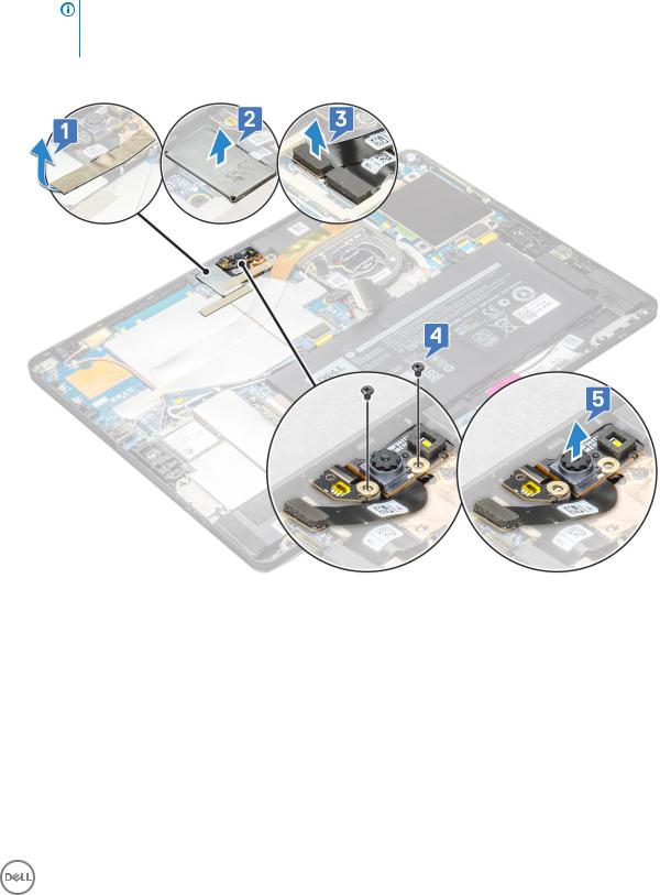
3 To remove the front camera:
a Remove the conductive tape covering the shielding cover [1].

 NOTE: Ensure to pull the conductive tape gently to reuse in installing the front camera.
bLift the shielding cover covering the front cameracable connected to the system board[2].
cUse a plastic scribe to disconnect the front camera cable [3]
NOTE: Ensure to peel off the adhesive tape that secures the front camera to the rear camera. The front camera cable is glued to the rear camera, ensure to gently peel off, to remove the screw that secures the rear camera to the system board.
dRemove the M1.6 x 3.0 screws (2) securing the front camera module [4].
eLift the front camera module from the tablet [5].
Installing the front camera
1Insert the camera module into the slot on the tablet.
2Replace the M1.6 x 3.0 screws to secure the front camera module.
3Connect the front camera cable to the system board.
4Place the covering shield to cover the front camera module.

 NOTE: Handle the covering shield with care else it may break.
5Affix the tape to secure the shield cover.
6Install the:
adisplay panel
buSIM/microSD card
Removing and installing components |
23 |
|
|


 NOTE: uSIM card is installed only on tablets shipping with WWAN module.
7 Follow the procedure in After working inside your tablet.
Rear facing camera
Removing rear camera
1Follow the procedure in Before working inside your tablet.
2Remove the:
a uSIM/microSD
NOTE: Micro-SIM card slot is available only on tablets shipping with WWAN module.
bDisplay panel
cfront facing camera
3 To remove the rear camera:
aDisconnect the rear camera cable from the system board [1].
bRemove the M1.6 x 3.0 screw (1) securing the rear camera module [2].
cLift the camera module from the tablet [3].
Installing the rear camera
1Insert the rear camera module into the slot on the tablet.
2Replace the M1.6 x 3.0 screw to secure the rear camera module.
24 Removing and installing components

3Connect the rear camera cable to the system board.
4Install the:
afront camera
bdisplay panel
cuSIM/microSD

 NOTE: uSIM card is installed only on tablets shipping with WWAN module.
5 Follow the procedure in After working inside your tablet.
Smart Card Cage
Removing the smart card cage

 NOTE: Always remove the smart card from the smart card reader.
1Follow the procedure in Before working inside your tablet.
2Remove the:
a uSIM/microSD card

 NOTE: uSIM card slot is available only on tablets shipping with WWAN module. b display panel
3 To disconnect the cables:
aLift the latch and dDisconnect the smart card cable from the smart card cage [1].
bRemove the M2.0 x 2.5 screws (3) from the smart card module [2].
cLift the smart card cage from the tablet [3].
Removing and installing components |
25 |
|
|

Installing the smart card cage
1Insert the smart cage into the slot on the tablet.
2Replace the M2.0 x 2.5 screws screws to secure the smart card cage to the tablet.
3Connect the smart cable to the smart card module.
4Install the:
adisplay panel
buSIM/microSD card

 NOTE: uSIM card is installed only on tablets shipping with WWAN module.
5 Follow the procedure in After working inside your tablet.
Docking board
Removing the docking board
1Follow the procedure in Before working inside your tablet.
2Remove the:
a uSIM/microSD card
NOTE: uSIM card slot is available only on tablets shipping with WWAN module.
bdisplay panel
cbattery
3 To release the docking board:
aLift the latch and dDisconnect the docking board cable from the system board [1].
bPeel the docking board cable from adhesive on the tablet [2].
cRemove the M2.0 x 2.0 screws (2) securing the docking board bracket to the docking board [3].
dLift the docking board from the tablet [4].
26 Removing and installing components
Loading...