


 Loading...
Dell Latitude E5570
Owner's Manual
Regulatory Model: P48F
Regulatory Type: P48F001
Notes, cautions, and warnings

 NOTE: A NOTE indicates important information that helps you make better use of your product.

 CAUTION: A CAUTION indicates either potential damage to hardware or loss of data and tells you how to avoid the problem.
 WARNING: A WARNING indicates a potential for property damage, personal injury, or death.
© 2016 2018 Dell Inc. or its subsidiaries. All rights reserved. Dell, EMC, and other trademarks are trademarks of Dell Inc. or its subsidiaries. Other trademarks may be trademarks of their respective owners.
2018 - 10
Rev. A05

Contents
1 Working on your computer............................................................................................................................. |
6 |
Safety instructions............................................................................................................................................................. |
6 |
Before working inside your computer.............................................................................................................................. |
6 |
Turning off your computer................................................................................................................................................. |
7 |
After working inside your computer................................................................................................................................. |
7 |
Keyboard short-cut key functions.................................................................................................................................... |
7 |
2 Disassembly and reassembly.......................................................................................................................... |
9 |
Recommended tools.......................................................................................................................................................... |
9 |
Installing the Subscriber Identification Module SIM card.............................................................................................. |
9 |
Removing the Subscriber Identification Module SIM card........................................................................................... |
9 |
Removing the base cover................................................................................................................................................ |
10 |
Installing the base cover.................................................................................................................................................. |
10 |
Lithium-ion battery precautions...................................................................................................................................... |
10 |
Removing the battery....................................................................................................................................................... |
11 |
Installing the battery......................................................................................................................................................... |
12 |
Removing the hard drive assembly................................................................................................................................. |
12 |
Removing the hard drive from the hard drive bracket................................................................................................. |
13 |
Installing the hard drive into the hard drive bracket..................................................................................................... |
14 |
Installing the hard drive assembly................................................................................................................................... |
14 |
Installing the optional M.2 SSD....................................................................................................................................... |
14 |
Removing the optional M.2 Solid State Drive SSD....................................................................................................... |
15 |
Installing the optional PCIe SSD..................................................................................................................................... |
15 |
Removing the optional PCIe SSD................................................................................................................................... |
15 |
Removing the memory module....................................................................................................................................... |
16 |
Installing the memory module......................................................................................................................................... |
16 |
Removing the WLAN card............................................................................................................................................... |
17 |
Installing the WLAN card................................................................................................................................................. |
17 |
Removing the WWAN card.............................................................................................................................................. |
17 |
Installing the WWAN card................................................................................................................................................ |
18 |
Removing the power connector port............................................................................................................................. |
18 |
Installing the power connector port............................................................................................................................... |
19 |
Removing the keyboard .................................................................................................................................................. |
19 |
Installing the keyboard..................................................................................................................................................... |
20 |
Removing the display assembly..................................................................................................................................... |
20 |
Installing the display assembly........................................................................................................................................ |
22 |
Removing the display bezel............................................................................................................................................. |
22 |
Installing the display bezel............................................................................................................................................... |
23 |
Removing the display panel............................................................................................................................................ |
23 |
Installing the display panel............................................................................................................................................... |
24 |
Removing the camera...................................................................................................................................................... |
24 |
Installing the camera........................................................................................................................................................ |
25 |
Removing the dock frame.............................................................................................................................................. |
25 |
Contents 3
Installing the dock frame................................................................................................................................................. |
27 |
Removing the touchpad button..................................................................................................................................... |
27 |
Installing the touchpad button........................................................................................................................................ |
28 |
Removing the optional SmartCard reader board......................................................................................................... |
28 |
Installing the optional SmartCard reader board............................................................................................................ |
29 |
Removing the optional finger print reader board......................................................................................................... |
29 |
Installing the optional finger print reader board........................................................................................................... |
30 |
Removing the LED board................................................................................................................................................ |
30 |
Installing the LED board................................................................................................................................................... |
31 |
Removing the heat sink assembly.................................................................................................................................. |
31 |
Installing the heat sink assembly.................................................................................................................................... |
32 |
Removing the coin cell battery....................................................................................................................................... |
32 |
Installing the coin cell battery......................................................................................................................................... |
33 |
Removing the speakers................................................................................................................................................... |
33 |
Installing the speakers..................................................................................................................................................... |
34 |
Removing the system board........................................................................................................................................... |
34 |
Installing the system board............................................................................................................................................. |
35 |
Removing the palmrest................................................................................................................................................... |
36 |
Installing the palmrest...................................................................................................................................................... |
36 |
3 System setup options.................................................................................................................................. |
38 |
Boot Sequence................................................................................................................................................................. |
38 |
Navigation keys................................................................................................................................................................ |
39 |
System Setup overview.................................................................................................................................................. |
39 |
Accessing System Setup................................................................................................................................................ |
39 |
General screen options.................................................................................................................................................... |
39 |
System Configuration screen options........................................................................................................................... |
40 |
Video screen options....................................................................................................................................................... |
42 |
Security screen options................................................................................................................................................... |
43 |
Secure Boot screen options............................................................................................................................................ |
44 |
Intel Software Guard Extensions screen options......................................................................................................... |
45 |
Performance screen options.......................................................................................................................................... |
45 |
Power Management screen options.............................................................................................................................. |
46 |
POST Behavior screen options....................................................................................................................................... |
47 |
Virtualization support screen options............................................................................................................................ |
48 |
Wireless screen options................................................................................................................................................... |
49 |
Maintenance screen options........................................................................................................................................... |
49 |
System Log screen options............................................................................................................................................. |
49 |
Updating the BIOS in Windows .................................................................................................................................... |
50 |
System and setup password.......................................................................................................................................... |
50 |
Assigning a system password and setup password............................................................................................... |
50 |
Deleting or changing an existing system and or setup password......................................................................... |
51 |
4 Technical specifications............................................................................................................................... |
52 |
System specifications...................................................................................................................................................... |
52 |
Processor specifications................................................................................................................................................. |
53 |
Memory specifications.................................................................................................................................................... |
53 |
4 Contents
Storage specifications..................................................................................................................................................... |
53 |
Audio specifications......................................................................................................................................................... |
53 |
Video specifications......................................................................................................................................................... |
54 |
Camera specifications..................................................................................................................................................... |
54 |
Communication specifications........................................................................................................................................ |
54 |
Port and connector specifications................................................................................................................................. |
54 |
Contactless smart card specifications.......................................................................................................................... |
55 |
Display specifications...................................................................................................................................................... |
55 |
Keyboard specifications.................................................................................................................................................. |
56 |
Touchpad specifications.................................................................................................................................................. |
56 |
Battery specifications...................................................................................................................................................... |
56 |
AC Adapter specifications............................................................................................................................................... |
57 |
Physical specifications..................................................................................................................................................... |
58 |
Environmental specifications.......................................................................................................................................... |
58 |
5 Diagnostics.................................................................................................................................................. |
59 |
Enhanced Pre-Boot System Assessment ePSA diagnostics...................................................................................... |
59 |
Device status lights.......................................................................................................................................................... |
60 |
Battery status lights......................................................................................................................................................... |
61 |
6 Contacting Dell............................................................................................................................................ |
62 |
Contents 5

1
Working on your computer
Safety instructions
Use the following safety guidelines to protect your computer from potential damage and to ensure your personal safety. Unless otherwise noted, each procedure included in this document assumes that the following conditions exist:
•You have read the safety information that shipped with your computer.
•A component can be replaced or, if purchased separately, installed by performing the removal procedure in the reverse order.
WARNING: Disconnect all power sources before opening the computer cover or panels. After you finish working inside the computer, replace all covers, panels, and screws before connecting to the power source.
WARNING: Before working inside your computer, read the safety information that shipped with your computer. For additional safety best practices information, see the Regulatory Compliance Homepage at www.dell.com/regulatory_compliance
CAUTION: Many repairs may only be done by a certified service technician. You should only perform troubleshooting and simple repairs as authorized in your product documentation, or as directed by the online or telephone service and support team. Damage due to servicing that is not authorized by Dell is not covered by your warranty. Read and follow the safety instructions that came with the product.
CAUTION: To avoid electrostatic discharge, ground yourself by using a wrist grounding strap or by periodically touching an unpainted metal surface that is grounded to ground yourself before you touch the computer to perform any disassembly tasks.
CAUTION: Handle components and cards with care. Do not touch the components or contacts on a card. Hold a card by its edges or by its metal mounting bracket. Hold a component such as a processor by its edges, not by its pins.
CAUTION: When you disconnect a cable, pull on its connector or on its pull-tab, not on the cable itself. Some cables have connectors with locking tabs; if you are disconnecting this type of cable, press in on the locking tabs before you disconnect the cable. As you pull connectors apart, keep them evenly aligned to avoid bending any connector pins. Also, before you connect a cable, ensure that both connectors are correctly oriented and aligned.

 NOTE: The color of your computer and certain components may appear differently than shown in this document.
Before working inside your computer
To avoid damaging your computer, perform the following steps before you begin working inside the computer.
1Ensure that you follow the Safety instructions.
2Ensure that your work surface is „at and clean to prevent the computer cover from being scratched.
3Turn off your computer.
CAUTION: To disconnect a network cable, first unplug the cable from your computer and then unplug the cable from the network device.
4Disconnect all the network cables from the computer.
5Disconnect your computer and all attached devices from the electrical outlets.
6Press and hold the power button while the computer is unplugged to ground the system board.
7Remove the cover.
CAUTION: Before touching anything inside your computer, ground yourself by touching an unpainted metal surface, such as the metal at the back of the computer. While you work, periodically touch an unpainted metal surface to dissipate static electricity, which could harm internal components.
6 Working on your computer

CAUTION: Make sure that you place the cooler outlet side of your system at least 5 cm away from wall to prevent system overheat.

 CAUTION: Your system cannot be placed crosswise and make sure that there is no equipment on the side cover.
Turning off your computer
After working inside your computer
After you complete any replacement procedure, ensure that you connect any external devices, cards, and cables before turning on your computer.
CAUTION: To avoid damage to the computer, use only the battery designed for this particular Dell computer. Do not use batteries designed for other Dell computers.
1Replace the battery.
2Replace the base cover.
3Connect any external devices, such as a port replicator or media base, and replace any cards, such as an ExpressCard.
4Connect any telephone or network cables to your computer.
CAUTION: To connect a network cable, first plug the cable into the network device and then plug it into the computer.
5Connect your computer and all attached devices to their electrical outlets.
6Turn on your computer.
Keyboard short-cut key functions
The following table lists the keyboard short-cut key functions. Do not type the + (plus) symbol when running a command.
Table 1. Keyboard short-cut key functions
|
System functions |
Ctrl+Shift+Esc |
Opens the Task Manager window. |
Fn+Esc |
Enables or disables FN function key features. |
Fn+F5 |
Enables or disables Number lock. |
Fn+F6 |
Enables or disables Scroll lock. |
Fn+F9 |
Launches the Windows Search charm. |
Fn+F10 |
Enables backlight keyboard mode. |
Fn+PrtScr |
Enables or disables the bluetooth. |
Fn+Ctrl |
Opens the application's context menu. This key has the same effect as the Application Key. |
|
Display functions |
Fn+F8 |
Switches the video image to the next display option. The options include the integrated display, an |
|
external monitor, and both displays simultaneously. |
Fn+F11 |
Decreases brightness on the integrated display only (not on an external monitor). |
Fn+F12 |
Increases brightness on the integrated display only (not on an external monitor). |
Fn+Home |
Toggle Radio On/Off |
Fn+End |
Sleep |
Working on your computer |
7 |
Fn+Insert
Fn+F1
Fn+F2
Fn+F3
Fn+F4
Windows Logo key + M Windows Logo key + Shift+M Windows Logo key +E Windows Logo key +R Windows Logo key +F Windows Logo key +Ctrl+F Windows Logo key+Pause
Power management
Enables system Standby.
Media/audio
Mutes or unmutes the system audio.
Decreases the audio volume.
Increases the audio volume.
Mutes or unmutes the built-in microphone.
Microsoft Windows logo key functions
Minimizes all open windows.
Maximizes all open windows.
Runs Windows Explorer.
Opens the Run dialog box.
Opens the Search Results dialog box.
Opens the Search Results-Computer dialog box (if the computer is connected to a network). Opens the System Properties dialog box.
8 Working on your computer
2
Disassembly and reassembly
Recommended tools
The procedures in this document require the following tools:
•Phillips #0 screwdriver
•Phillips #1 screwdriver
•Small plastic scribe
Installing the Subscriber Identification Module SIM card
1Follow the procedure in Before working inside your computer.
2Insert a paperclip or a SIM card removal tool into the pinhole to remove the SIM card tray [1].
3Place the SIM card on the SIM card tray [2].
4Push the SIM card tray into the slot until it clicks into place.
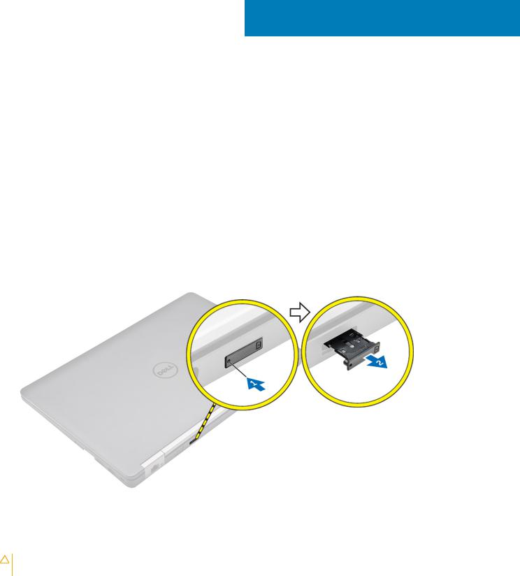
Removing the Subscriber Identification Module SIM card
CAUTION: Removing the SIM card when the computer is on may cause data loss or damage the card. Ensure your computer is turned off or the network connections are disabled.
1Insert a paperclip or a SIM card removal tool into the pinhole on the SIM card tray.
2Remove the SIM card from the SIM card tray.
3Push the SIM card tray into the slot until it clicks into place.
Disassembly and reassembly |
9 |
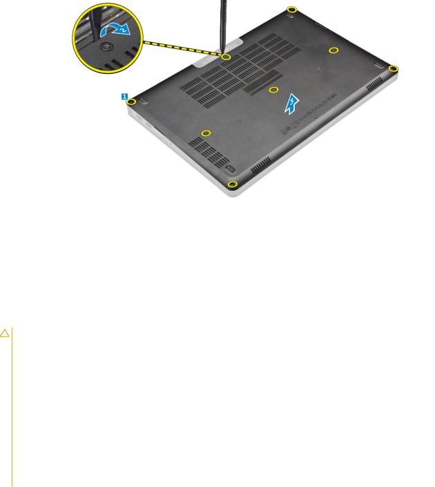
Removing the base cover
1Follow the procedure in Before working inside your computer.
2To remove the base cover:
aLoosen the screws that secure the base cover to the computer [1].
bLift the base cover from the edge and remove it from the computer [2, 3].

 NOTE: You may need a plastic scribe to lift the base cover from the edges.
Installing the base cover
1Align the base cover with the screw holders on the computer.
2Press the edges of the cover until it clicks into place.
3Tighten the screws to secure the base cover to the computer.
4Follow the procedure in After working inside your computer.
Lithium-ion battery precautions
CAUTION:
•Exercise caution when handling Lithium-ion batteries.
•Discharge the battery as much as possible before removing it from the system. This can be done by disconnecting the AC adapter from the system to allow the battery to drain.
•Do not crush, drop, mutilate, or penetrate the battery with foreign objects.
•Do not expose the battery to high temperatures, or disassemble battery packs and cells.
•Do not apply pressure to the surface of the battery.
•Do not bend the battery.
•Do not use tools of any kind to pry on or against the battery.
•If a battery gets stuck in a device as a result of swelling, do not try to free it as puncturing, bending, or crushing a Lithium-ion battery can be dangerous. In such an instance, the entire system should be replaced. Contact https://www.dell.com/support for assistance and further instructions.
•Always purchase genuine batteries from https://www.dell.com or authorized Dell partners and re-sellers.
10 Disassembly and reassembly
Removing the battery

 NOTE: If your computer supports the 6-cell battery, it will not support a hard drive.
NOTE: Discharge the battery as much as possible before removing from the system. This can be done by disconnecting the A/C adapter from the system (while the system is turned on) to allow the system to drain the battery.
1Follow the procedure in Before working inside your computer.
2Remove the base cover.
3To remove the battery:
aDisconnect the battery cable from the connector on the system board [1].
bRemove the screws that secure the battery to the computer [2].
cLift the battery away from the computer [3].
•Do not apply pressure to the surface of the battery
•Do not bend
•Do not use tools of any kind to pry on or against the battery
•If a battery cannot be removed within the constraints above, please contact Dell technical support
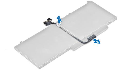
4 Unroute the cable from the routing channel [1] and remove the cable from the battery [2].

 NOTE: This step is applicable only for 3- and 4-cell battery.
Disassembly and reassembly |
11 |
Installing the battery

 NOTE: If your computer supports a 6-cell battery, it will not support a hard drive.
1Connect the battery cable to the connector on the battery.
2Route the battery cable through the routing channel on the battery.

 NOTE: This step is applicable only for a 3- and 4-cell battery.
3Insert the battery into the slot on the computer.
4Tighten the screws to secure the battery to the computer.
5Connect the battery cable to the connector on the system board.
6Install the base cover.
7Follow the procedure in After working inside your computer.
Removing the hard drive assembly
If the system is shipped with hard drive assembly perform the following steps.
1Follow the procedure in Before working inside your computer.
2Remove the:
abase cover
bbattery
3 To remove the hard drive assembly:
aDisconnect the hard drive cable from the connector on the system board [1] .
bRemove the screws that secure the hard drive assembly to the computer [2].
cLift the hard drive assembly away from the computer [3].
12 Disassembly and reassembly
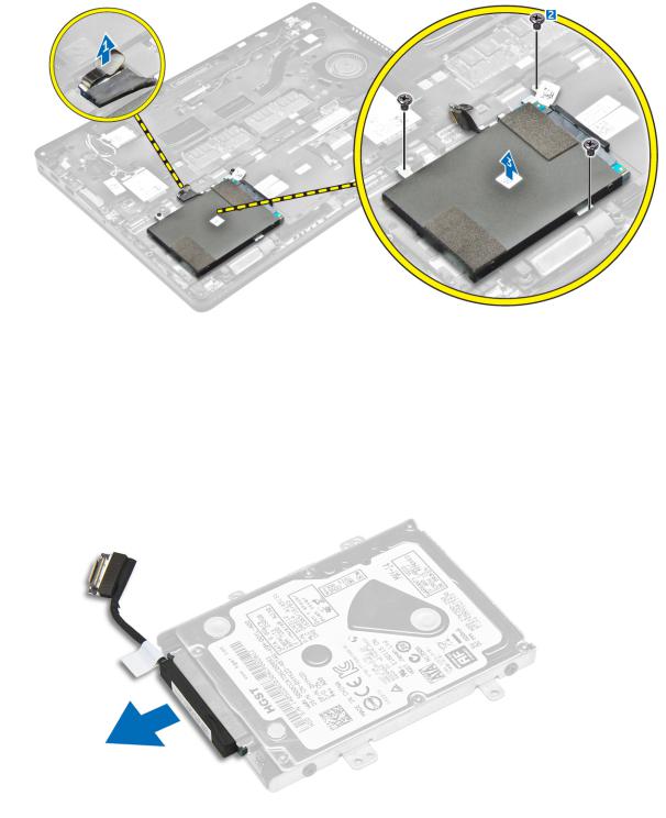
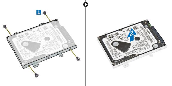
Removing the hard drive from the hard drive bracket
1Follow the procedure in Before working inside your computer.
2Remove the:
abase cover
bbattery
chard drive assembly
3 Pull the hard drive cable to remove it from the connector.
4 Remove the screws that secure the hard drive bracket to the hard drive [1] and lift the hard drive from the hard drive bracket [2].
Disassembly and reassembly |
13 |
Installing the hard drive into the hard drive bracket
1Align the screw holders on the hard drive with the screws on the hard drive bracket.
2Insert the hard drive into the hard drive bracket.
3Tighten the screws to secure the hard drive to the hard drive bracket.
4Install the:
ahard drive assembly
bbattery
cbase cover
5 Follow the procedure in After working inside your system.
Installing the hard drive assembly
If the system is shipped with hard drive assembly perform the following steps.
1Insert the hard drive assembly into the slot on the computer.
2Tighten the screws to secure the hard drive assembly to the computer.
3Connect the hard drive cable to the connector on the hard drive and on the system board.
4Install the:
abattery
bbase cover
5 Follow the procedures in After working inside your system.
Installing the optional M.2 SSD
If the system is shipped with M.2 SSD perform the following steps.
1Insert the SSD into the connector on the computer.
2Tighten the screw to secure the SSD to the computer.
3Install the:
abattery
bbase cover
4 Follow the procedure in After working inside your computer.
14 Disassembly and reassembly
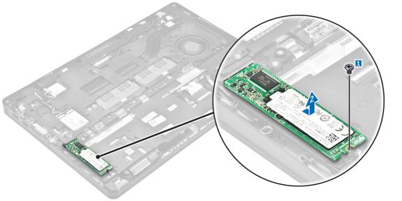
Removing the optional M.2 Solid State Drive SSD
If the system is shipped with M.2 SSD perform the following steps.
1Follow the procedure in Before working inside your computer.
2Remove the:
abase cover
bbattery
3 To remove the SSD:
aRemove the screw that secures the SSD to the computer [1].
bSlide and lift the SSD from the computer [2].
Installing the optional PCIe SSD
If the system is shipped with PCIe SSD perform the following steps.
1Insert the SSD clip into the slot on the computer.
2Tighten the screw to secure the SSD clip to the computer.
3Insert the SSD into the connector on the computer.
4Place the SSD bracket over the SSD and tighten the screws to secure it to the computer.
5Install the:
abattery
bbase cover
6 Follow the procedure in After working inside your computer.
Removing the optional PCIe SSD
If the system is shipped with PCIe SSD perform the following steps.
1Follow the procedure in Before working inside your computer.
2Remove the:
abase cover
bbattery
3 To remove the PCIe SSD:
Disassembly and reassembly |
15 |
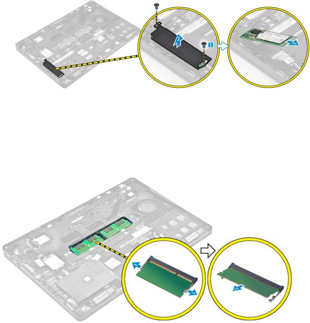
aRemove the screws that secure the SSD bracket to the SSD [1].
bRemove the SSD bracket [2].
cRemove the SSD from the computer [3].
Removing the memory module
1Follow the procedure in Before working inside your computer.
2Remove the:
abase cover
bbattery
3Pull the clips securing the memory module until the memory module pops up [1].
4Remove the memory module from the system board [2].
Installing the memory module
1Insert the memory module into the memory module socket until the clips secure the memory module.
2Install the:
abattery
bbase cover
3 Follow the procedures in After working inside your computer.
16 Disassembly and reassembly
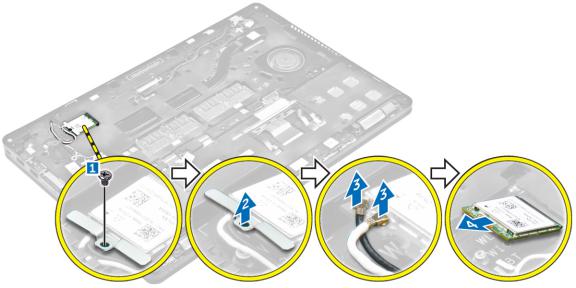
Removing the WLAN card
1Follow the procedure in Before working inside your computer.
2Remove the:
abase cover
bbattery
3 To remove the WLAN card:
aRemove the screw that secures the metal bracket to the WLAN card [1].
bRemove the metal bracket [2].
cDisconnect the WLAN cables from the connectors on the WLAN card [3].
dUnroute the WLAN cables from the routing channel.
eRemove the WLAN card from the computer [4].
Installing the WLAN card
1Insert the WLAN card into the slot on the computer.
2Route the WLAN cables through the routing channel.
3Connect the WLAN cables to the connectors on the WLAN Card.
4Place the metal bracket and tighten the screw to secure it to the computer.
5Install the:
abattery
bbase cover
6 Follow the procedure in After working inside your system.
Removing the WWAN card
1Follow the procedure in Before working inside your computer.
2Remove the:
abase cover
bbattery
3 To remove the WWAN card:
aRemove the screw that secures the WWAN card [1].
bDisconnect the WWAN cables from the connectors on the WWAN card [2].
Disassembly and reassembly |
17 |
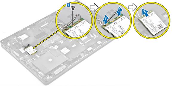
cUnroute the WWAN cables from the routing channel.
dRemove the WWAN card from the computer [3].
Installing the WWAN card
1Insert the WWAN card into the slot on the computer.
2Route the WWAN cables through the routing channel.
3Connect the WWAN cables to the connectors on the WWAN card.
4Tighten the screw to secure the WWAN card to the computer
5Install the:
abattery
bbase cover
6 Follow the procedure in After working inside your computer.
Removing the power connector port
1Follow the procedure in Before working inside your computer.
2Remove the:
abase cover
bbattery
3 To remove the power connector port:
aRemove the screws to release the metal bracket on the power connector port [1].
bLift the metal bracket from the computer [2].
cDisconnect the power connector port cable from the computer [3].
dRemove the power connector port from the computer [4].
18 Disassembly and reassembly

Installing the power connector port
1Insert the power connector port into the slot on the computer.
2Place the metal bracket on the power connector port.
3Tighten the screw to secure the power connector port to the computer.
4Route the power connector port cable through the routing channels.
5Connect the power connector port cable to the connector on the system board.
6Install the:
abattery
bbase cover
7 Follow the procedure in After working inside your computer.
Removing the keyboard
1Follow the procedure in Before working inside your computer.
2Remove the:
abase cover
bbattery
3 To remove the keyboard trim:
aDisconnect the keyboard cables from the connectors on the system board [1, 2].
bUsing a plastic scribe, lift the keyboard trim from the edges to release it from the keyboard [3, 4, 5].
Disassembly and reassembly |
19 |
Loading...