


Inspiron 3847
Owner’s Manual
Computer model: Inspiron 3847 Regulatory model: D16M Regulatory type: D16M001
Notes, Cautions, and Warnings
NOTE: A NOTE indicates important information that helps you make better use of your computer.
CAUTION: A CAUTION indicates potential damage to hardware or loss of data if instructions are not followed.
 WARNING: A WARNING indicates a potential for property damage, personal injury, or death.
____________________
© 2013 Dell Inc.
Trademarks used in this text: Dell™, the DELL logo, and Inspiron™ are trademarks of Dell Inc.
2013 - 11 |
Rev. A00 |
Contents
Before You Begin . . . . . . . . . . . . . . . . . . . . . . . . . . .
Safety Instructions. . . . . . . . . . . . . . . . . . . . . . . . . .
Recommended Tools. . . . . . . . . . . . . . . . . . . . . . . .
After Working Inside Your Computer . . . . . . . . . . .
Technical Overview . . . . . . . . . . . . . . . . . . . . . . . .
Inside View of Your Computer. . . . . . . . . . . . . . . . .
System-Board Components . . . . . . . . . . . . . . . . . .
Removing the Computer Cover . . . . . . . . . . . . . .
Procedure . . . . . . . . . . . . . . . . . . . . . . . . . . . . . .
Replacing the Computer Cover . . . . . . . . . . . . . .
Procedure . . . . . . . . . . . . . . . . . . . . . . . . . . . . . .
Postrequisites . . . . . . . . . . . . . . . . . . . . . . . . . . . .
Removing the Memory Module(s). . . . . . . . . . . . .
Prerequisites. . . . . . . . . . . . . . . . . . . . . . . . . . . . .
Procedure . . . . . . . . . . . . . . . . . . . . . . . . . . . . . .
Replacing the Memory Module(s). . . . . . . . . . . . .
Procedure . . . . . . . . . . . . . . . . . . . . . . . . . . . . . .
Postrequisites . . . . . . . . . . . . . . . . . . . . . . . . . . . .
Removing the Graphics Card . . . . . . . . . . . . . . . .
Prerequisites. . . . . . . . . . . . . . . . . . . . . . . . . . . . .
Procedure . . . . . . . . . . . . . . . . . . . . . . . . . . . . . .
Replacing the Graphics Card . . . . . . . . . . . . . . . .
Procedure . . . . . . . . . . . . . . . . . . . . . . . . . . . . . .
Postrequisites . . . . . . . . . . . . . . . . . . . . . . . . . . . .
Removing the Front Bezel . . . . . . . . . . . . . . . . . . .
Prerequisites. . . . . . . . . . . . . . . . . . . . . . . . . . . . .
Procedure . . . . . . . . . . . . . . . . . . . . . . . . . . . . . .
7
7
8
9
10
10
11
12
12
13
13
13
14
14
14
15
15
15
16
16
16
18
18
18
19
19
19
Contents | 3

Replacing the Front Bezel . . . . . . . . . . . . . . . . . . .
Procedure . . . . . . . . . . . . . . . . . . . . . . . . . . . . . .
Postrequisites . . . . . . . . . . . . . . . . . . . . . . . . . . . .
Removing the Wireless Mini-Card . . . . . . . . . . . .
Prerequisites. . . . . . . . . . . . . . . . . . . . . . . . . . . . .
Procedure . . . . . . . . . . . . . . . . . . . . . . . . . . . . . .
Replacing the Wireless Mini-Card . . . . . . . . . . . .
Procedure . . . . . . . . . . . . . . . . . . . . . . . . . . . . . .
Postrequisites . . . . . . . . . . . . . . . . . . . . . . . . . . . .
Removing the Primary Hard-Drive . . . . . . . . . . . .
Prerequisites. . . . . . . . . . . . . . . . . . . . . . . . . . . . .
Procedure . . . . . . . . . . . . . . . . . . . . . . . . . . . . . .
Replacing the Primary Hard-Drive . . . . . . . . . . . .
Procedure . . . . . . . . . . . . . . . . . . . . . . . . . . . . . .
Postrequisites . . . . . . . . . . . . . . . . . . . . . . . . . . . .
Removing the Secondary Hard-Drive. . . . . . . . . .
Prerequisites. . . . . . . . . . . . . . . . . . . . . . . . . . . . .
Procedure . . . . . . . . . . . . . . . . . . . . . . . . . . . . . .
Replacing the Secondary Hard-Drive. . . . . . . . . .
Procedure . . . . . . . . . . . . . . . . . . . . . . . . . . . . . .
Postrequisites . . . . . . . . . . . . . . . . . . . . . . . . . . . .
Removing the Optical Drive . . . . . . . . . . . . . . . . .
Prerequisites. . . . . . . . . . . . . . . . . . . . . . . . . . . . .
Procedure . . . . . . . . . . . . . . . . . . . . . . . . . . . . . .
Replacing the Optical Drive . . . . . . . . . . . . . . . . .
Procedure . . . . . . . . . . . . . . . . . . . . . . . . . . . . . .
Postrequisites . . . . . . . . . . . . . . . . . . . . . . . . . . . .
Removing the Front I/O Panel . . . . . . . . . . . . . . .
Prerequisites. . . . . . . . . . . . . . . . . . . . . . . . . . . . .
Procedure . . . . . . . . . . . . . . . . . . . . . . . . . . . . . .
20
20
20
21
21
21
22
22
22
23
23
23
25
25
25
26
26
26
28
28
28
29
29
29
31
31
31
34
34
34
4 | Contents

Replacing the Front I/O Panel. . . . . . . . . . . . . . . .
Procedure . . . . . . . . . . . . . . . . . . . . . . . . . . . . . .
Postrequisites . . . . . . . . . . . . . . . . . . . . . . . . . . . .
Removing the Power-Button Module . . . . . . . . .
Prerequisites. . . . . . . . . . . . . . . . . . . . . . . . . . . . .
Procedure . . . . . . . . . . . . . . . . . . . . . . . . . . . . . .
Replacing the Power-Button Module. . . . . . . . . .
Procedure . . . . . . . . . . . . . . . . . . . . . . . . . . . . . .
Postrequisites . . . . . . . . . . . . . . . . . . . . . . . . . . . .
Removing the Chassis Fan. . . . . . . . . . . . . . . . . .
Prerequisites. . . . . . . . . . . . . . . . . . . . . . . . . . . . .
Procedure . . . . . . . . . . . . . . . . . . . . . . . . . . . . . .
Replacing the Chassis Fan . . . . . . . . . . . . . . . . . . .
Procedure . . . . . . . . . . . . . . . . . . . . . . . . . . . . . .
Postrequisites . . . . . . . . . . . . . . . . . . . . . . . . . . . .
36
36
36
37
37
37
39
39
39
40
40
40
41
41
41
Removing the Processor Fan and
Heat Sink Assembly . . . . . . . . . . . . . . . . . . . . . . . .
Prerequisites. . . . . . . . . . . . . . . . . . . . . . . . . . . . .
Procedure . . . . . . . . . . . . . . . . . . . . . . . . . . . . . .
42
42
43
Replacing the Processor Fan and
Heat Sink Assembly . . . . . . . . . . . . . . . . . . . . . . .
Procedure . . . . . . . . . . . . . . . . . . . . . . . . . . . . . .
Postrequisites . . . . . . . . . . . . . . . . . . . . . . . . . . . .
Removing the Processor . . . . . . . . . . . . . . . . . . . .
Prerequisites. . . . . . . . . . . . . . . . . . . . . . . . . . . . .
Procedure . . . . . . . . . . . . . . . . . . . . . . . . . . . . . .
Replacing the Processor . . . . . . . . . . . . . . . . . . . .
Procedure . . . . . . . . . . . . . . . . . . . . . . . . . . . . . .
Postrequisites . . . . . . . . . . . . . . . . . . . . . . . . . . . .
Removing the Coin-Cell Battery. . . . . . . . . . . . . .
Prerequisites. . . . . . . . . . . . . . . . . . . . . . . . . . . . .
44
44
44
45
45
45
46
46
47
48
48
Contents | 5

Procedure . . . . . . . . . . . . . . . . . . . . . . . . . . . . . .
Replacing the Coin-Cell Battery . . . . . . . . . . . . . .
Procedure . . . . . . . . . . . . . . . . . . . . . . . . . . . . . .
Postrequisites . . . . . . . . . . . . . . . . . . . . . . . . . . . .
Removing the Power-Supply Unit . . . . . . . . . . . .
Prerequisites. . . . . . . . . . . . . . . . . . . . . . . . . . . . .
Procedure . . . . . . . . . . . . . . . . . . . . . . . . . . . . . .
Replacing the Power-Supply Unit. . . . . . . . . . . . .
Procedure . . . . . . . . . . . . . . . . . . . . . . . . . . . . . .
Postrequisites . . . . . . . . . . . . . . . . . . . . . . . . . . . .
Removing the System Board . . . . . . . . . . . . . . . . .
Prerequisites. . . . . . . . . . . . . . . . . . . . . . . . . . . . .
Procedure . . . . . . . . . . . . . . . . . . . . . . . . . . . . . .
Replacing the System Board . . . . . . . . . . . . . . . . .
Procedure . . . . . . . . . . . . . . . . . . . . . . . . . . . . . .
Postrequisites . . . . . . . . . . . . . . . . . . . . . . . . . . . .
Entering the Service Tag in the BIOS. . . . . . . . . . . . .
Flashing the BIOS . . . . . . . . . . . . . . . . . . . . . . . . . .
48
49
49
49
50
50
50
51
51
51
52
52
53
54
54
54
54
55
6 | Contents
Before You Begin
CAUTION: To avoid losing data, save and close all open files and exit all open programs before you turn off your computer.
1Save and close all open files and exit all open programs.
2Move your mouse pointer to the upper-right or lower-right corner of the screen to open the Charms sidebar, and then click Settings→ Power→ Shut down.
NOTE: If you are using a different operating system, see the documentation of your operating system for shut-down instructions.
3 Disconnect your computer and all attached |
devices from their electrical outlets |
4Disconnect all telephone cables, network cables, and attached devices from your computer.
5After the computer is unplugged, press and hold the power button for 5 seconds to ground the system board.
Safety Instructions
Use the following safety guidelines to protect your computer from potential damage and ensure your personal safety.
WARNING: Before working inside your computer, read the safety information that shipped with your computer. For more safety best practices, see the Regulatory Compliance home page at dell.com/regulatory_compliance.
WARNING: Disconnect all power sources before opening the computer cover or panels. After you finish working inside the computer, replace all covers, panels, and screws before connecting to the power source.
CAUTION: To avoid damaging the computer, make sure that the work surface is flat and clean.
CAUTION: To avoid damaging the components and cards, handle them by their edges and avoid touching pins and contacts.
CAUTION: Only a certified service technician is authorized to remove the computer cover and access any of the components inside the computer. See the safety instructions for complete information about safety precautions, working inside your computer, and protecting against electrostatic discharge.
CAUTION: Before touching anything inside your computer, ground yourself by touching an unpainted metal surface, such as the metal at the back of the computer. While you work, periodically touch an unpainted metal surface to dissipate static electricity, wh ich could harm internal components.
Before You Begin |
| |
7 |
CAUTION: When you disconnect a cable, pull on its connector or on its pull-tab, not on the cable itself. Some cables have connectors with locking tabs or thumb-screws that you must disengage before disconnecting the cable.
When disconnecting cables, keep them evenly aligned to avoid bending any connector pins. When connecting cables, make sure that the connectors and ports are correctly oriented and aligned.
CAUTION: To disconnect a network cable, first unplug the cable from your computer and then unplug the cable from the network device.
CAUTION: Press and eject any installed card from the media-card reader.
Recommended Tools
The procedures in this document may require the following tools:
•Phillips screwdriver
•Plastic scribe
8| Before You Begin
After Working Inside Your Computer
CAUTION: Leaving stray or loose screws inside your computer may severely damage your computer.
1Replace all screws and make sure that no stray screws remain inside your computer.
2Place the computer in an upright position.
3Connect any external devices, cables, cards, and any other part(s) you removed before working on your computer.
4Connect your computer and all attached devices to their electrical outlets.
After Working Inside Your Computer |
| |
9 |
Technical Overview
WARNING: Before working inside your computer, read the safety information that shipped with your computer and follow the steps in "Before You Begin" on page 7. After working inside your computer, follow the instructions in "After Working Inside Your Computer" on page 9. For additional safety best practices information, see the Regulatory Compliance Homepage at dell.com/regulatory_compliance.
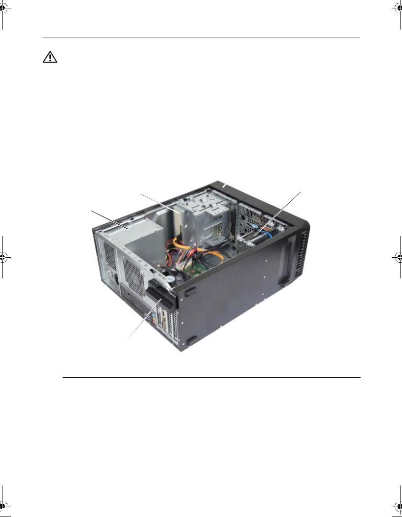
Inside View of Your Computer
|
3 |
2 |
4 |
|
1 
5
1 |
power supply |
2 |
optical drive |
|
|
|
|
3 |
front bezel |
4 |
primary hard-drive |
|
|
|
|
5 |
card retention bracket |
|
|
|
|
|
|
10 |
| |
Technical Overview |

System-Board Components
1 |
2 |
3 |
4 5 |
6 |
7 |
 8
8
 9
9  10
10
22 
21
20
19 |
|
11 |
|
 12 18
12 18 


 13
13
|
17 |
|
16 |
15 |
14 |
|
|
|
|
|
|
|
|
||
1 |
power connector (ATX12V) |
2 |
processor socket |
|
|
||
|
|
|
|
|
|
||
3 |
processor fan connector (FNCPU1) |
4 |
memory module connector |
|
|
||
|
|
|
(DIMM1) |
|
|
|
|
|
|
|
|
|
|||
5 |
memory module connector |
6 |
front panel USB connector (USBF1) |
|
|||
|
(DIMM2) |
|
|
|
|
|
|
|
|
|
|
|
|
||
7 |
main power connector (ATX1) |
8 |
CMOS reset jumper (CMCLR1) |
|
|
||
|
|
|
|
|
|||
9 |
password reset jumper (PWCLR1) |
10 |
front panel USB connector (USBF3) |
|
|||
|
|
|
|
|
|
||
11 |
SATA connector (SATA 3) |
12 |
SATA connector (SATA 2) |
|
|
||
|
|
|
|
|
|
||
13 |
power button connector (LED H1) |
14 |
SATA connector (SATA 1) |
|
|
||
|
|
|
|
|
|
||
15 |
SATA connector (SATA 0) |
16 |
battery socket (BT1) |
|
|
||
|
|
|
|
|
|
||
17 |
front panel audio connector (AUDF1) |
18 |
PCI Express x1 card slot (SLOT3) |
|
|
||
|
|
|
|
|
|
||
19 |
PCI Express x16 card slot (SLOT2) |
20 |
PCI Express x1 card slot (SLOT1) |
|
|
||
|
|
|
|
|
|
||
21 |
Mini-Card slot (MINI1) |
22 |
chassis fan connector (FANSYS2) |
|
|
||
|
|
|
|
|
|
||
|
|
|
Technical Overview |
| |
11 |
||
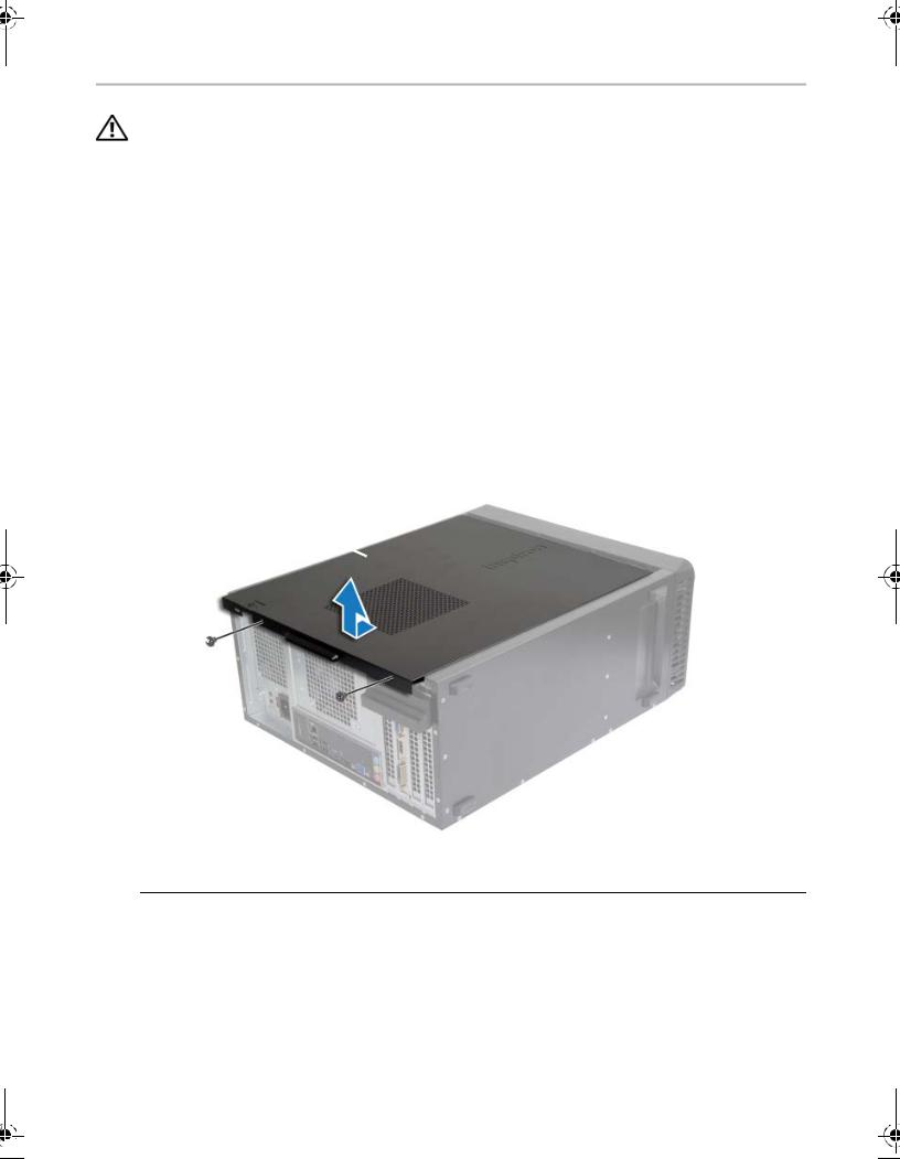
Removing the Computer Cover
WARNING: Before working inside your computer, read the safety information that shipped with your computer and follow the steps in "Before You Begin" on page 7. After working inside your computer, follow the instructions in "After Working Inside Your Computer" on page 9. For additional safety best practices information, see the Regulatory Compliance Homepage at dell.com/regulatory_compliance.
Procedure
1Place the computer on its side with the computer cover facing up.
2Using a screwdriver, remove the screws that secure the computer cover to the chassis.
3Release the computer cover by sliding it away from the front of the computer.
4Lift the cover away from the computer and set it aside.
2
1
1 |
screw |
2 |
computer cover |
|
|
|
|
12 |
| |
Removing the Computer Cover |
Replacing the Computer Cover
WARNING: Before working inside your computer, read the safety information that shipped with your computer and follow the steps in "Before You Begin" on page 7. After working inside your computer, follow the instructions in "After Working Inside Your Computer" on page 9. For additional safety best practices information, see the Regulatory Compliance Homepage at dell.com/regulatory_compliance.
Procedure
1Connect all the cables and fold the cables out of the way.
2Ensure that no tools or extra parts are left inside the computer.
3Align the tabs at the bottom of the computer cover with the slots located along the edge of the chassis.
4Press the computer cover down and slide it towards the front of the computer.
5Replace the screws that secure the computer cover to the chassis.
6Place the computer in an upright position.
Postrequisites
Follow the instructions in "After Working Inside Your Computer" on page 9.
Replacing the Computer Cover |
| |
13 |
Removing the Memory Module(s)
WARNING: Before working inside your computer, read the safety information that shipped with your computer and follow the steps in "Before You Begin" on page 7. After working inside your computer, follow the instructions in
"After Working Inside Your Computer" on page 9. For more safety best practices, see the Regulatory Compliance home page at dell.com/regulatory_compliance.
Prerequisites
Remove the computer cover. See "Removing the Computer Cover" on page 12.
Procedure
1Locate the memory-module connector on the system board. See "System-Board Components" on page 11 .
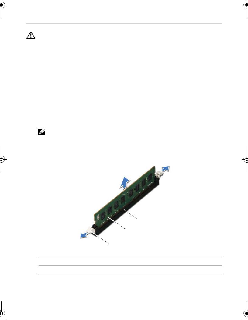
2Press out the securing clip at each end of the memory-module connector.
NOTE: If the memory module is difficult to remove, gently ease the memory module back and forth to remove it from the connector.
3Grasp the memory module and pull it upward.
 3
3
 2
2
 1
1
1 securing clips (2) |
2 memory module |
3memory-module connector
14 |
| |
Removing the Memory Module(s) |
Replacing the Memory Module(s)
WARNING: Before working inside your computer, read the safety information that shipped with your computer and follow the steps in "Before You Begin" on page 7. After working inside your computer, follow the instructions in
"After Working Inside Your Computer" on page 9. For more safety best practices, see the Regulatory Compliance home page at dell.com/regulatory_compliance.
Procedure
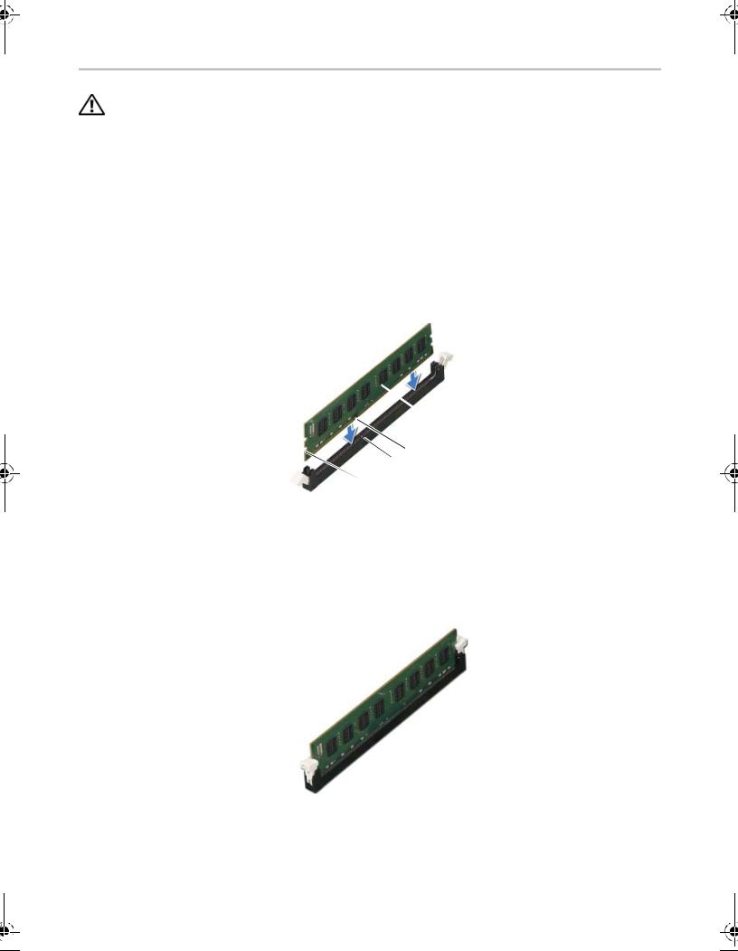
1Press out the securing clip at each end of the memory-module connector.
2Align the notch on the memory module with the tab on the memory-module connector.
|
|
|
4 |
|
|
2 3 |
|
|
|
1 |
|
|
|
|
|
1 |
cutouts (2) |
2 |
tab |
|
|
|
|
3 |
notch |
4 |
memory module |
|
|
|
|
3Insert the memory module into the memory-module connector, and press the memory module down until it snaps into position and the securing clips lock in place.
Postrequisites
Replace the computer cover. See "Rep |
lacing the Computer Cover"13. on page |
||
|
Replacing the Memory Module(s) |
| |
15 |
Removing the Graphics Card
WARNING: Before working inside your computer, read the safety information that shipped with your computer and follow the steps in "Before You Begin" on page 7. After working inside your computer, follow the instructions in
"After Working Inside Your Computer" on page 9. For more safety best practices, see the Regulatory Compliance home page at dell.com/regulatory_compliance.
Prerequisites
Remove the computer cover. See "Removing the Computer Cover" on page 12.
Procedure
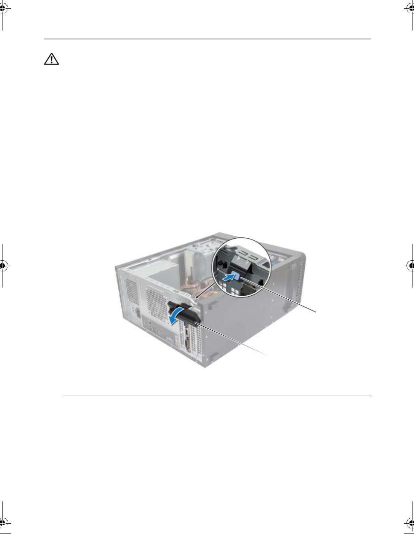
1Push the release tab to release the card retention bracket from the chassis.
 2
2
 1
1
1 |
card retention bracket |
2 |
release tab |
|
|
|
|
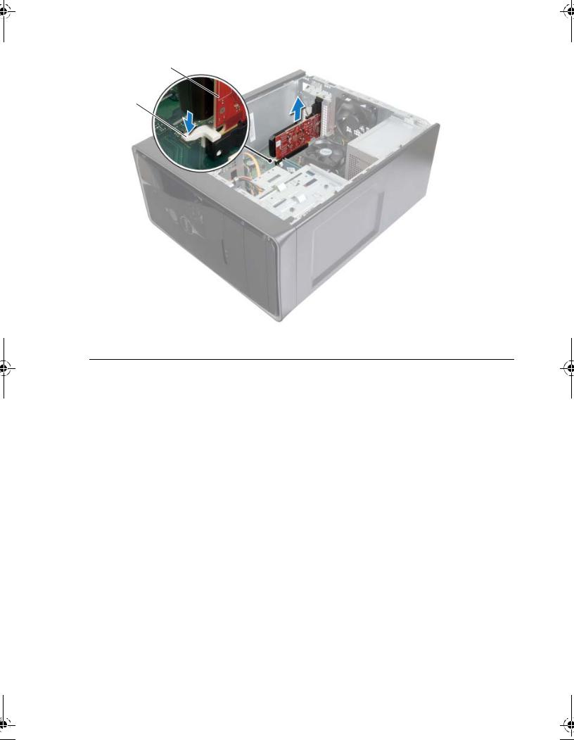
2Push the securing tab down to release the graphics card.
3Grasp the card by its top corners, and then ease it out of the connector.
16 |
| |
Removing the Graphics Card |
2
1
1 |
securing tab |
2 |
graphics card |
|
|
|
|
Removing the Graphics Card |
| |
17 |
 Loading...