


 Loading...
Latitude 5490
Owner’s Manual
Regulatory Model: P72G
Regulatory Type: P72G002
Notes, cautions, and warnings

 NOTE: A NOTE indicates important information that helps you make better use of your product.

 CAUTION: A CAUTION indicates either potential damage to hardware or loss of data and tells you how to avoid the problem.
 WARNING: A WARNING indicates a potential for property damage, personal injury, or death.
© 2018 Dell Inc. or its subsidiaries. All rights reserved. Dell, EMC, and other trademarks are trademarks of Dell Inc. or its subsidiaries. Other trademarks may be trademarks of their respective owners.
2018 - 01
Rev. A01

Contents
1 Working on your computer............................................................................................................................. |
7 |
Safety precautions............................................................................................................................................................. |
7 |
Standby power.............................................................................................................................................................. |
7 |
Bonding ......................................................................................................................................................................... |
7 |
Electrostatic discharge—ESD protection................................................................................................................. |
7 |
ESD ‚eld service kit .................................................................................................................................................... |
8 |
Transporting sensitive components........................................................................................................................... |
9 |
Before working inside your computer.............................................................................................................................. |
9 |
After working inside your computer................................................................................................................................. |
9 |
2 Removing and installing components............................................................................................................ |
10 |
Recommended tools........................................................................................................................................................ |
10 |
Screw size list.................................................................................................................................................................... |
11 |
Subscriber Identity Module(SIM) board......................................................................................................................... |
11 |
Removing the Subscriber Identi‚cation Module card............................................................................................. |
11 |
Installing the Subscriber Identi‚cation Module card............................................................................................... |
12 |
Base cover......................................................................................................................................................................... |
12 |
Removing the base cover.......................................................................................................................................... |
12 |
Installing the base cover............................................................................................................................................ |
14 |
Battery............................................................................................................................................................................... |
14 |
Lithium-ion battery precautions................................................................................................................................ |
14 |
Removing the battery................................................................................................................................................ |
15 |
Installing the battery................................................................................................................................................... |
15 |
Solid State Drive — optional .......................................................................................................................................... |
16 |
Removing the SSD card............................................................................................................................................. |
16 |
Installing the SSD card............................................................................................................................................... |
17 |
Removing the SSD frame.......................................................................................................................................... |
17 |
Installing the SSD frame............................................................................................................................................ |
18 |
Hard drive.......................................................................................................................................................................... |
18 |
Removing hard drive.................................................................................................................................................. |
18 |
Installing hard drive .................................................................................................................................................... |
19 |
Coin-cell battery............................................................................................................................................................... |
19 |
Removing the coin cell battery................................................................................................................................. |
19 |
Installing coin cell battery.......................................................................................................................................... |
20 |
WLAN card....................................................................................................................................................................... |
20 |
Removing WLAN card............................................................................................................................................... |
20 |
Installing WLAN card................................................................................................................................................. |
23 |
WWAN card – optional.................................................................................................................................................... |
23 |
Removing the WWAN card....................................................................................................................................... |
23 |
Installing the WWAN card......................................................................................................................................... |
24 |
Memory modules.............................................................................................................................................................. |
24 |
Removing the memory module................................................................................................................................ |
24 |
Installing the memory module................................................................................................................................... |
25 |
Contents 3
Keyboard lattice and Keyboard....................................................................................................................................... |
25 |
Removing keyboard lattice........................................................................................................................................ |
25 |
Installing keyboard lattice.......................................................................................................................................... |
26 |
Removing the keyboard............................................................................................................................................ |
26 |
Installing the keyboard............................................................................................................................................... |
29 |
Heat sink .......................................................................................................................................................................... |
29 |
Removing the heat sink ............................................................................................................................................ |
29 |
Installing the heat sink .............................................................................................................................................. |
30 |
System fan........................................................................................................................................................................ |
30 |
Removing the system fan......................................................................................................................................... |
30 |
Installing the system fan............................................................................................................................................ |
31 |
Power connector port..................................................................................................................................................... |
32 |
Removing the power connector port...................................................................................................................... |
32 |
Installing power connector port............................................................................................................................... |
32 |
Chassis frame................................................................................................................................................................... |
33 |
Removing the chassis frame.................................................................................................................................... |
33 |
Installing the chassis frame....................................................................................................................................... |
34 |
SmartCard module........................................................................................................................................................... |
35 |
Removing smart card reader board......................................................................................................................... |
35 |
Installing smart card reader board............................................................................................................................ |
36 |
Speaker.............................................................................................................................................................................. |
37 |
Removing the speaker............................................................................................................................................... |
37 |
Installing the speaker................................................................................................................................................. |
38 |
System board.................................................................................................................................................................... |
38 |
Removing system board............................................................................................................................................ |
38 |
Installing system board............................................................................................................................................... |
41 |
Display hinge cover.......................................................................................................................................................... |
42 |
Removing display hinge cover ................................................................................................................................. |
42 |
Installing display hinge cover ................................................................................................................................... |
43 |
Display assembly.............................................................................................................................................................. |
43 |
Removing display assembly...................................................................................................................................... |
43 |
Installing display assembly......................................................................................................................................... |
47 |
Display bezel..................................................................................................................................................................... |
48 |
Removing display bezel ............................................................................................................................................ |
48 |
Installing display bezel ............................................................................................................................................... |
49 |
Display panel..................................................................................................................................................................... |
49 |
Removing display panel ............................................................................................................................................ |
49 |
Installing display panel ............................................................................................................................................... |
51 |
Display (eDP) cable.......................................................................................................................................................... |
52 |
Removing display cable ............................................................................................................................................ |
52 |
Installing display cable .............................................................................................................................................. |
52 |
Camera.............................................................................................................................................................................. |
53 |
Removing camera...................................................................................................................................................... |
53 |
Installing camera......................................................................................................................................................... |
54 |
Display hinges................................................................................................................................................................... |
54 |
Removing display hinge ............................................................................................................................................ |
54 |
Installing display hinge .............................................................................................................................................. |
55 |
4 Contents
Display back cover assembly.......................................................................................................................................... |
55 |
Removing the display back cover assembly .......................................................................................................... |
55 |
Installing the display back cover assembly ............................................................................................................ |
56 |
Palm rest........................................................................................................................................................................... |
56 |
Removing palm rest................................................................................................................................................... |
56 |
Installing palm rest...................................................................................................................................................... |
57 |
3 Technical speci•cations............................................................................................................................... |
59 |
Processor ......................................................................................................................................................................... |
59 |
Memory ............................................................................................................................................................................ |
60 |
Storage speci‚cations..................................................................................................................................................... |
60 |
Audio speci‚cations......................................................................................................................................................... |
60 |
Video speci‚cation............................................................................................................................................................ |
61 |
Integrated.................................................................................................................................................................... |
61 |
Discrete........................................................................................................................................................................ |
61 |
Camera option .................................................................................................................................................................. |
61 |
Ports and Connectors .................................................................................................................................................... |
62 |
Contacted smart card speci‚cations............................................................................................................................. |
62 |
Display speci‚cation........................................................................................................................................................ |
62 |
Keyboard speci‚cations ................................................................................................................................................. |
64 |
Touch pad speci‚cations................................................................................................................................................. |
65 |
Battery speci‚cations...................................................................................................................................................... |
65 |
AC Adapter speci‚cations............................................................................................................................................... |
66 |
System dimensions.......................................................................................................................................................... |
67 |
Operating Conditions....................................................................................................................................................... |
67 |
4 Technology and components....................................................................................................................... |
69 |
Power adapter.................................................................................................................................................................. |
69 |
Kaby Lake — 7th Generation Intel Core processors................................................................................................... |
69 |
Kaby lake Speci‚cations............................................................................................................................................ |
70 |
Kaby Lake Refresh — 8th Generation Intel Core processors.................................................................................... |
70 |
Kaby Lake Refresh Speci‚cations............................................................................................................................. |
71 |
DDR4.................................................................................................................................................................................. |
71 |
DDR4 Details................................................................................................................................................................ |
71 |
Memory Errors............................................................................................................................................................ |
72 |
HDMI 1.4............................................................................................................................................................................ |
72 |
HDMI 1.4 Features...................................................................................................................................................... |
72 |
Advantages of HDMI................................................................................................................................................. |
73 |
HDMI 1.4............................................................................................................................................................................ |
73 |
HDMI 1.4 Features...................................................................................................................................................... |
73 |
Advantages of HDMI................................................................................................................................................. |
73 |
USB features..................................................................................................................................................................... |
74 |
USB 3.0/USB 3.1 Gen 1 (SuperSpeed USB)........................................................................................................... |
74 |
Speed........................................................................................................................................................................... |
74 |
Applications................................................................................................................................................................. |
75 |
Compatibility............................................................................................................................................................... |
75 |
Advantages of Displayport over USB Type-C......................................................................................................... |
76 |
Contents 5
USB Type-C...................................................................................................................................................................... |
76 |
Alternate Mode........................................................................................................................................................... |
76 |
USB Power Delivery................................................................................................................................................... |
76 |
5 System setup options................................................................................................................................... |
77 |
Boot Sequence................................................................................................................................................................. |
77 |
Navigation keys................................................................................................................................................................ |
78 |
System Setup overview.................................................................................................................................................. |
78 |
Accessing System Setup................................................................................................................................................. |
78 |
General screen options.................................................................................................................................................... |
78 |
System Con‚guration screen options............................................................................................................................ |
79 |
Video screen options....................................................................................................................................................... |
80 |
Security screen options................................................................................................................................................... |
81 |
Secure Boot screen options............................................................................................................................................ |
82 |
Intel Software Guard Extensions.................................................................................................................................... |
83 |
Performance screen options.......................................................................................................................................... |
83 |
Power Management screen options.............................................................................................................................. |
84 |
POST Behavior screen options...................................................................................................................................... |
85 |
Manageability................................................................................................................................................................... |
86 |
Virtualization support screen options............................................................................................................................ |
87 |
Wireless screen options................................................................................................................................................... |
87 |
Maintenance screen options........................................................................................................................................... |
87 |
6 Software...................................................................................................................................................... |
89 |
Operating system con‚gurations................................................................................................................................... |
89 |
Downloading drivers........................................................................................................................................................ |
89 |
Chipset driver............................................................................................................................................................. |
89 |
Serial IO driver............................................................................................................................................................ |
90 |
Graphics controller driver.......................................................................................................................................... |
90 |
USB drivers................................................................................................................................................................. |
90 |
Network drivers.......................................................................................................................................................... |
91 |
Realtek Audio.............................................................................................................................................................. |
91 |
Serial ATA drivers........................................................................................................................................................ |
91 |
Security drivers.......................................................................................................................................................... |
92 |
7 Troubleshooting........................................................................................................................................... |
93 |
Enhanced Pre-Boot System Assessment ePSA diagnostics...................................................................................... |
93 |
Running the ePSA Diagnostics................................................................................................................................. |
94 |
Real Time Clock reset...................................................................................................................................................... |
94 |
8 Contacting Dell............................................................................................................................................ |
95 |
6 Contents

1
Working on your computer
Topics:
•Safety precautions
•Before working inside your computer
•After working inside your computer
Safety precautions
The safety precautions chapter details the primary steps to be taken before performing any disassembly instructions.
Observe the following safety precautions before you perform any installation or break/‚x procedures involving disassembly or reassembly:
•Turn off the system and all attached peripherals.
•Disconnect the system and all attached peripherals from AC power.
•Disconnect all network cables, telephone, and telecommunications lines from the system.
•Use an ESD ‚eld service kit when working inside any notebook to avoid electrostatic discharge (ESD) damage.
•After removing any system component, carefully place the removed component on an anti-static mat.
•Wear shoes with non-conductive rubber soles to reduce the chance of getting electrocuted.
Standby power
Dell products with standby power must be unplugged before you open the case. Systems that incorporate standby power are essentially powered while turned off. The internal power enables the system to be remotely turned on (wake on LAN) and suspended into a sleep mode and has other advanced power management features.
Unplugging, pressing and holding the power button for 15 seconds should discharge residual power in the system board. notebooks.
Bonding
Bonding is a method for connecting two or more grounding conductors to the same electrical potential. This is done through the use of a ‚eld service electrostatic discharge (ESD) kit. When connecting a bonding wire, ensure that it is connected to bare metal and never to a painted or non-metal surface. The wrist strap should be secure and in full contact with your skin, and ensure that you remove all jewelry such as watches, bracelets, or rings prior to bonding yourself and the equipment.
Electrostatic discharge—ESD protection
ESD is a major concern when you handle electronic components, especially sensitive components such as expansion cards, processors, memory DIMMs, and system boards. Very slight charges can damage circuits in ways that may not be obvious, such as intermittent problems or a shortened product life span. As the industry pushes for lower power requirements and increased density, ESD protection is an increasing concern.
Due to the increased density of semiconductors used in recent Dell products, the sensitivity to static damage is now higher than in previous Dell products. For this reason, some previously approved methods of handling parts are no longer applicable.
Two recognized types of ESD damage are catastrophic and intermittent failures.
Working on your computer |
7 |
•Catastrophic – Catastrophic failures represent approximately 20 percent of ESD-related failures. The damage causes an immediate and complete loss of device functionality. An example of catastrophic failure is a memory DIMM that has received a static shock and immediately generates a "No POST/No Video" symptom with a beep code emitted for missing or nonfunctional memory.
•Intermittent – Intermittent failures represent approximately 80 percent of ESD-related failures. The high rate of intermittent failures means that most of the time when damage occurs, it is not immediately recognizable. The DIMM receives a static shock, but the tracing is merely weakened and does not immediately produce outward symptoms related to the damage. The weakened trace may take weeks or months to melt, and in the meantime may cause degradation of memory integrity, intermittent memory errors, etc.
The more difficult type of damage to recognize and troubleshoot is the intermittent (also called latent or "walking wounded") failure.
Perform the following steps to prevent ESD damage:
•Use a wired ESD wrist strap that is properly grounded. The use of wireless anti-static straps is no longer allowed; they do not provide adequate protection. Touching the chassis before handling parts does not ensure adequate ESD protection on parts with increased sensitivity to ESD damage.
•Handle all static-sensitive components in a static-safe area. If possible, use anti-static floor pads and workbench pads.
•When unpacking a static-sensitive component from its shipping carton, do not remove the component from the anti-static packing material until you are ready to install the component. Before unwrapping the anti-static packaging, ensure that you discharge static electricity from your body.
•Before transporting a static-sensitive component, place it in an anti-static container or packaging.
ESD •eld service kit
The unmonitored Field Service kit is the most commonly used service kit. Each Field Service kit includes three main components: anti-static mat, wrist strap, and bonding wire.
Components of an ESD •eld service kit
The components of an ESD ‚eld service kit are:
•Anti-Static Mat – The anti-static mat is dissipative and parts can be placed on it during service procedures. When using an anti-static mat, your wrist strap should be snug and the bonding wire should be connected to the mat and to any bare metal on the system being worked on. Once deployed properly, service parts can be removed from the ESD bag and placed directly on the mat. ESD-sensitive items are safe in your hand, on the ESD mat, in the system, or inside a bag.
•Wrist Strap and Bonding Wire – The wrist strap and bonding wire can be either directly connected between your wrist and bare metal on the hardware if the ESD mat is not required, or connected to the anti-static mat to protect hardware that is temporarily placed on the mat. The physical connection of the wrist strap and bonding wire between your skin, the ESD mat, and the hardware is known as bonding. Use only Field Service kits with a wrist strap, mat, and bonding wire. Never use wireless wrist straps. Always be aware that the internal wires of a wrist strap are prone to damage from normal wear and tear, and must be checked regularly with a wrist strap tester in order to avoid accidental ESD hardware damage. It is recommended to test the wrist strap and bonding wire at least once per week.
•ESD Wrist Strap Tester – The wires inside of an ESD strap are prone to damage over time. When using an unmonitored kit, it is a best practice to regularly test the strap prior to each service call, and at a minimum, test once per week. A wrist strap tester is the best method for doing this test. If you do not have your own wrist strap tester, check with your regional office to ‚nd out if they have one. To perform the test, plug the wrist-strap's bonding-wire into the tester while it is strapped to your wrist and push the button to test. A green LED is lit if the test is successful; a red LED is lit and an alarm sounds if the test fails.
•Insulator Elements – It is critical to keep ESD sensitive devices, such as plastic heat sink casings, away from internal parts that are insulators and often highly charged.
•Working Environment – Before deploying the ESD Field Service kit, assess the situation at the customer location. For example, deploying the kit for a server environment is different than for a desktop or portable environment. Servers are typically installed in a rack within a data center; desktops or portables are typically placed on office desks or cubicles. Always look for a large open flat work area that is free of clutter and large enough to deploy the ESD kit with additional space to accommodate the type of system that is being repaired. The workspace should also be free of insulators that can cause an ESD event. On the work area, insulators such as Styrofoam and other plastics should always be moved at least 12 inches or 30 centimeters away from sensitive parts before physically handling any hardware components
•ESD Packaging – All ESD-sensitive devices must be shipped and received in static-safe packaging. Metal, static-shielded bags are preferred. However, you should always return the damaged part using the same ESD bag and packaging that the new part arrived in. The ESD bag should be folded over and taped shut and all the same foam packing material should be used in the original box that the new part arrived in. ESD-sensitive devices should be removed from packaging only at an ESD-protected work surface, and parts should never be placed on top of the ESD bag because only the inside of the bag is shielded. Always place parts in your hand, on the ESD mat, in the system, or inside an anti-static bag.
8 Working on your computer

•Transporting Sensitive Components – When transporting ESD sensitive components such as replacement parts or parts to be returned to Dell, it is critical to place these parts in anti-static bags for safe transport.
ESD protection summary
It is recommended that all ‚eld service technicians use the traditional wired ESD grounding wrist strap and protective anti-static mat at all times when servicing Dell products. In addition, it is critical that technicians keep sensitive parts separate from all insulator parts while performing service and that they use anti-static bags for transporting sensitive components.
Transporting sensitive components
When transporting ESD sensitive components such as replacement parts or parts to be returned to Dell, it is critical to place these parts in anti-static bags for safe transport.
Before working inside your computer
1Ensure that your work surface is flat and clean to prevent the computer cover from being scratched.
2Turn off your computer.
3If the computer is connected to a docking device (docked), undock it.
4Disconnect all network cables from the computer (if available).
CAUTION: If your computer has an RJ45 port, disconnect the network cable by •rst unplugging the cable from your computer.
5Disconnect your computer and all attached devices from their electrical outlets.
6Open the display.
7Press and hold the power button for few seconds, to ground the system board.

 CAUTION: To guard against electrical shock unplug your computer from the electrical outlet before performing Step # 8.
CAUTION: To avoid electrostatic discharge, ground yourself by using a wrist grounding strap or by periodically touching an unpainted metal surface at the same time as touching a connector on the back of the computer.
8 Remove any installed ExpressCards or Smart Cards from the appropriate slots.
After working inside your computer
After you complete any replacement procedure, ensure that you connect any external devices, cards, and cables before turning on your computer.
CAUTION: To avoid damage to the computer, use only the battery designed for this particular Dell computer. Do not use batteries designed for other Dell computers.
1Connect any external devices, such as a port replicator or media base, and replace any cards, such as an ExpressCard.
2Connect any telephone or network cables to your computer.
CAUTION: To connect a network cable, •rst plug the cable into the network device and then plug it into the computer.
3Connect your computer and all attached devices to their electrical outlets.
4Turn on your computer.
Working on your computer |
9 |

2
Removing and installing components
Topics:
•Recommended tools
•Screw size list
•Subscriber Identity Module(SIM) board
•Base cover
•Battery
•Solid State Drive — optional
•Hard drive
•Coin-cell battery
•WLAN card
•WWAN card – optional
•Memory modules
•Keyboard lattice and Keyboard
•Heat sink
•System fan
•Power connector port
•Chassis frame
•SmartCard module
•Speaker
•System board
•Display hinge cover
•Display assembly
•Display bezel
•Display panel
•Display (eDP) cable
•Camera
•Display hinges
•Display back cover assembly
•Palm rest
Recommended tools
The procedures in this document require the following tools:
•Phillips #0 screwdriver
•Phillips #1 screwdriver
•Plastic scribe

 NOTE: The #0 screw driver is for screws 0-1 and the #1 screw driver is for screws 2-4
10 Removing and installing components
Screw size list
Table 1. Latitude 5490 screw size list
Component |
M2x3 (Thin |
M2.0x5 |
M2.0x2.0 |
M2x6 |
M2x2. |
M2.0x2.5 |
M2.5x3 |
|
head) |
7 |
|||||||
|
|
|
|
|
|
|||
|
|
|
|
|
|
|
|
|
Base cover |
|
|
|
8 |
|
|
|
|
|
|
|
|
|
|
|
|
|
Battery |
|
|
|
1 |
|
|
|
|
|
|
|
|
|
|
|
|
|
Heatsink |
4 |
|
|
|
|
|
|
|
|
|
|
|
|
|
|
|
|
WLAN |
1 |
|
|
|
|
|
|
|
|
|
|
|
|
|
|
|
|
SSD card |
1 |
|
|
|
|
|
|
|
|
|
|
|
|
|
|
|
|
Keyboard |
|
|
|
|
|
5 |
|
|
|
|
|
|
|
|
|
|
|
Display assembly |
|
4 |
|
|
|
|
|
|
|
|
|
|
|
|
|
|
|
Display panel |
4 |
|
|
|
|
|
|
|
|
|
|
|
|
|
|
|
|
Power connector port |
2 |
|
|
|
|
|
|
|
|
|
|
|
|
|
|
|
|
Palmrest |
2 |
|
|
|
|
|
|
|
|
|
|
|
|
|
|
|
|
LED board |
|
|
1 |
|
|
|
|
|
|
|
|
|
|
|
|
|
|
System board |
4 |
|
|
|
|
|
|
|
|
|
|
|
|
|
|
|
|
Type-C USB bracket |
|
2 |
|
|
|
|
|
|
|
|
|
|
|
|
|
|
|
Display hinge cover |
2 |
|
|
|
|
|
|
|
|
|
|
|
|
|
|
|
|
Display hinge |
|
|
|
|
|
|
6 |
|
|
|
|
|
|
|
|
|
|
Hard drive |
|
|
|
|
4 |
|
|
|
|
|
|
|
|
|
|
|
|
Chassis frame |
5 |
8 |
|
|
|
|
|
|
|
|
|
|
|
|
|
|
|
Touchpad panel(button) |
2 |
|
|
|
|
|
|
|
|
|
|
|
|
|
|
|
|
Smart card module |
2 |
|
|
|
|
|
|
|
|
|
|
|
|
|
|
|
|
SSD frame |
1 |
|
|
|
|
|
|
|
|
|
|
|
|
|
|
|
|
WWAN frame |
1 |
|
|
|
|
|
|
|
|
|
|
|
|
|
|
|
Subscriber Identity Module(SIM) board
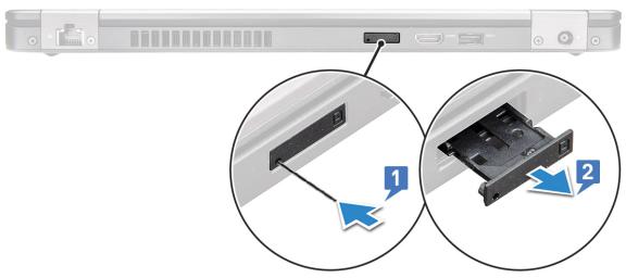
Removing the Subscriber Identi•cation Module card
CAUTION: Removing the SIM card when the computer is on may cause data loss or damage the card. Ensure your computer is turned oƒ or the network connections are disabled.
1Insert a paperclip or a SIM card removal tool into the pinhole on the SIM card tray [1].
2Pull the SIM card tray to remove it [2].
3Remove the SIM card from the SIM card tray.
Removing and installing components |
11 |
4 Push the SIM card tray into the slot until it clicks into place.
Installing the Subscriber Identi•cation Module card
1Insert a paperclip or a SIM card removal tool into the pinhole [1].
2Pull the SIM card tray to remove it [2].
3Place the SIM card on the SIM card tray.
4Push the SIM card tray into the slot until it clicks into place .
Base cover
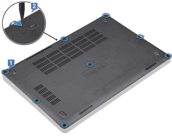
Removing the base cover
1Follow the procedure in Before working inside your computer.
2To remove the base cover:
aLoosen the 8 (M2.0x6) captive screws that secure the base cover to the system [1].
bPry the base cover from the recess at the top edge [2] and continue prying throughout the outer sides of the base cover in clockwise direction to release the base cover.

 NOTE: Use a plastic scribe to pry the base cover from the edges.
12 Removing and installing components
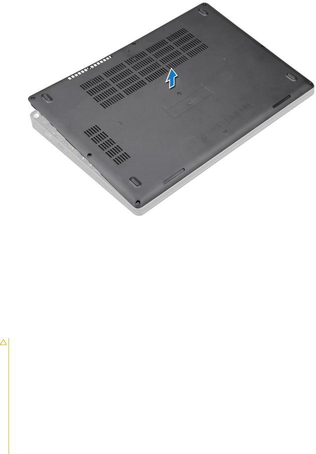
c Lift the base cover from the system.
Removing and installing components |
13 |
Installing the base cover
1Place the base cover to align with the screw holders on the system.
2Tighten the 8 (M2.0x6) captive screws to secure the base cover to the system.
3Follow the procedure in After working inside your computer.
Battery
Lithium-ion battery precautions
CAUTION:
•Exercise caution when handling Lithium-ion batteries.
•Discharge the battery as much as possible before removing it from the system. This can be done by disconnecting the AC adapter from the system to allow the battery to drain.
•Do not crush, drop, mutilate, or penetrate the battery with foreign objects.
•Do not expose the battery to high temperatures, or disassemble battery packs and cells.
•Do not apply pressure to the surface of the battery.
•Do not bend the battery.
•Do not use tools of any kind to pry on or against the battery.
•If a battery gets stuck in a device as a result of swelling, do not try to free it as puncturing, bending, or crushing a Lithium-ion battery can be dangerous. In such an instance, the entire system should be replaced. Contact https://www.dell.com/support for assistance and further instructions.
•Always purchase genuine batteries from https://www.dell.com or authorized Dell partners and re-sellers.
14 Removing and installing components
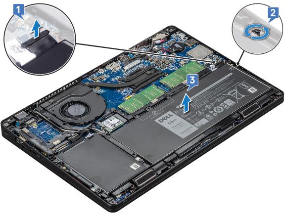
Removing the battery
1Follow the procedure in Before working inside your computer.
2Remove the base cover.
3To remove the battery:
aDisconnect the battery cable from the connector on the system board [1] and unroute the cable from the routing channel.
bLoosen the M2x6 captive screw that secures the battery to the system [2].
cLift the battery away from the system [3].
Installing the battery
1Insert the battery into the slot on the system.
2Route the battery cable through the routing channel.
3Tighten the M2x6 captive screw to secure the battery to the system.
4Connect the battery cable to the connector on the system board.
5Install the base cover.
6Follow the procedure in After working inside your computer.
Removing and installing components |
15 |
Solid State Drive — optional
Removing the SSD card

 NOTE: The following steps are applicable for SATA M.2 2280 and PCIe M.2 2280
1Follow the procedure in Before working inside your computer.
2Remove the :
abase cover
bbattery
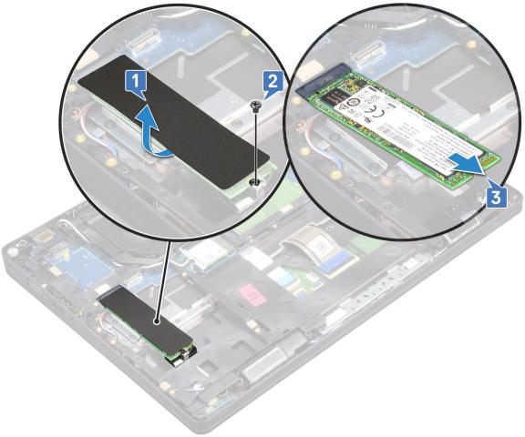
3 To remove the Solid State Drive (SSD) card:
a Peel the adhesive mylar shield that secures the SSD card [1].

 NOTE: Remove the adhesive mylar carefully so that it can be reused on the replacement SSD.
bRemove the M2x3 screw that secures the SSD to the system [2].
cSlide and lift the SSD from the system [3].
16 Removing and installing components
Installing the SSD card

 NOTE: The following procedure applies for SATA M.2 2280 and PCIe M.2 2280
1Insert the SSD card into the connector on the system.
2Replace the M2*3 screw that secures the SSD card to the system.
3Place the Mylar shield over the SSD.
4Install the :
abattery
bbase cover
5 Follow the procedure in After working inside your computer.
Removing the SSD frame
1Follow the procedure in Before working inside your computer.
2Remove the:
abase cover
bbattery
cSSD card
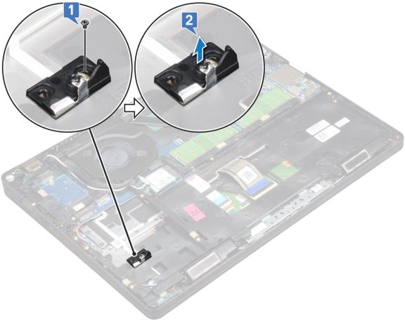
3 To remove the SSD frame:
aRemove the M2x3 screw that secures the SSD frame to the system [1].
bLift the SSD frame from the system [2].
Removing and installing components |
17 |
Installing the SSD frame
1Place the SSD frame into the slot in the system.
2Replace the M2x3 screw that secures the SSD frame to the system.
3Install the:
aSSD card
bbattery
cbase cover
4 Follow the procedure in After working inside your computer.
Hard drive
Removing hard drive
1Follow the procedure in Before working inside your computer.
2Remove the :
abase cover
bbattery
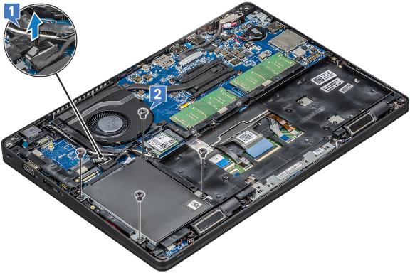
3 To remove the hard drive:
aDisconnect the hard drive cable from the connector on the system board [1].
bRemove the four (M2 x 2.7) screws that secure the hard drive to the system [2].
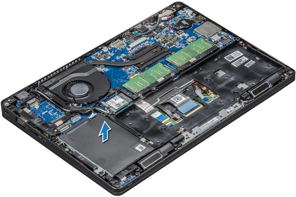
c Lift the hard drive from the system.
18 Removing and installing components
Installing hard drive
1Insert the hard drive into the slot on the system.
2Replace the four (M2 x 2.7) screws to secure the hard drive to the system.
3Connect the hard drive cable to the connector on the system board.
4Install the :
abattery
bbase cover
5 Follow the procedures in After working inside your system.
Coin-cell battery
Removing the coin cell battery
1Follow the procedure in Before working inside your computer.
2Remove the :
abase cover
bbattery
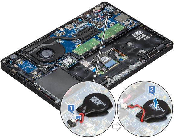
3 To remove the coin cell battery:
aDisconnect the coin cell battery cable from the connector on the system board [1].
bLift the coin cell battery to release from the adhesive and lift it away from the system board [2].
Removing and installing components |
19 |
Installing coin cell battery
1Affix the coin cell battery on the system board.
2Connect the coin cell battery cable to the connector on the system board.
3Install the :
abattery
bbase cover
4 Follow the procedure in After working inside your computer.
WLAN card
Removing WLAN card
1Follow the procedure in Before working inside your computer.
2Remove the :
abase cover
bbattery
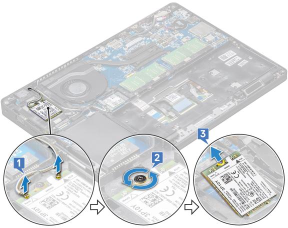
3 To remove the WLAN card:
aRemove the M2x3 screw that secures the WLAN card bracket to the system [1].
bRemove the WLAN card bracket that secures the WLAN antenna cables [2].
cDisconnect the WLAN antenna cables from the connectors on the WLAN card [3].
dLift the WLAN card away the connector as shown in the ‚gure [4].
20 Removing and installing components
CAUTION: There is an adhesive pad on the system board or chassis frame which helps secure the wireless card in place. When removing the wireless card from the system, make sure the adhesive pad stays on the system board/ chassis frame during the prying process. If the adhesive pad is removed from the system along with the wireless card, adhere it back to the system.
Removing and installing components |
21 |

22 Removing and installing components
Installing WLAN card
1Insert the WLAN card into the connector on the system board.
2Connect the WLAN antenna cables to the connectors on the WLAN card.
3Place the WLAN card bracket to secure the WLAN cables.
4Replace the M2x3 screw to secure the WLAN card to the system.
5Install the :
abattery
bbase cover
6 Follow the procedure in After working inside your computer.
WWAN card – optional
This is optional as the system might not ship with WWAN card.
Removing the WWAN card
1Follow the procedure in Before working inside your computer.
2Remove the :
abase cover
bbattery
3 To remove the WWAN card:
aDisconnect the WWAN antenna cables from the connectors on the WWAN card [1].
bRemove the M2x3 screw that secures the WWAN card to the system [2]
cSlide and lift the WWAN card from the system [3].
Removing and installing components |
23 |
Installing the WWAN card
1Insert the WWAN card into the slot on the system.
2Connect the WWAN antenna cables to the connectors on the WWAN card.
3Replace the screw (M2X3) to secure the WWAN card to the computer.
4Install the :
abattery
bbase cover
5 Follow the procedure in After working inside your computer.
Memory modules
Removing the memory module
1Follow the procedure in Before working inside your computer.
2Remove the :
abase cover
bbattery
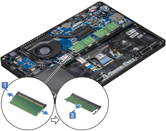
3 To remove the memory module:
aPry the clips securing the memory module until the memory module pops-up [1].
bLift the memory module from the connector [2].
24 Removing and installing components
Installing the memory module
1Insert the memory module into the memory connector at a 30 degree angle until the contacts are fully seated into the slot. Then, press the module until the clips secure the memory module.
2Install the :
abattery
bbase cover
3 Follow the procedure in After working inside your computer.
Keyboard lattice and Keyboard
Removing keyboard lattice
1Follow the procedure in Before working inside your computer.
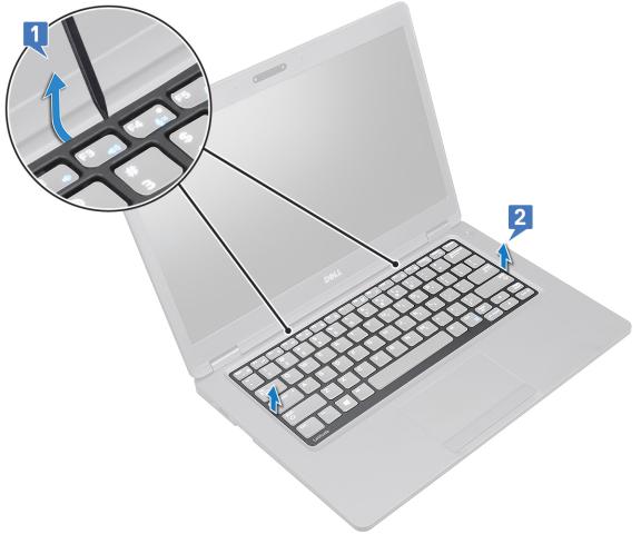
2Pry the keyboard lattice from one of the recess points [1] and lift the lattice from the system [2].

 NOTE: Gently pull or lift keyboard lattice in clockwise or anticlockwise direction to avoid breakage.
Removing and installing components |
25 |
Installing keyboard lattice
1Place the keyboard lattice on the keyboard and press along the edges and in between the rows of keys until the lattice clicks in place.
2Follow the procedure in After working inside your computer.
Removing the keyboard
1Follow the procedure in Before working inside your computer.
2Remove the:
abase cover
bbattery
ckeyboard lattice
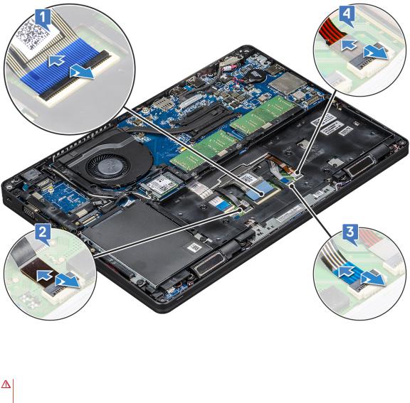
3 To remove the keyboard:
aLift the latch and disconnect the keyboard cable from the connector on the system.
bLift the latch and disconnect the keyboard backlight cables from the connectors on the system [2,3,4].

 NOTE: Number of cables to disconnect is based on the keyboard type.
26 Removing and installing components
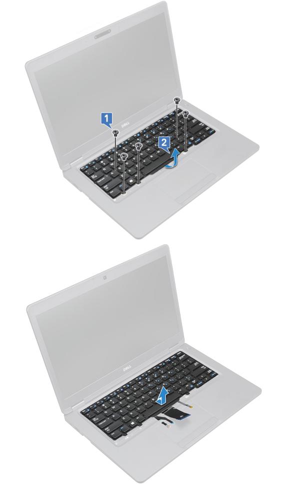
cTurn over the system and open the laptop in front view mode.
dRemove the ‚ve (M2x2.5) screws that secure the keyboard to the system [1].
eFlip the keyboard from the bottom and lift it from the system along with the keyboard cable and the keyboard back light cable [2].
WARNING: Gently pull the keyboard cable and the keyboard back light cables routed beneath the chassis frame to avoid damaging the cables.
Removing and installing components |
27 |
28 Removing and installing components

Installing the keyboard
1Hold the keyboard and route the keyboard cable and the keyboard backlight cables through the palmrest in the system.
2Align the keyboard with the screw holders on the system.
3Replace the ‚ve (M2x2.5) screws to secure the keyboard to the system.
4Turn the system over and connect the keyboard cable and the keyboard backlight cable to the connector in the system.
NOTE: When reinstalling the chassis frame ensure the keyboard cables are NOT under the lattice , but run through the opening in the frame before connecting them to system board.
5 Install the:
akeyboard lattice
bbattery
cbase cover
6 Follow the procedure in After working inside your computer.
Heat sink
Removing the heat sink

 NOTE: This procedure is only for the UMA model.
1Follow the procedure in Before working inside your computer.
2Remove the :
abase cover
bbattery
3 To remove the heat sink :
a Remove the four (M2x3) screws that secure the heat sink on the system board [1].
NOTE:
• Remove the heat sink screws in sequential order as indicated on the heat-sink. b Lift the heat sink from the system [2].
Removing and installing components |
29 |
Loading...