


 Loading...
Dell Latitude 5480
Owner's Manual
Regulatory Model: P72G
Regulatory Type: P72G001
Notes, cautions, and warnings

 NOTE: A NOTE indicates important information that helps you make better use of your product.

 CAUTION: A CAUTION indicates either potential damage to hardware or loss of data and tells you how to avoid the problem.
 WARNING: A WARNING indicates a potential for property damage, personal injury, or death.
© 2017 Dell Inc. or its subsidiaries. All rights reserved. Dell, EMC, and other trademarks are trademarks of Dell Inc. or its subsidiaries. Other trademarks may be trademarks of their respective owners.
2017 - 01
Rev. A00

Contents
1 Working on your computer............................................................................................................................. |
8 |
Safety instructions............................................................................................................................................................. |
8 |
Before working inside your computer.............................................................................................................................. |
8 |
After working inside your computer................................................................................................................................. |
9 |
Turning o• your computer................................................................................................................................................ |
9 |
Turning o• your computer — Windows 10............................................................................................................... |
9 |
Turning o• your computer — Windows 7................................................................................................................ |
9 |
2 Chassis view................................................................................................................................................. |
10 |
System front view............................................................................................................................................................ |
10 |
System back view.............................................................................................................................................................. |
11 |
System side view............................................................................................................................................................... |
11 |
System side view.............................................................................................................................................................. |
12 |
System top view............................................................................................................................................................... |
13 |
3 Removing and installing components............................................................................................................ |
14 |
Recommended tools......................................................................................................................................................... |
14 |
Subscriber Identity Module(SIM) board........................................................................................................................ |
14 |
Installing the Subscriber Identiƒcation Module (SIM) card................................................................................... |
14 |
Removing the Subscriber Identiƒcation Module (SIM) card................................................................................. |
14 |
Base cover......................................................................................................................................................................... |
15 |
Removing base cover................................................................................................................................................. |
15 |
Installing base cover................................................................................................................................................... |
15 |
Battery............................................................................................................................................................................... |
16 |
Removing battery....................................................................................................................................................... |
16 |
Installing battery.......................................................................................................................................................... |
16 |
Solid State Drive (SSD).................................................................................................................................................... |
17 |
Removing optional M.2 Solid State Drive (SSD)..................................................................................................... |
17 |
Installing optional M.2 SSD........................................................................................................................................ |
18 |
Hard drive.......................................................................................................................................................................... |
18 |
Removing hard drive assembly................................................................................................................................. |
18 |
Installing hard drive assembly.................................................................................................................................... |
19 |
Coin cell battery................................................................................................................................................................ |
19 |
Removing the coin cell battery................................................................................................................................. |
19 |
Installing coin cell battery.......................................................................................................................................... |
20 |
WLAN card....................................................................................................................................................................... |
20 |
Removing WLAN card............................................................................................................................................... |
20 |
Installing WLAN card.................................................................................................................................................. |
21 |
Memory module................................................................................................................................................................ |
21 |
Removing memory module........................................................................................................................................ |
21 |
Installing memory module.......................................................................................................................................... |
22 |
Keyboard........................................................................................................................................................................... |
22 |
Removing keyboard trim........................................................................................................................................... |
22 |
Contents |
3 |

|
Installing keyboard trim.............................................................................................................................................. |
23 |
|
Removing keyboard................................................................................................................................................... |
23 |
|
Installing keyboard...................................................................................................................................................... |
24 |
|
Heat sink........................................................................................................................................................................... |
24 |
|
Removing heatsink .................................................................................................................................................... |
24 |
|
Installing heat sink ..................................................................................................................................................... |
25 |
|
System fan........................................................................................................................................................................ |
25 |
|
Removing the system fan......................................................................................................................................... |
25 |
|
Installing the system fan............................................................................................................................................ |
26 |
|
Power connector port..................................................................................................................................................... |
26 |
|
Removing power connector port............................................................................................................................. |
26 |
|
Installing power connector port................................................................................................................................ |
27 |
|
Chassis frame................................................................................................................................................................... |
27 |
|
Removing chassis frame............................................................................................................................................ |
27 |
|
Installing chassis frame.............................................................................................................................................. |
29 |
|
System board.................................................................................................................................................................... |
29 |
|
Removing system board............................................................................................................................................ |
29 |
|
Installing system board.............................................................................................................................................. |
32 |
|
Touchpad buttons board................................................................................................................................................. |
33 |
|
Removing touchpad panel........................................................................................................................................ |
33 |
|
Installing touchpad panel........................................................................................................................................... |
33 |
|
SmartCard module........................................................................................................................................................... |
34 |
|
Removing smart card reader board......................................................................................................................... |
34 |
|
Installing smart card reader board............................................................................................................................ |
35 |
|
LED board......................................................................................................................................................................... |
35 |
|
Removing LED board................................................................................................................................................. |
35 |
|
Installing LED board................................................................................................................................................... |
36 |
|
Speaker............................................................................................................................................................................. |
36 |
|
Removing speaker..................................................................................................................................................... |
36 |
|
Installing speaker........................................................................................................................................................ |
37 |
|
Display assembly.............................................................................................................................................................. |
38 |
|
Removing display assembly...................................................................................................................................... |
38 |
|
Installing display assembly.......................................................................................................................................... |
41 |
|
Display bezel..................................................................................................................................................................... |
42 |
|
Removing display bezel............................................................................................................................................. |
42 |
|
Installing display bezel................................................................................................................................................ |
42 |
|
Display hinge cover.......................................................................................................................................................... |
43 |
|
Removing display hinge cover.................................................................................................................................. |
43 |
|
Installing display hinge cover.................................................................................................................................... |
43 |
|
Display hinges................................................................................................................................................................... |
44 |
|
Removing display hinge............................................................................................................................................. |
44 |
|
Installing display hinge............................................................................................................................................... |
45 |
|
Display panel..................................................................................................................................................................... |
45 |
|
Removing display panel............................................................................................................................................. |
45 |
|
Installing display panel................................................................................................................................................ |
47 |
|
eDP cable.......................................................................................................................................................................... |
48 |
|
Removing eDP cable................................................................................................................................................. |
48 |
4 |
Contents |
|

Installing eDP cable.................................................................................................................................................... |
48 |
Camera.............................................................................................................................................................................. |
49 |
Removing camera...................................................................................................................................................... |
49 |
Installing camera........................................................................................................................................................ |
50 |
Palm rest........................................................................................................................................................................... |
50 |
Removing palm rest................................................................................................................................................... |
50 |
Installing palmrest....................................................................................................................................................... |
51 |
4 Technology and components........................................................................................................................ |
52 |
Power adapter.................................................................................................................................................................. |
52 |
Processors........................................................................................................................................................................ |
52 |
Skylake processor...................................................................................................................................................... |
52 |
Kaby Lake — 7th Generation Intel Core processors............................................................................................. |
53 |
Identifying processors in Windows 10..................................................................................................................... |
54 |
Verifying the processor usage in Task Manager.................................................................................................... |
54 |
Verifying the processor usage in Resource Monitor.............................................................................................. |
54 |
Chipsets............................................................................................................................................................................ |
55 |
Intel chipset drivers................................................................................................................................................... |
55 |
Downloading the chipset driver............................................................................................................................... |
56 |
Identifying the chipset in Device Manager on Windows 10.................................................................................. |
56 |
Graphic options................................................................................................................................................................ |
56 |
Intel HD Graphics drivers.......................................................................................................................................... |
57 |
Downloading drivers.................................................................................................................................................. |
57 |
Display options.................................................................................................................................................................. |
57 |
Identifying the display adapter.................................................................................................................................. |
57 |
Changing the screen resolution............................................................................................................................... |
58 |
Rotating the display................................................................................................................................................... |
58 |
Adjusting brightness in Windows 10........................................................................................................................ |
58 |
Cleaning the display................................................................................................................................................... |
59 |
Using touch screen in Windows 10.......................................................................................................................... |
59 |
Connecting to external display devices................................................................................................................... |
59 |
Realtek ALC3246 Waves MaxxAudio Pro controller.................................................................................................... |
59 |
Downloading the audio driver................................................................................................................................... |
60 |
Identifying the audio controller in Windows 10....................................................................................................... |
60 |
Changing the audio settings..................................................................................................................................... |
60 |
WLAN cards..................................................................................................................................................................... |
60 |
Secure Boot screen options...................................................................................................................................... |
61 |
Hard drive options............................................................................................................................................................ |
61 |
Identifying the hard drive in Windows 10................................................................................................................. |
61 |
Identifying the hard drive in the BIOS...................................................................................................................... |
61 |
Camera features............................................................................................................................................................... |
62 |
Identifying the camera in Device Manager on Windows 10.................................................................................. |
62 |
Starting the camera................................................................................................................................................... |
62 |
Starting the camera application............................................................................................................................... |
62 |
Memory features.............................................................................................................................................................. |
63 |
Verifying system memory in Windows 10................................................................................................................ |
63 |
Verifying system memory in system setup (BIOS)................................................................................................ |
64 |
Contents |
5 |

|
Testing memory using ePSA..................................................................................................................................... |
64 |
|
Realtek HD audio drivers................................................................................................................................................. |
64 |
|
Thunderbolt over Type-C................................................................................................................................................ |
64 |
|
Thunderbolt 3 over Type-C...................................................................................................................................... |
65 |
|
Key Features of Thunderbolt 3 over USB Type-C ................................................................................................ |
65 |
|
Thunderbolt Icons...................................................................................................................................................... |
66 |
|
5 System setup options.................................................................................................................................. |
67 |
|
Boot Sequence................................................................................................................................................................. |
67 |
|
Navigation keys................................................................................................................................................................ |
68 |
|
System Setup overview.................................................................................................................................................. |
68 |
|
Accessing System Setup................................................................................................................................................ |
68 |
|
General screen options.................................................................................................................................................... |
68 |
|
System Conƒguration screen options........................................................................................................................... |
69 |
|
Video screen options........................................................................................................................................................ |
71 |
|
Security screen options.................................................................................................................................................... |
71 |
|
Secure Boot screen options............................................................................................................................................ |
73 |
|
Intel Software Guard Extensions.................................................................................................................................... |
73 |
|
Performance screen options........................................................................................................................................... |
74 |
|
Power Management screen options.............................................................................................................................. |
74 |
|
POST Behavior screen options...................................................................................................................................... |
76 |
|
Virtualization support screen options............................................................................................................................ |
77 |
|
Wireless screen options................................................................................................................................................... |
77 |
|
Maintenance screen options........................................................................................................................................... |
78 |
|
System Log screen options............................................................................................................................................. |
78 |
|
Updating the BIOS in Windows ..................................................................................................................................... |
78 |
|
System and setup password........................................................................................................................................... |
79 |
|
Assigning a system password and setup password............................................................................................... |
79 |
|
Deleting or changing an existing system and/or setup password....................................................................... |
80 |
|
6 Technical specifications................................................................................................................................ |
81 |
|
System speciƒcations....................................................................................................................................................... |
81 |
|
Processor speciƒcations................................................................................................................................................. |
82 |
|
Memory speciƒcations.................................................................................................................................................... |
82 |
|
Storage speciƒcations..................................................................................................................................................... |
82 |
|
Audio speciƒcations......................................................................................................................................................... |
82 |
|
Video speciƒcations......................................................................................................................................................... |
83 |
|
Camera speciƒcations..................................................................................................................................................... |
83 |
|
Communication speciƒcations........................................................................................................................................ |
83 |
|
Port and connector speciƒcations................................................................................................................................. |
84 |
|
Contactless smart card speciƒcations.......................................................................................................................... |
84 |
|
Display speciƒcations....................................................................................................................................................... |
84 |
|
Keyboard speciƒcations.................................................................................................................................................. |
85 |
|
Touchpad speciƒcations.................................................................................................................................................. |
85 |
|
Battery speciƒcations...................................................................................................................................................... |
86 |
|
AC Adapter speciƒcations............................................................................................................................................... |
86 |
|
Physical speciƒcations..................................................................................................................................................... |
87 |
6 |
Contents |
|

Environmental speciƒcations.......................................................................................................................................... |
87 |
7 Diagnostics.................................................................................................................................................. |
88 |
Enhanced Pre-Boot System Assessment (ePSA) diagnostics................................................................................... |
88 |
Device status lights.......................................................................................................................................................... |
89 |
Battery status lights........................................................................................................................................................ |
90 |
8 Troubleshooting............................................................................................................................................ |
91 |
Enhanced Pre-Boot System Assessment (ePSA) diagnostics.................................................................................... |
91 |
Running the ePSA diagnostics.................................................................................................................................. |
91 |
Real Time Clock (RTC) reset.......................................................................................................................................... |
91 |
9 Contacting Dell............................................................................................................................................ |
93 |
Contents 7

1
Working on your computer
Safety instructions
Use the following safety guidelines to protect your computer from potential damage and to ensure your personal safety. Unless otherwise noted, each procedure included in this document assumes that the following conditions exist:
•You have read the safety information that shipped with your computer.
•A component can be replaced or, if purchased separately, installed by performing the removal procedure in reverse order.
WARNING: Disconnect all power sources before opening the computer cover or panels. After you finish working inside the computer, replace all covers, panels, and screws before connecting to the power source.
WARNING: Before working inside your computer, read the safety information that shipped with your computer. For additional safety best practices information, see the Regulatory Compliance Homepage at www.dell.com/regulatory_compliance
CAUTION: Many repairs may only be done by a certified service technician. You should only perform troubleshooting and simple repairs as authorized in your product documentation, or as directed by the online or telephone service and support team. Damage due to servicing that is not authorized by Dell is not covered by your warranty. Read and follow the safety instructions that came with the product.
CAUTION: To avoid electrostatic discharge, ground yourself by using a wrist grounding strap or by periodically touching an unpainted metal surface at the same time as touching a connector on the back of the computer.
CAUTION: Handle components and cards with care. Do not touch the components or contacts on a card. Hold a card by its edges or by its metal mounting bracket. Hold a component such as a processor by its edges, not by its pins.
CAUTION: When you disconnect a cable, pull on its connector or on its pull-tab, not on the cable itself. Some cables have connectors with locking tabs; if you are disconnecting this type of cable, press in on the locking tabs before you disconnect the cable. As you pull connectors apart, keep them evenly aligned to avoid bending any connector pins. Also, before you connect a cable, ensure that both connectors are correctly oriented and aligned.

 NOTE: The color of your computer and certain components may appear differently than shown in this document.
Before working inside your computer
1Ensure that your work surface is flat and clean to prevent the computer cover from being scratched.
2Turn o• your computer.
3If the computer is connected to a docking device (docked), undock it.
4Disconnect all network cables from the computer (if available).
CAUTION: If your computer has an RJ45 port, disconnect the network cable by first unplugging the cable from your computer.
5Disconnect your computer and all attached devices from their electrical outlets.
6Open the display.
7Press and hold the power button for few seconds, to ground the system board.
CAUTION: To guard against electrical shock unplug your computer from the electrical outlet before performing Step # 8.
CAUTION: To avoid electrostatic discharge, ground yourself by using a wrist grounding strap or by periodically touching an unpainted metal surface at the same time as touching a connector on the back of the computer.
8 Working on your computer

8 Remove any installed ExpressCards or Smart Cards from the appropriate slots.
After working inside your computer
After you complete any replacement procedure, ensure you connect any external devices, cards, and cables before turning on your computer.
CAUTION: To avoid damage to the computer, use only the battery designed for this particular Dell computer. Do not use batteries designed for other Dell computers.
1Replace the battery.
2Replace the base cover.
3Connect any external devices, such as a port replicator or media base, and replace any cards, such as an ExpressCard.
4Connect any telephone or network cables to your computer.
CAUTION: To connect a network cable, first plug the cable into the network device and then plug it into the computer.
5Connect your computer and all attached devices to their electrical outlets.
6Turn on your computer.
Turning off your computer
Turning off your computer — Windows 10
CAUTION: To avoid losing data, save and close all open files and exit all open programs before you turn off your computer.
1Click or tap  .
.
2Click or tap  and then click or tap Shut down.
NOTE: Ensure that the computer and all attached devices are turned off. If your computer and attached devices did not automatically turn off when you shut down your operating system, press and hold the power button for about 6 seconds to turn them off.
Turning off your computer — Windows 7
CAUTION: To avoid losing data, save and close all open files and exit all open programs before you turn off your computer.
1Click Start.
2Click Shut Down.
NOTE: Ensure that the computer and all attached devices are turned off. If your computer and attached devices did not automatically turn off when you shut down your operating system, press and hold the power button for about 6 seconds to turn them off.
Working on your computer |
9 |
|
|
2
Chassis view
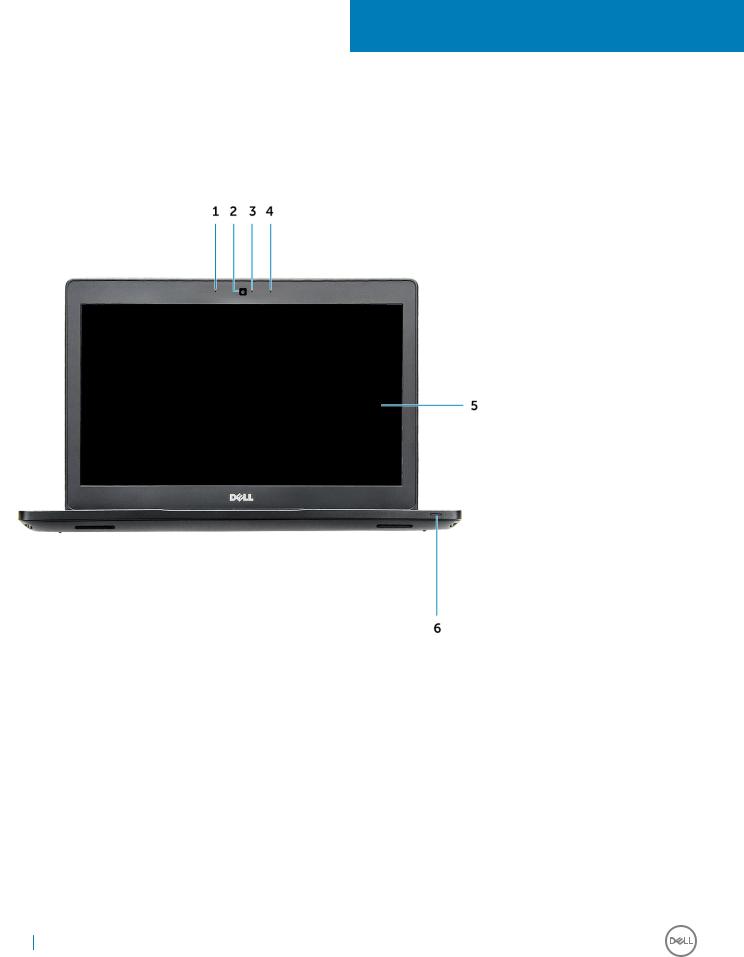
System front view
Figure 1. Front view
1Dual array microphone
2Camera
3Camera status light
4Dual array microphone
5Display
6Dattery and charge status light

 NOTE: Latitude 5480 computer also has an optional IR camera module.
10 Chassis view
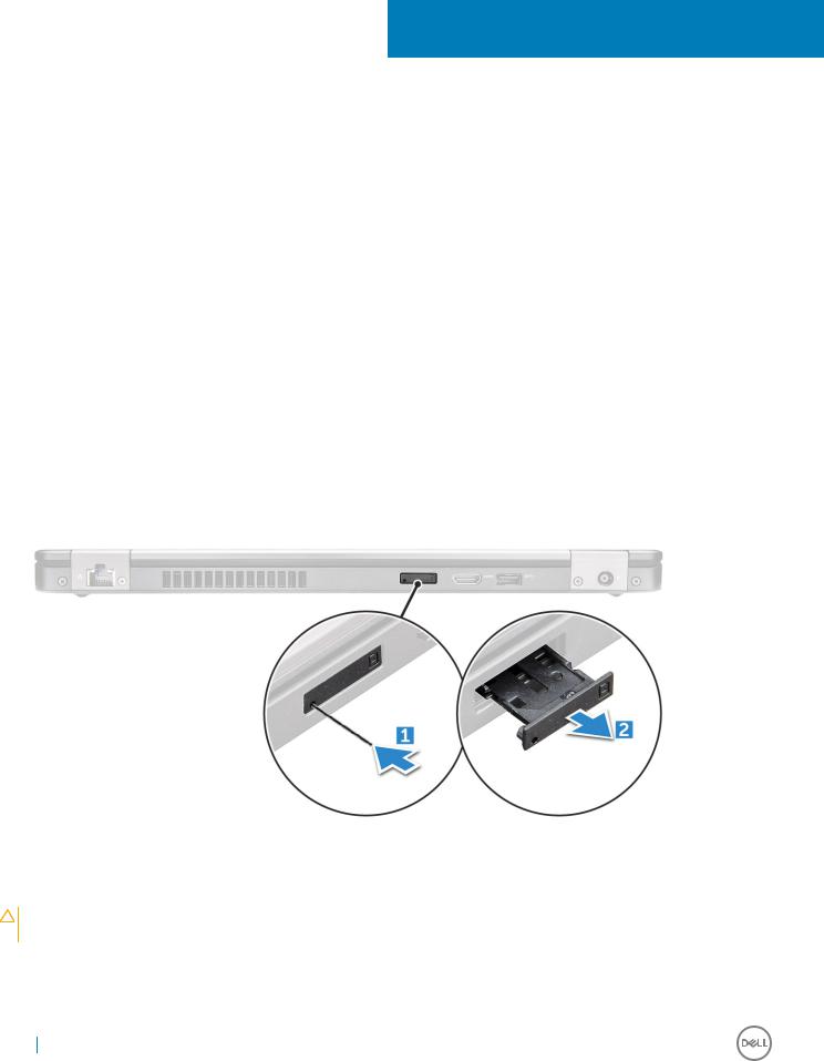
System back view
Figure 2. Back view
1Network port
2uSim card slot (optional)
3HDMI port
4USB 3.0 port
5Power connector port
System side view
Figure 3. Left view
1Type-C connector/DisplayPort or USB 3.0/optional Thunderbolt3
2USB 3.0 port
3SD card reader

 NOTE: Latitude 5480 computer also has an optional Smart card reader.
Chassis view |
11 |
|
|

System side view
Figure 4. Right view
1Headset/microphone port
2USB 3.0 port with PowerShare
3VGA port
4Noble wedge lock slot
12 Chassis view
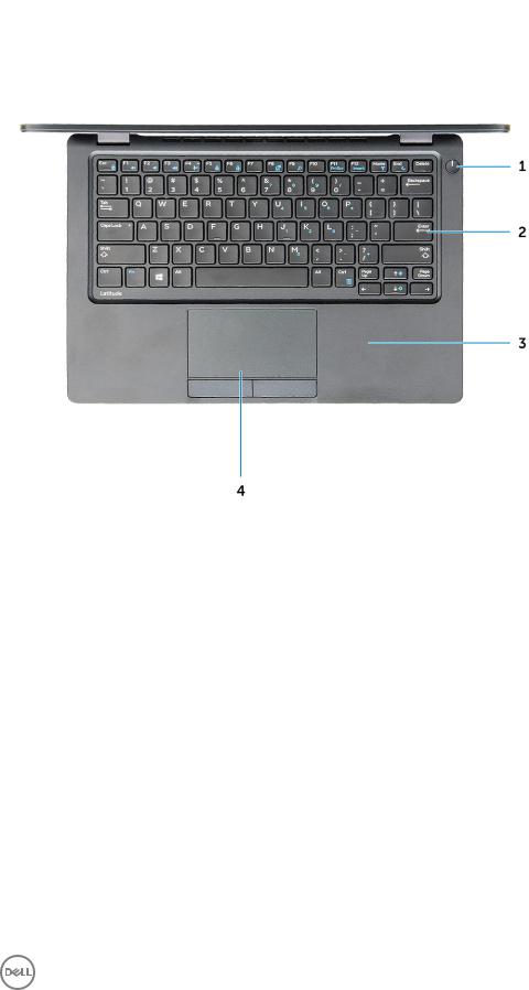
System top view
Figure 5. Top view
1Power button
2Keyboard
3Palm rest
4Touchpad

 NOTE: Latitude 5480 computer also has an optional fingerprint reader.
Chassis view |
13 |
|
|
3
Removing and installing components
This section provides detailed information on how to remove or install the components from your computer.
Recommended tools
The procedures in this document require the following tools:
•Phillips #0 screwdriver
•Phillips #1 screwdriver
•Small plastic scribe
Subscriber Identity Module(SIM) board
Installing the Subscriber Identification Module (SIM) card
1Follow the procedure in After working inside your computer.
2Insert a paperclip or a SIM card removal tool into the pinhole [1].
3Pull the SIM card tray to remove it [2].
4Place the SIM card on the SIM card tray.
5Push the SIM card tray into the slot until it clicks into place.
Removing the Subscriber Identification Module (SIM) card
CAUTION: Removing the SIM card when the computer is on may cause data loss or damage the card. Ensure your computer is turned off or the network connections are disabled.
1Insert a paperclip or a SIM card removal tool into the pinhole on the SIM card tray.
2Pull the SIM card tray to remove it.
3Remove the SIM card from the SIM card tray.
14 Removing and installing components
4 Push the SIM card tray into the slot until it clicks into place.
Base cover
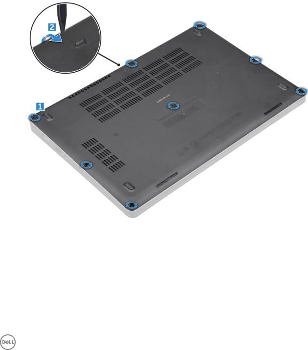
Removing base cover
1Follow the procedure in Before working inside your computer.
2To remove the base cover:
aLoosen the M2.5*6.3 captive screws that secure the base cover to the computer [1].
bPry the base cover from the edge and lift the base cover away from the computer [2].

 NOTE: You may need a plastic scribe to pry the base cover from the edges.
Installing base cover
1Place the base cover to align with the screw holders on the computer.
2Tighten the M2.5 captive screws to secure the base cover to the computer.
3Follow the procedure in After working inside your computer.
Removing and installing components |
15 |
|
|
Battery
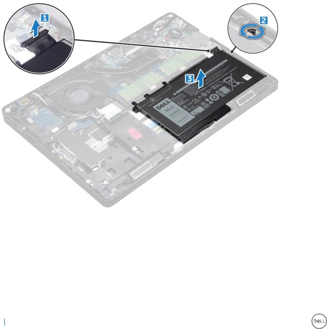
Removing battery
1Follow the procedure in Before working inside your computer.
2Remove the base cover.
3To remove the battery:
aDisconnect the battery cable from the connector on the system board [1].
bUnroute the battery cable from the routing channels.
cRemove the M2*6 captive screw that secures the battery to the computer [2].

 NOTE: 6-cell battery has 2 screws. d Lift the battery from the computer [3].
Installing battery
1Insert the battery into the slot on the computer.
2Route the battery cable through the routing channels.
3Tighten the M2*6 captive screw to secure the battery to the computer.
4Connect the battery cable to the connector on the system board.
5Install the base cover.
6Follow the procedure in After working inside your computer.
16 Removing and installing components
Solid State Drive (SSD)
Removing optional M.2 Solid State Drive (SSD)
1Follow the procedure in Before working inside your computer.
2Remove the:
abase cover
bbattery
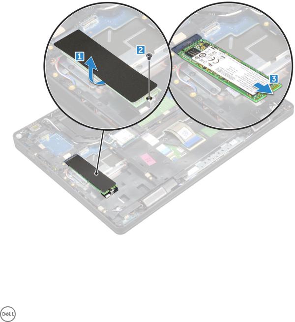
3 To remove the SSD card:
a Remove the SSD bracket from the SSD card.

 NOTE: The SSD bracket is shipped along with the SSD card kit.
bPeel the adhesive tape that secures the SSD card [1].
cRemove the M2*3 screw that secures the SSD to the computer [2].
dSlide and lift the SSD from the computer [3].
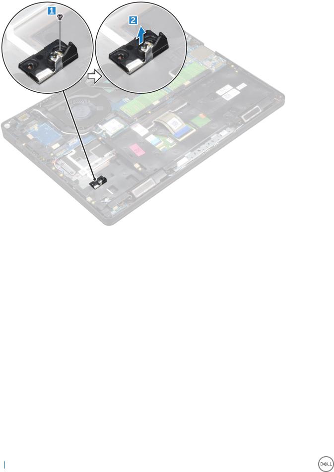
4 To remove the SSD clip:
aRemove the M2*3 screw that secures the SSD clip to the computer [1].
bLift the SSD clip away from the computer [2].
Removing and installing components |
17 |
|
|
Installing optional M.2 SSD
1Insert the SSD clip into the slot on the computer.
2Tighten the M2*3 screw to secure the SSD clip to the computer.
3Insert the SSD into the connector on the computer.
4Place the SSD bracket over the SSD and tighten the M2*3 screw to secure it to the computer.
5Install the:
abattery
bbase cover
6 Follow the procedure in After working inside your computer.
Hard drive
Removing hard drive assembly
1Follow the procedure in Before working inside your computer.
2Remove the:
abase cover
bbattery
3 To remove the hard drive assembly:
aDisconnect the hard drive cable from the connector on the system board.
bRemove the screws that secure the hard drive assembly to the computer.
18 Removing and installing components

c Lift the hard drive assembly away from the compute.
Installing hard drive assembly
1Insert the hard drive assembly into the slot on the computer.
2Tighten the screws to secure the hard drive assembly to the computer.
3Connect the hard drive cable to the connector on the hard drive and on the system board.
4Install the:
abattery
bbase cover
5 Follow the procedures in After working inside your system.
Coin cell battery
Removing the coin cell battery
1Follow the procedure in Before working inside your computer.
2Remove the:
abase cover
bbattery
3 To remove the coin cell battery:
aDisconnect the coin cell battery cable from the connector on the system board [1].
bLift the coin cell battery to release from the adhesive and lift it away from the system board [2].
Removing and installing components |
19 |
|
|
Installing coin cell battery
1Affix the coin cell battery on the system board.
2Connect the coin cell battery cable to the connector on the system board.
3Install the:
abattery
bbase cover
4 Follow the procedure in After working inside your computer.
WLAN card
Removing WLAN card
1Follow the procedure in Before working inside your computer.
2Remove the:
abase cover
bbattery
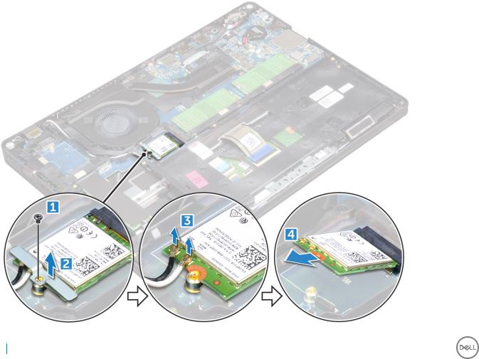
3 To remove the WLAN card:
aRemove the M2*3 screw that secures the WLAN card to the computer [1].
bRemove the metal bracket that secures the WLAN cables [2].
cDisconnect the WLAN cables from the connectors on the WLAN card [3].
dLift the WLAN card away from the connector [4].
20 Removing and installing components
Installing WLAN card
1Insert the WLAN card into the connector on the system board.
2Place the metal bracket to secure the WLAN cables.
3Tighten the M2*3 screw to secure the WLAN card to the computer.
4Connect the WLAN cables to the connectors on the WLAN card.
5Install the:
abattery
bbase cover
6 Follow the procedure in After working inside your computer.
Memory module
Removing memory module
1Follow the procedure in Before working inside your computer.
2Remove the:
abase cover
bbattery
3 To remove the memory module:
aPry the clips securing the memory module until the memory module pops-up [1].
bLift the memory module away from the connector [2].
Removing and installing components |
21 |
|
|
Installing memory module
1Insert the memory module on the memory connector until the clips secure the memory module.
2Install the:
abattery
bbase cover
3 Follow the procedure in After working inside your computer.
Keyboard
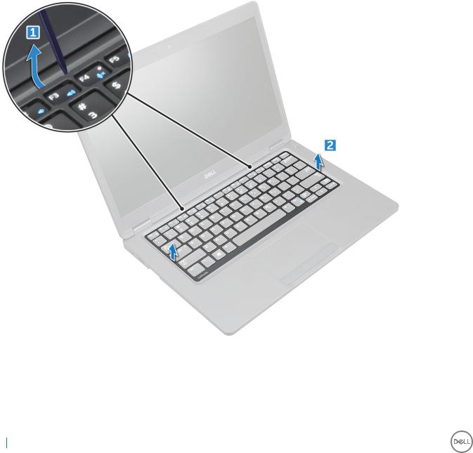
Removing keyboard trim
1Follow the procedure in Before working inside your computer.
2Pry the keyboard trim from the edges [1] and lift it away from the computer [2].

 NOTE: You may need a plastic scribe to pry the keyboard trim from the edges.
22 Removing and installing components
Installing keyboard trim
1Place the keyboard trim on the keyboard and press on the edges until it clicks in place.
2Follow the procedure in After working inside your computer.
Removing keyboard
1Follow the procedure in Before working inside your computer.
2Remove the:
abase cover
bbattery
ckeyboard trim
3 Lift the latch and disconnect the keyboard cable from the connector.
4Turn over the computer and open the display.
5To remove the keyboard:
aRemove the M2*2 screws that secure the keyboard to the computer [1].
bPry the keyboard from the edge and lift it away from the computer [2].
WARNING: Make sure you pull the keyboard cable routed under the computer to avoid any damage to the keyboard cable.
Removing and installing components |
23 |
|
|

Installing keyboard
1Hold the keyboard and route the keyboard cable through the placeholder.
2Place the keyboard to align with the screw holders on the computer.
3Tighten the M2*2 screws to secure the keyboard to the computer.
4Connect the keyboard cable to the connector.
5Install the:
akeyboard trim
bbattery
cbase cover
6 Follow the procedure in After working inside your computer.
Heat sink
Removing heatsink
1Follow the procedure in Before working inside your computer.
2Remove the:
abase cover
bbattery
24 Removing and installing components
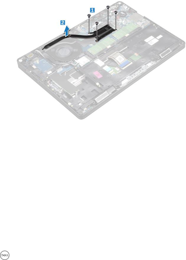
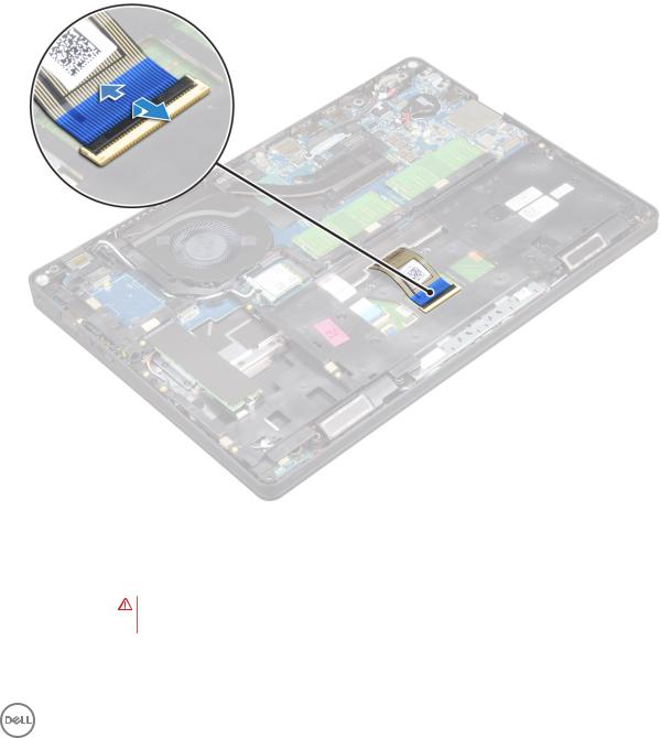
3 To remove the heat sink :
aDisconnect the system fan cable from the connector on the system board [1]
bRemove the M2*3 screws that secure the heat sink on the system board [2].
cLift the heat sink away from the system board.
Installing heat sink
1Place the heat sink on the system board.
2Tighten the M2*3 screws to secure the heat sink to the computer.
3Connect the system fan cable to the connector on the system board.
4Install the:
abattery
bbase cover
5 Follow the procedure in After working inside your computer.
System fan
Removing the system fan
1Follow the procedure in Before working inside your computer.
2Remove the:
abase cover
bbattery
cchassis frame
3 To remove the system fan:
Removing and installing components |
25 |
|
|
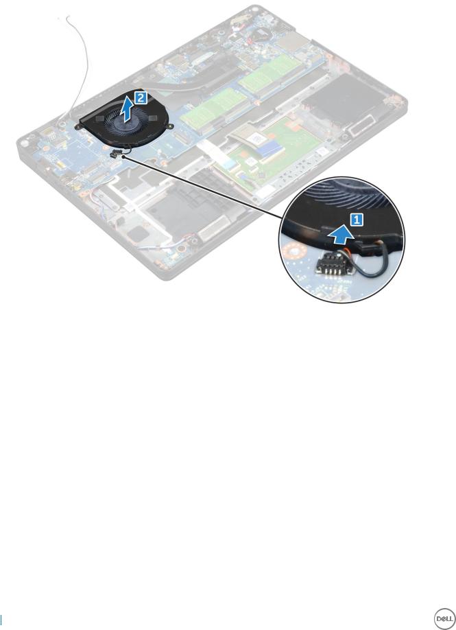
aDisconnect the system fan cable from the connector on the system board [1].
bLift the system fan away from the computer [2].
Installing the system fan
1Place the system fan into the slot on the computer.
2Connect the system fan cable to the connector on the system board.
3Install the:
achassis frame
bbattery
cbase cover
4 Follow the procedure in After working inside your computer.
Power connector port
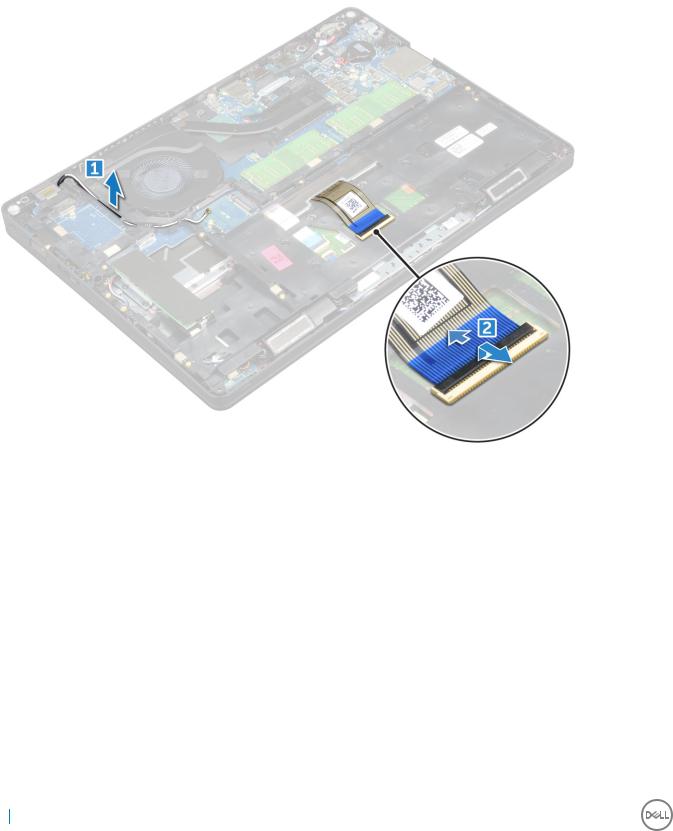
Removing power connector port
1Follow the procedure in Before working inside your computer.
2Remove the:
abase cover
bbattery
3 To remove the power connector port:
a Remove the M2*3 screw that secures the display cable to the computer [1].
26 Removing and installing components

bDisconnect the power connector port cable from the connector on the system board [2].
cRemove the M2*3 screw to release the metal bracket that secures the power connector port [3].
dLift the metal bracket [4].
eLift the power connector port away from the computer [5].
Installing power connector port
1Align the power connector port along the grooves on the slot and push it down.
2Place the metal bracket on the power connector port.
3Tighten the M2*3 screw to secure the power connector port to the computer
4Connect the power connector port cable to the connector on the system board.
5Tighten the M2*3 screw to secure the display cable to the computer.
6Install the:
abattery
bbase cover
7 Follow the procedure in After working inside your computer.
Chassis frame
Removing chassis frame
1Follow the procedure in Before working inside your computer.
2Remove the:
Removing and installing components |
27 |
|
|
abase cover
bbattery
cWLAN card
dSSD card
3 To release the chassis frame:
aRelease the WLAN cables from the routing channels [1].
bLift the latch and disconnect the keyboard cable from the connector [2].
4 To remove the chassis frame:
aRemove the M2*2, M2*3, and M2*5 screws that secure the chassis frame to the computer [1].
bLift the chassis frame away from the computer [2].
28 Removing and installing components
Loading...