


 Loading...
Dell Inspiron M5040/15-N5040/
15-N5050 Owner’s Manual
Regulatory model: P18F Regulatory type: P18F001; P18F002; P18F003

Notes, Cautions, and Warnings
NOTE: A NOTE indicates important information that helps you make better use of your computer.
CAUTION: A CAUTION indicates potential damage to hardware or loss of data if instructions are not followed.
WARNING: A WARNING indicates a potential for property damage, personal injury, or death.
____________________
Information in this document is subject to change without notice. © 2011 Dell Inc. All rights reserved.
Trademarks used in this text: Dell™, the DELL logo, and Inspiron™ are trademarks of Dell Inc.; Bluetooth® is a registered trademark owned by Bluetooth SIG, Inc.; Microsoft®, Windows®, and the Windows start button logo are either trademarks or registered trademarks of Microsoft Corporation in the United States and/or other countries.
Reproduction of these materials in any manner whatsoever without the written permission of Dell Inc. is strictly forbidden.
Regulatory model: P18F |
Regulatory type: P18F001; P18F002; P18F003 |
2011 - 05 |
Rev. A00 |
Contents
1 |
Before You Begin . . . . . . . . . . . . . . . . . . . . |
9 |
|
|
|
Recommended Tools. . . . . . . . . . . . . . . . . . . . |
9 |
|
|
|
Turning Off Your Computer. . . . . . . . . . . . . . . . . |
9 |
|
|
|
Before Working Inside Your Computer . . . . . . . . . |
10 |
|
|
2 |
Battery . . . . . . . . . . . . . . . . . . . . . . . . . . . |
13 |
|
|
|
Removing the Battery . . . . . . . . . . . . . . . . . . |
13 |
|
|
|
Replacing the Battery . . . . . . . . . . . . . . . . . . |
14 |
|
|
3 |
Keyboard . . . . . . . . . . . . . . . . . . . . . . . . . |
15 |
|
|
|
Removing the Keyboard . . . . . . . . . . . . . . . . . |
15 |
|
|
|
Replacing the Keyboard . . . . . . . . . . . . . . . . . |
17 |
|
|
4 |
Memory Module(s) . . . . . . . . . . . . . . . . . |
19 |
|
|
|
Removing the Memory Module(s) . . . . . . . . . . . . |
19 |
|
|
|
Replacing the Memory Module(s). . . . . . . . . . . . |
20 |
|
|
5 |
Optical Drive . . . . . . . . . . . . . . . . . . . . . . |
23 |
|
|
|
Removing the Optical Drive . . . . . . . . . . . . . . . |
23 |
|
|
|
Contents |
|
|
3 |
|
|

|
Replacing the Optical Drive . . . . . . . . . . . . . . . |
24 |
6 |
Wireless Mini-Card . . . . . . . . . . . . . . . . |
25 |
|
Removing the Mini-Card . . . . . . . . . . . . . . . . . |
25 |
|
Replacing the Mini-Card. . . . . . . . . . . . . . . . . |
27 |
7 |
Palm-Rest Assembly . . . . . . . . . . . . . . . |
29 |
|
Removing the Palm-Rest Assembly . . . . . . . . . . . |
29 |
|
Replacing the Palm-Rest Assembly . . . . . . . . . . . |
32 |
8 |
Power Button Board . . . . . . . . . . . . . . . |
35 |
|
Removing the Power Button Board . . . . . . . . . . . |
35 |
|
Replacing the Power Button Board . . . . . . . . . . . |
36 |
9 |
Hard Drive . . . . . . . . . . . . . . . . . . . . . . . |
37 |
|
Removing the Hard Drive . . . . . . . . . . . . . . . . |
37 |
|
Replacing the Hard Drive . . . . . . . . . . . . . . . . |
39 |
10 |
Coin-Cell Battery . . . . . . . . . . . . . . . . . . |
41 |
|
Removing the Coin-Cell Battery . . . . . . . . . . . . . |
41 |
|
Replacing the Coin-Cell Battery . . . . . . . . . . . . . |
42 |
4 Contents

11 |
USB Board . . . . . . . . . . . . . . . . . . . . . . . . |
43 |
|
Removing the USB Board . . . . . . . . . . . . . . . . |
43 |
|
Replacing the USB Board . . . . . . . . . . . . . . . . |
44 |
12 |
Thermal Cooling Assembly . . . . . . . . . . . |
45 |
|
Removing the Thermal Cooling Assembly . . . . . . . |
45 |
|
Replacing the Thermal Cooling Assembly . . . . . . . |
46 |
13Processor Module (For Inspiron
15-N5050/15-N5040 Only) . . . . . . . . . . . . 49
|
Removing the Processor Module . . . . . . . . . . . . |
49 |
|
Replacing the Processor Module . . . . . . . . . . . . |
50 |
14 |
Hinge Cover . . . . . . . . . . . . . . . . . . . . . . . |
53 |
|
Removing the Hinge Cover . . . . . . . . . . . . . . . |
53 |
|
Replacing the Hinge Cover . . . . . . . . . . . . . . . |
55 |
15 |
Display . . . . . . . . . . . . . . . . . . . . . . . . . . . |
57 |
|
Display Assembly . . . . . . . . . . . . . . . . . . . . |
57 |
|
Removing the Display Assembly . . . . . . . . . . |
57 |
|
Replacing the Display Assembly . . . . . . . . . . |
60 |
|
Display Bezel . . . . . . . . . . . . . . . . . . . . . . |
61 |
|
Removing the Display Bezel . . . . . . . . . . . . |
61 |
|
Replacing the Display Bezel . . . . . . . . . . . . |
62 |
Contents 5

|
Removing the Display Panel . . . . . . . . . . . . |
62 |
|
Replacing the Display Panel . . . . . . . . . . . . |
65 |
16 |
Camera Module . . . . . . . . . . . . . . . . . . . |
67 |
|
Removing the Camera Module. . . . . . . . . . . . . . |
67 |
|
Replacing the Camera Module . . . . . . . . . . . . . |
68 |
17 |
System Board . . . . . . . . . . . . . . . . . . . . . |
69 |
|
Removing the System Board . . . . . . . . . . . . . . . |
69 |
|
Replacing the System Board . . . . . . . . . . . . . . . |
71 |
|
Entering the Service Tag in the BIOS . . . . . . . . . . |
72 |
18 |
Flashing the BIOS . . . . . . . . . . . . . . . . . |
73 |
6 Contents

Contents 7

8 Contents

1
Before You Begin
This manual provides procedures for removing and installing components in your computer. Before you begin any procedure in this book, ensure that:
•You have performed the steps in "Turning Off Your Computer" on page 9 and "Before Working Inside Your Computer" on page 10.
•You have read the safety information that shipped with your computer.
•A component can be replaced or—if purchased separately—installed by performing the removal procedure in the reverse order.
Recommended Tools
The procedures in this document may require the following tools:
•Small flat-blade screwdriver
•Phillips screwdriver
•Plastic scribe
•BIOS executable update program available at support.dell.com
Turning Off Your Computer
CAUTION: To avoid losing data, save and close all open files and exit all open programs before you turn off your computer.
1Save and close all open files and exit all open programs.
2Click Start  and then click Shut Down.
The computer turns off after the operating system shutdown process is completed.
3Ensure that the computer is turned off. If your computer did not automatically turn off when you shut down the operating system, press and hold the power button until the computer turns off.
Before You Begin |
|
9 |
|

Before Working Inside Your Computer
Use the following safety guidelines to help protect your computer from potential damage and to ensure your own personal safety.
WARNING: Before working inside your computer, read the safety information that shipped with your computer. For additional safety best practices information, see the Regulatory Compliance Homepage at www.dell.com/regulatory_compliance.
CAUTION: To avoid electrostatic discharge, ground yourself by using a wrist grounding strap or by periodically touching an unpainted metal surface (such as a connector on your computer).
CAUTION: Handle components and cards with care. Do not touch the components or contacts on a card. Hold a card by its edges or by its metal mounting bracket. Hold a component such as a processor by its edges, not by its pins.
CAUTION: Only a certified service technician should perform repairs on your computer. Damage due to servicing that is not authorized by Dell is not covered by your warranty.
CAUTION: When you disconnect a cable, pull on its connector or on its pull-tab, not on the cable itself. Some cables have connectors with locking tabs; if you are disconnecting this type of cable, press in on the locking tabs before you disconnect the cable. As you pull connectors apart, keep them evenly aligned to avoid bending any connector pins. Also, before you connect a cable, ensure that both connectors are correctly oriented and aligned.
CAUTION: To avoid damaging the computer, perform the following steps before you begin working inside the computer.
1Ensure that the work surface is flat and clean to prevent the computer cover from being scratched.
2Turn off your computer (see "Turning Off Your Computer" on page 9) and all attached devices.
CAUTION: To disconnect a network cable, first unplug the cable from your computer and then unplug the cable from the network device.
3Disconnect all telephone or network cables from the computer.
4Press and eject any installed cards from the 3-in-1 media card reader.
5Disconnect your computer and all attached devices from their electrical outlets.
10 |
|
Before You Begin |
|
6Disconnect all attached devices from your computer.
CAUTION: To help prevent damage to the system board, remove the main battery (see "Removing the Battery" on page 13) before working inside the computer.
7Remove the battery (see "Removing the Battery" on page 13).
8Turn the computer top-side up, open the display, and press the power button to ground the system board.
Before You Begin |
|
11 |
|
12 |
|
Before You Begin |
|

2
Battery
WARNING: Before working inside your computer, read the safety information that shipped with your computer. For additional safety best practices information, see the Regulatory Compliance Homepage at www.dell.com/regulatory_compliance.
CAUTION: Only a certified service technician should perform repairs on your computer. Damage due to servicing that is not authorized by Dell is not covered by your warranty.
CAUTION: To avoid electrostatic discharge, ground yourself by using a wrist grounding strap or by periodically touching an unpainted metal surface (such as a connector on your computer).
CAUTION: To avoid damage to the computer, use only the battery designed for this particular Dell computer. Do not use batteries designed for other Dell computers.
Removing the Battery
1Follow the instructions in "Before You Begin" on page 9.
2Turn off the computer and turn it over.
3Slide the battery lock latch to the unlock position until it clicks into place.
4Slide and hold the battery release latch in the unlock position.
5Slide and lift the battery out of the battery bay.
Battery 13

3
2
1
1 |
battery release latch |
2 |
battery |
3 |
battery lock latch |
|
|
Replacing the Battery
1Follow the instructions in "Before You Begin" on page 9.
2Slide the battery into the battery bay until it clicks into place.
3Slide the battery lock latch to the lock position.
14 Battery

3
Keyboard
WARNING: Before working inside your computer, read the safety information that shipped with your computer. For additional safety best practices information, see the Regulatory Compliance Homepage at www.dell.com/regulatory_compliance.
CAUTION: Only a certified service technician should perform repairs on your computer. Damage due to servicing that is not authorized by Dell is not covered by your warranty.
CAUTION: To avoid electrostatic discharge, ground yourself by using a wrist grounding strap or by periodically touching an unpainted metal surface (such as a connector on your computer).
CAUTION: To help prevent damage to the system board, remove the main battery (see "Removing the Battery" on page 13) before working inside the computer.
Removing the Keyboard
1Follow the instructions in "Before You Begin" on page 9.
2Remove the battery (see "Removing the Battery" on page 13).
CAUTION: The keycaps on the keyboard are fragile, easily dislodged, and time-consuming to replace. Be careful when removing and handling the keyboard.
3Turn the computer over and open the display as far as possible.
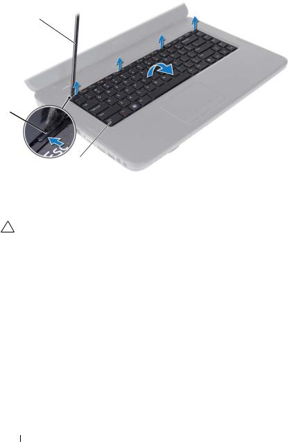
4Using a plastic scribe, release the four tabs that secure the keyboard to the palm rest and ease the keyboard up until it clears off the palm rest.
Keyboard 15
1
2
|
|
3 |
1 |
plastic scribe |
2 tabs (4) |
3 |
keyboard |
|
CAUTION: The keycaps on the keyboard are fragile, easily dislodged, and time-consuming to replace. Be careful when removing and handling the keyboard.
5Carefully turn the keyboard over and place it on the palm rest assembly.
6Lift the connector latch that secures the keyboard cable to the connector on the system board and remove the keyboard cable.
7Lift the keyboard off the computer.
16 Keyboard

1
2
1 |
keyboard cable |
2 keyboard |
Replacing the Keyboard
1Follow the instructions in "Before You Begin" on page 9.
2Slide the keyboard cable into the connector on the system board. Press down on the connector latch to secure the keyboard cable to the connector on the system board.
3Slide the tabs on the keyboard into the slots on the palm rest.
4Gently press around the edges of the keyboard to lock the four tabs securing the keyboard.
5Close the display and turn the computer over.
6Replace the battery (see "Replacing the Battery" on page 14).
Keyboard 17

18 Keyboard

4
Memory Module(s)
WARNING: Before working inside your computer, read the safety information that shipped with your computer. For additional safety best practices information, see the Regulatory Compliance Homepage at www.dell.com/regulatory_compliance.
CAUTION: Only a certified service technician should perform repairs on your computer. Damage due to servicing that is not authorized by Dell is not covered by your warranty.
CAUTION: To avoid electrostatic discharge, ground yourself by using a wrist grounding strap or by periodically touching an unpainted metal surface (such as a connector on your computer).
CAUTION: To help prevent damage to the system board, remove the main battery (see "Removing the Battery" on page 13) before working inside the computer.
You can increase your computer memory by installing memory modules on the system board. See the Specifications at support.dell.com/manuals for information on the type of memory supported by your computer.
NOTE: Memory modules purchased from Dell are covered under your computer warranty.
Your computer has two user-accessible SODIMM sockets, labeled DIMM A and DIMM B, that can be accessed from the bottom of the computer.
Removing the Memory Module(s)
1Follow the instructions in "Before You Begin" on page 9.
2Remove the battery (see "Removing the Battery" on page 13).
3Remove the keyboard (see "Removing the Keyboard" on page 15).
CAUTION: To prevent damage to the memory module connector, do not use tools to spread the memory module securing clips.
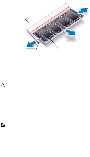
4Use your fingertips to carefully spread apart the securing clips on each end of the memory-module connector until the module pops up.
5Remove the memory module from the memory-module connector.
Memory 19
1
 3
3
2
1 memory-module connector 2 securing clips (2)
3 memory module
Replacing the Memory Module(s)
CAUTION: If you need to install memory modules in two connectors, install a memory module in the connector labeled “DIMM A” before you install a memory module in the connector labeled “DIMM B.”
1Follow the instructions in "Before You Begin" on page 9.
2Align the notch in the memory module with the tab in the memory-module connector.
3Slide the memory module firmly into the slot at a 45-degree angle, and press the memory module down until it clicks into place. If you do not hear the click, remove the memory module and reinstall it.
NOTE: If the memory module is not installed properly, the computer may not boot.
20 Memory
2
1
1 tab 2 notch
4Replace the keyboard (see "Replacing the Keyboard" on page 17).
5Replace the battery (see "Replacing the Battery" on page 14), or connect the AC adapter to your computer and an electrical outlet.
CAUTION: Before turning on the computer, replace all screws and ensure that no stray screws remain inside the computer. Failure to do so may result in damage to the computer.
6Turn on the computer.
As the computer boots, it detects the memory module(s) and automatically updates the system configuration information.
To confirm the amount of memory installed in the computer:
Click Start  → Control Panel→ System and Security→ System.
Memory 21

22 Memory

5
Optical Drive
WARNING: Before working inside your computer, read the safety information that shipped with your computer. For additional safety best practices information, see the Regulatory Compliance Homepage at www.dell.com/regulatory_compliance.
CAUTION: Only a certified service technician should perform repairs on your computer. Damage due to servicing that is not authorized by Dell is not covered by your warranty.
CAUTION: To avoid electrostatic discharge, ground yourself by using a wrist grounding strap or by periodically touching an unpainted metal surface (such as a connector on your computer).
CAUTION: To help prevent damage to the system board, remove the main battery (see "Removing the Battery" on page 13) before working inside the computer.
Removing the Optical Drive
1Follow the instructions in "Before You Begin" on page 9.
2Remove the battery (see "Removing the Battery" on page 13).
3Remove the keyboard (see "Removing the Keyboard" on page 15).
4Remove the screw that secures the optical drive to the computer base.
5Using a plastic scribe, push the notch on the optical drive to release it from the optical-drive compartment.
6Slide the optical drive out of the optical-drive compartment.
Optical Drive |
|
23 |
|
Loading...