


DellTM XFR D630
Fully Rugged Notebook
Service Manual

DellTM XFR D630 Fully Rugged Notebook Service Manual
Notes, Notices, and Cautions
NOTE: A NOTE indicates important information that helps you make better use of your computer.
NOTICE: A NOTICE indicates either potential damage to hardware or loss of data and tells you how to avoid the problem.
CAUTION: A CAUTION indicates a potential for property damage, personal injury, or death.
Information in this document is subject to change without notice. Some of the information contained in this document may not apply to all Dell systems.
© 2008 Dell Inc. All rights reserved.
Reproduction in any manner whatsoever without the written permission of Dell Inc. is strictly forbidden
This document is provided for informational purposes only, and may contain typographical errors and technical inaccuracies. The content is provided as is, without express or implied warranties of any kind.
Trademarks used in this text: Dell, the DELL logo, and Latitude are registered trademarks of Dell Inc.; DirectVue is a trademark of Augmentix Corporation; Windows and Windows Vista are registered trademarks of Microsoft Corporation; Bluetooth is a registered trademark owned by Bluetooth SIG, Inc. and is used by Dell under license.
Other trademarks and trade names may be used in this document to refer to either the entities claiming the marks and names or their products. Dell Inc. disclaims any proprietary interest in trademarks and trade names other than its own.
Page 2 of 106 |
Revision A01 |
DellTM XFR D630 Fully Rugged Notebook Service Manual
Table of Contents
1 |
BEFORE YOU BEGIN ..................................................................................................... |
6 |
||
|
1.1 |
|
RECOMMENDED TOOLS .................................................................................................... |
6 |
|
1.2 |
|
TURNING OFF YOUR COMPUTER......................................................................................... |
6 |
|
1.3 |
|
BEFORE WORKING INSIDE YOUR COMPUTER ........................................................................ |
6 |
|
1.4 |
|
SCREW CHART............................................................................................................... |
8 |
2 |
XBAY DEVICES ............................................................................................................ |
13 |
||
3 |
HARD DRIVE................................................................................................................ |
14 |
||
4 |
STYLUS, TETHER AND CLIP (DIRECTVUE TOUCH SCREEN DISPLAY OPTION) ... |
17 |
||
|
4.1 |
|
REPLACING THE STYLUS CLIP........................................................................................... |
17 |
|
4.2 |
|
REPLACING THE STYLUS.................................................................................................. |
19 |
5 |
HANDLE........................................................................................................................ |
19 |
||
|
5.1 |
|
REMOVING THE HANDLE.................................................................................................. |
20 |
|
5.2 |
|
INSTALLING THE HANDLE ................................................................................................ |
20 |
6 |
PORT COVERS ............................................................................................................. |
21 |
||
|
6.1 |
|
COMMS DOOR .............................................................................................................. |
21 |
|
6.2 |
|
DOCKING DOOR............................................................................................................ |
22 |
|
6.3 |
|
VGA DOOR.................................................................................................................. |
25 |
|
6.4 |
|
POWER DOOR............................................................................................................... |
28 |
|
6.5 |
|
XBAY DOOR ................................................................................................................. |
29 |
|
6.6 |
|
AUDIO PORTS/WIFI DOOR.............................................................................................. |
31 |
|
6.7 |
|
USB SIDE DOOR .......................................................................................................... |
32 |
|
6.8 |
|
USB REAR DOOR.......................................................................................................... |
34 |
|
6.9 |
|
PC CARD SLOT DOOR .................................................................................................... |
35 |
7 |
HINGE COVER ............................................................................................................. |
37 |
||
|
7.1 |
|
REMOVING THE HINGE COVER.......................................................................................... |
37 |
|
7.2 |
|
INSTALLING THE HINGE COVER ........................................................................................ |
39 |
8 |
KEYBOARDS ................................................................................................................ |
39 |
||
|
8.1 |
|
STANDARD KEYBOARD.................................................................................................... |
39 |
|
8.2 |
|
RUGGED KEYBOARD ....................................................................................................... |
41 |
9 |
MEMORY ...................................................................................................................... |
51 |
||
|
9.1 |
|
DIMM A ..................................................................................................................... |
51 |
|
9.2 |
|
DIMM B ..................................................................................................................... |
53 |
10 |
DISPLAY ASSEMBLY ................................................................................................ |
55 |
||
|
10.1 |
REMOVING THE DISPLAY ASSEMBLY................................................................................ |
56 |
|
|
10.2 |
INSTALLING THE DISPLAY ASSEMBLY .............................................................................. |
60 |
|
|
10.3 |
REMOVING THE DISPLAY BEZEL ..................................................................................... |
62 |
|
|
10.4 |
INSTALLING THE DISPLAY BEZEL.................................................................................... |
63 |
|
|
10.5 |
REMOVING THE DISPLAY PANEL ..................................................................................... |
63 |
|
|
10.6 |
INSTALLING THE DISPLAY PANEL.................................................................................... |
65 |
|
|
10.7 |
REMOVING THE DISPLAY TOP COVER .............................................................................. |
66 |
|
|
10.8 |
INSTALLING THE DISPLAY TOP COVER............................................................................. |
66 |
|
|
10.9 |
REMOVING THE DISPLAY LATCH ..................................................................................... |
67 |
|
Page 3 of 106 |
Revision A01 |
DellTM XFR D630 Fully Rugged Notebook Service Manual
10.10 |
INSTALLING THE DISPLAY LATCH.................................................................................... |
68 |
|
11 |
INTERNAL CARD WITH BLUETOOTH® WIRELESS TECHNOLOGY....................... |
68 |
|
11.1 |
REMOVING THE BLUETOOTH® WIRELESS CARD ................................................................ |
68 |
|
11.2 |
INSTALLING THE BLUETOOTH® WIRELESS CARD............................................................... |
69 |
|
12 |
WWAN, FCM & SIM CARDS ..................................................................................... |
70 |
|
12.1 |
MOBILE BROADBAND NETWORK (WWAN) CARD .............................................................. |
70 |
|
12.2 |
FLASH CACHE MODULE ................................................................................................ |
73 |
|
12.3 |
SUBSCRIBER IDENTITY MODULE (SIM) CARD................................................................... |
75 |
|
13 |
COIN-CELL BATTERY ............................................................................................... |
76 |
|
13.1 |
REMOVING THE COIN-CELL BATTERY .............................................................................. |
76 |
|
13.2 |
INSTALLING THE COIN-CELL BATTERY............................................................................. |
77 |
|
14 |
PALM REST................................................................................................................ |
78 |
|
14.1 |
REMOVING THE PALM REST........................................................................................... |
78 |
|
14.2 |
INSTALLING THE PALM REST ......................................................................................... |
80 |
|
15 |
WIRELESS LOCAL AREA NETWORK (WLAN) CARDS............................................ |
81 |
|
15.1 |
REMOVING THE WLAN CARD ........................................................................................ |
81 |
|
15.2 |
INSTALLING THE WLAN CARD....................................................................................... |
83 |
|
16 |
MODEM...................................................................................................................... |
84 |
|
16.1 |
REMOVING THE MODEM ............................................................................................... |
84 |
|
16.2 |
INSTALLING THE MODEM .............................................................................................. |
85 |
|
17 |
PROCESSOR THERMAL-COOLING ASSEMBLY ....................................................... |
85 |
|
17.1 |
REMOVING THE PROCESSOR THERMAL-COOLING ASSEMBLY ................................................ |
86 |
|
17.2 |
INSTALLING THE PROCESSOR THERMAL-COOLING ASSEMBLY ............................................... |
87 |
|
18 |
PROCESSOR.............................................................................................................. |
88 |
|
18.1 |
REMOVING THE PROCESSOR.......................................................................................... |
88 |
|
18.2 |
INSTALLING THE PROCESSOR ........................................................................................ |
89 |
|
19 |
PC CARD READER..................................................................................................... |
90 |
|
19.1 |
REMOVING THE PC CARD CAGE ..................................................................................... |
91 |
|
19.2 |
INSTALLING THE PC CARD CAGE.................................................................................... |
92 |
|
20 |
SPEAKER ................................................................................................................... |
92 |
|
20.1 |
REMOVING THE SPEAKER.............................................................................................. |
92 |
|
20.2 |
INSTALLING THE SPEAKER ............................................................................................ |
93 |
|
21 |
FAN............................................................................................................................ |
93 |
|
21.1 |
REMOVING THE FAN .................................................................................................... |
93 |
|
21.2 |
INSTALLING THE FAN................................................................................................... |
94 |
|
22 |
SYSTEM BOARD........................................................................................................ |
95 |
|
22.1 |
REMOVING THE SYSTEM BOARD..................................................................................... |
95 |
|
22.2 |
INSTALLING THE SYSTEM BOARD ................................................................................... |
98 |
|
23 |
FLASHING THE BIOS ............................................................................................. |
101 |
|
23.1 |
FLASHING THE BIOS FROM A CD ................................................................................ |
101 |
|
23.2 |
FLASHING THE BIOS FROM THE HARD DRIVE................................................................. |
101 |
|
Page 4 of 106 |
Revision A01 |
||
DellTM XFR D630 Fully Rugged Notebook Service Manual
24 |
RF PASSTHRU BOARD ........................................................................................... |
102 |
|
24.1 |
REMOVING THE RF PASSTHRU BOARD........................................................................... |
102 |
|
24.2 |
INSTALLING THE RF PASSTHRU BOARD ......................................................................... |
103 |
|
25 |
BOTTOM CHASSIS.................................................................................................. |
104 |
|
25.1 |
REMOVING THE BOTTOM CHASSIS................................................................................ |
104 |
|
25.2 |
INSTALLING THE BOTTOM CHASSIS .............................................................................. |
105 |
|
25.3 |
REMOVING THE MODEM CABLE .................................................................................... |
105 |
|
25.4 |
INSTALLING THE MODEM CABLE................................................................................... |
105 |
|
Page 5 of 106 |
Revision A01 |

DellTM XFR D630 Fully Rugged Notebook Service Manual
1 Before You Begin
This chapter provides procedures for removing and installing the components in your computer. Unless otherwise noted, each procedure assumes that the following:
•You have performed the steps in Turning Off Your Computer and Before Working Inside Your Computer.
•You have read the safety information in the XFR D630 Product Information Guide and in the XFR D630 User’s Guide.
•A component can be replaced by performing the removal procedure in reverse order.
1.1Recommended Tools
The procedures in this document may require the following tools:
•Small flat-blade screwdriver
•Phillips screwdriver
•Small plastic scribe
•5-mm hex nut driver
•Flash BIOS-update program CD
•Processor extraction tool
•Torque driver capable of up to 1.5 inches/pound
•Display grommet tool (used when replacing the Display Assembly or the Display Top Cover Assembly)
1.2Turning Off Your Computer
NOTICE: To avoid losing data, save and close any open files and exit any open programs before you turn off your computer.
1.Shut down the operating system:
a.Save and close any open files, exit any open programs
b.Click Start→ Shut Down→ Shut down.
The computer turns off after the operating system shutdown process finishes.
2.Ensure that the computer and any attached devices are turned off. If your computer and attached devices do not automatically turn off when you shut down your operating system, press and hold the power button for 4 seconds.
1.3Before Working Inside Your Computer
Use the following safety guidelines to help protect your computer from potential damage and to help ensure your own personal safety.
CAUTION: Before you begin any of the procedures in this section, follow the safety instructions in the XFR D630 Product Information Guide and in the XFR D630 User’s Guide.
CAUTION: Handle components and cards with care. Do not touch the components or contacts on a card. Hold a card by its edges or by its metal mounting bracket. Hold a component such as a processor by its edges, not by its pins.
NOTICE: Only a certified service technician should perform repairs on your computer. Damage due to servicing that is not authorized by Dell is not covered by your warranty.
NOTICE: When you disconnect a cable, pull on its connector or on its pull-tab, not on the cable
Page 6 of 106 |
Revision A01 |
DellTM XFR D630 Fully Rugged Notebook Service Manual
itself. Some cables have a connector with locking tabs; if you are disconnecting this type of cable, press in on the locking tabs before you disconnect the cable. As you pull connectors apart, keep them evenly aligned to avoid bending any connector pins. Also, before you connect a cable, ensure that both connectors are correctly oriented and aligned.
NOTICE: To avoid damaging the computer, perform the following steps before you begin working inside the computer.
1.Ensure that the work surface is flat and clean to prevent the computer cover from being scratched.
2.Turn off your computer (see Turning Off Your Computer).
NOTICE: To disconnect a network cable, first unplug the cable from your computer and then unplug it from the network device.
3.Disconnect any telephone, network. And USB cables from the computer.
4.Disconnect your computer and all attached devices from their electrical outlets.
5.Turn over the computer.
NOTICE: To avoid damaging the system board, you must remove the main battery before you service the computer.
6. Remove the battery.
a.If the 2 screws that secure the quarter-turn latches are installed, remove the 2 screws on the latches on the battery compartment using a #1 Philips screw driver. See the figure above for the location of the battery compartment. If the 2 security screws are not installed, proceed to step b.
b.Lift each latch and turn each a quarter-turn, toward the ‘unlock’ icon, to release the latching mechanism. Remove the compartment cover from the computer.
c.To remove the battery from the compartment, utilize the tab on the battery to assist in lifting the battery from the compartment.
7.Press the power button to ground the system board.
8.Remove any PC Card or ExpressCard, if installed, from the PC Card slot.
a.The PC Card slot is located on the left, front side of the notebook.
b.To access the PC Card or ExpressCard, lower the protective door.
Page 7 of 106 |
Revision A01 |
DellTM XFR D630 Fully Rugged Notebook Service Manual
PC Card Slot
c.Remove the PC Card or Express Card.
d.Then close the protective door.
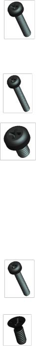
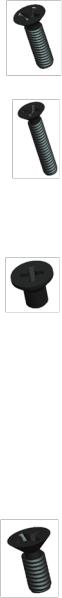
1.4Screw Chart
SCREW IMAGE |
|
PART |
|
DESCRIPTION |
Qty/Assy |
|
Total |
|
|
|
|
|
|||||
|
NUMBER |
|
|
Qty |
|
|||
|
|
|
|
|
|
|
||
|
|
|
|
|
|
|
|
|
|
18114 |
|
SHOULDER SCREW M2.5 |
|
|
|
|
|
|
|
|
|
|
|
6 |
|
|
|
18815 |
|
XFR LCD ASSY TOUCH SCREEN |
6 |
|
|
|
|
|
|
|
|
|
|
|
|
|
|
18279 |
|
CHEESE HEAD SCREW M1.2 X 3 |
|
|
|
|
|
|
|
|
|
|
|
|
|
|
|
18806 |
|
AV DOOR ASSY |
1 |
3 |
|
||
|
|
|
|
|
|
|
||
|
18808 |
|
VGA DOOR ASSY |
1 |
|
|
|
|
|
|
|
|
|
|
|
|
|
|
18812 |
|
DVD DOOR ASSY |
1 |
|
|
|
|
|
|
|
|
|
|
|
|
|
|
18353 |
|
SHOULDER SCREW-HEAT SPREADER |
|
|
|
|
|
|
|
|
|
|
|
3 |
|
|
|
18035 |
|
HEAT SINK ASSY |
3 |
|
|
|
|
|
|
|
|
|
|
|
||
|
18415 |
|
PAN HEAD SCREW M2.5 X 8 -BLACK |
|
19 |
|
||
|
|
|
|
|
|
|
|
|
Page 8 of 106 |
Revision A01 |
DellTM XFR D630 Fully Rugged Notebook Service Manual
|
18815 |
XFR LCD ASSY TOUCH SCREEN |
4 |
|
|
|
|
|
|
|
18802 |
PALMREST ASSY |
11 |
|
|
|
|
|
|
|
18043 |
ASSY HANDLE WITH HOLDER |
2 |
|
|
|
|
|
|
|
18619 |
LCD LATCH ASSY |
2 |
|
|
|
|
|
|
|
18416 |
SCR,M3X14,PHH,MSCR,ZPS,XFR |
|
|
|
|
|
|
8 |
|
18044 |
ASSY HANDLE |
6 |
|
|
|
|||
|
|
|
|
|
|
18824 |
SHOULDER STRAP ASSY |
2 |
|
|
|
|
|
|
|
18417 |
PAN HEAD SCREW M2 X 12 -BLACK |
|
|
|
|
|
|
7 |
|
18815 |
XFR LCD ASSY TOUCH SCREEN |
7 |
|
|
|
|
|
|
|
18419 |
PAN HEAD SCREW M2.5 X 4 -BLACK |
|
|
|
|
|
|
|
|
18810 |
HDD DOOR ASSY |
4 |
|
|
|
|
|
|
|
18813 |
RJ DOOR ASSY |
3 |
12 |
|
|
|
|
|
|
18814 |
USB PLASTIC DOOR ASSY |
1 |
|
|
|
|
|
|
|
18034 |
FAN ASSY |
3 |
|
|
|
|
|
|
|
9999-8024 |
PCMCIA HOLDER |
1 |
|
|
|
|
|
|
|
18420 |
PAN HEAD SCREW M2.5 X 14 -BLACK |
|
|
|
|
|
|
1 |
|
18802 |
PALMREST ASSY |
1 |
|
|
|
|
|
|
|
18423 |
CSK SCREW M2 X 5 -BLACK |
|
22 |
|
|
|
|
|
Page 9 of 106 |
Revision A01 |
DellTM XFR D630 Fully Rugged Notebook Service Manual
|
18806 |
AV DOOR ASSY |
4 |
|
|
|
|
|
|
|
18810 |
HDD DOOR ASSY |
2 |
|
|
|
|
|
|
|
18804 |
FAN COVER |
4 |
|
|
|
|
|
|
|
18807 |
BATTERY DOOR ASSY |
2 |
|
|
|
|
|
|
|
18811 |
DOCKING DOOR ASSY |
6 |
|
|
|
|
|
|
|
18623 |
KEYBOARD ASSY |
4 |
|
|
|
|
|
|
|
18424 |
CSK SCREW M3 X 10 -BLACK |
|
|
|
|
|
|
4 |
|
18043 |
ASSY HANDLE WITH HOLDER |
4 |
|
|
|
|
|
|
|
18425 |
CSK SCREW M2 X 10 -BLACK |
|
|
|
|
|
|
4 |
|
18043 |
ASSY HANDLE WITH HOLDER |
2 |
|
|
|
|||
|
|
|
|
|
|
18044 |
ASSY HANDLE |
2 |
|
|
|
|
|
|
|
18426 |
CSK SCREW M2 X 3 -BLACK |
|
|
|
|
|
|
|
|
18806 |
AV DOOR ASSY |
2 |
|
|
|
|
|
|
|
18808 |
VGA DOOR ASSY |
2 |
10 |
|
|
|
|
|
|
18812 |
DVD DOOR ASSY |
2 |
|
|
|
|
|
|
|
18802 |
PALMREST ASSY |
2 |
|
|
|
|
|
|
|
18618 |
AV DOOR COVER ASSY |
2 |
|
|
|
|
|
|
|
18427 |
CSK SCREW M2.5 X 6 -BLACK |
|
3 |
|
|
|
|
|
Page 10 of 106 |
Revision A01 |
DellTM XFR D630 Fully Rugged Notebook Service Manual
|
18808 |
VGA DOOR ASSY |
1 |
|
|
|
|
|
|
|
18812 |
DVD DOOR ASSY |
2 |
|
|
|
|
|
|
|
18428 |
CSK SCREW M2 X 8 -BLACK |
|
|
|
|
|
|
|
|
18815 |
XFR LCD ASSY TOUCH SCREEN |
2 |
|
|
|
|
|
|
|
18808 |
VGA DOOR ASSY |
2 |
10 |
|
|
|
|
|
|
18802 |
PALMREST ASSY |
2 |
|
|
|
|
|
|
|
18813 |
RJ DOOR ASSY |
2 |
|
|
|
|
|
|
|
18814 |
USB PLASTIC DOOR ASSY |
2 |
|
|
|
|
|
|
|
18429 |
CSK SCREW M2 X 6 -BLACK |
|
|
|
|
|
|
|
|
18810 |
HDD DOOR ASSY |
2 |
|
|
|
|
|
|
|
18807 |
BATTERY DOOR ASSY |
2 |
|
|
|
|
|
|
|
18630 |
USB SIDE DOOR ASSY |
2 |
30 |
|
|
|
|
|
|
18809 |
DIMMS DOOR ASSY |
4 |
|
|
|
|
|
|
|
18631 |
POWER DOOR ASSY |
2 |
|
|
|
|
|
|
|
18632 |
PCMCIA DOOR ASSY |
3 |
|
|
|
|
|
|
|
18628 |
RUBBER KEYBOARD ASSY |
15 |
|
|
|
|
|
|
|
18444 |
SCR,M2.5X5,PHH,TF,BCS |
|
|
|
|
|
|
10 |
|
18815 |
XFR LCD ASSY TOUCH SCREEN |
6 |
|
|
|
|||
|
|
|
|
|
|
18803 |
MOTHERBOARD TO CHASSIS |
4 |
|
|
|
|
|
|
Page 11 of 106 |
Revision A01 |

DellTM XFR D630 Fully Rugged Notebook Service Manual
|
18451 |
PAN HEAD SCREW M2 X 8-BLACK |
|
|
|
|
|
|
1 |
|
18802 |
PALMREST ASSY |
1 |
|
|
|
|
|
|
|
18477 |
PANHEAD SCREW M2X4 |
|
|
|
|
|
|
|
|
18802 |
PALMREST ASSY |
1 |
|
|
|
|
|
9 |
|
18043 |
ASSY HANDLE WITH HOLDER |
4 |
|
|
|
|||
|
|
|
|
|
|
18803 |
RF PASS THROUGH |
2 |
|
|
|
|
|
|
|
18819 |
LCD TOP COVER ASSY |
2 |
|
|
|
|
|
|
|
18517 |
SCR,M3X6,PHH,MSCR,ZPS,XFR |
|
|
|
|
|
|
2 |
|
18044 |
ASSY HANDLE |
2 |
|
|
|
|
|
|
|
18535 |
CSK CAPTIVE SCREW M2 X 6 |
|
|
|
|
|
|
19 |
|
18623 |
KEYBOARD ASSY |
15 |
|
|
|
|||
|
|
|
|
|
|
18816 |
HINGE COVER ASSY |
4 |
|
|
|
|
|
|
|
18539 |
PAN HEAD SCREW M3 X 14 -BLACK |
|
|
|
|
|
|
1 |
|
18629 |
STYLUS KIT ASSY |
1 |
|
|
|
|
|
|
|
18550 |
PAN HEAD SCREW M3 X 22 -BLACK |
|
|
|
|
|
|
2 |
|
18824 |
SHOULDER STRAP ASSY |
2 |
|
|
|
|
|
|
|
18590 |
SCREW,KYBD BLK, PAN HEAD M2X3 |
|
19 |
|
|
|
|
|
Page 12 of 106 |
Revision A01 |

DellTM XFR D630 Fully Rugged Notebook Service Manual
|
18815 |
XFR LCD ASSY TOUCH SCREEN |
8 |
|
|
|
|
|
|
|
18802 |
PALMREST ASSY |
2 |
|
|
|
|
|
|
|
18803 |
CARD CAGE ON BASE CHASSIS |
4 |
|
|
|
|
|
|
|
18623 |
KEYBOARD ASSY |
3 |
|
|
|
|
|
|
|
18823 |
MOTHERBOARD ASSY |
2 |
|
|
|
|
|
|
|
18591 |
PAN HEAD SCREW M2.5X8 |
|
|
|
|
|
|
2 |
|
18802 |
PALMREST ASSY |
2 |
|
|
|
|
|
|
|
18634 |
JACK SCREW FOR VGA PORT COVER |
|
|
|
|
|
|
4 |
|
18617 |
VGA SUPPORT ASSY |
4 |
|
|
|
|
|
|
|
18642 |
CSK SCREW M2 X 6.6 |
|
|
|
|
|
|
4 |
|
18802 |
PALMREST ASSY |
4 |
|
|
|
|
|
|
|
18671 |
PAN HEAD CAPTIVE SCREW-DVD M2 X |
|
|
|
12 |
|
|
|
|
|
|
1 |
|
|
|
|
|
|
|
18804 |
CHASSIS GASKET ASSY |
1 |
|
|
|
|
|
|
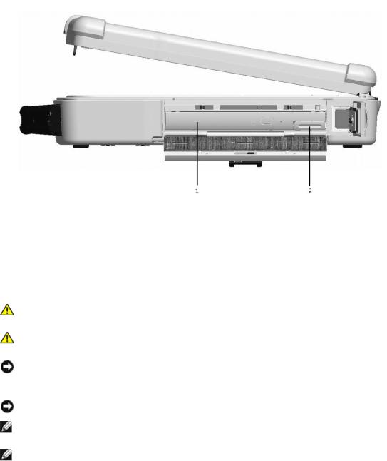
2 XBay Devices
NOTICE: To prevent damage to devices, store them in a safe, dry place when they are not installed in the computer. Avoid pressing down on them or placing heavy objects on top of them.
NOTE: If the device locking screw is not present, you can remove and install devices while the computer is running and connected to a docking device (docked).
1.If present, remove the device locking screw from the bottom of the computer.
2.If the computer is running, double-click the Safely Remove Hardware icon on the taskbar, click the device you want to eject, and click Stop.
3.Press the device latch release.
Page 13 of 106 |
Revision A01 |
DellTM XFR D630 Fully Rugged Notebook Service Manual
1 |
Optical drive |
2 |
Device Latch release |
|
|
|
|
4. Pull the device out of the XBay.
To install a device, push the new device into the XBay until it clicks into place.
3 Hard Drive
CAUTION: If you remove the hard drive from the computer when the drive is hot, do not touch the metal housing of the hard drive.
CAUTION: Before working inside your computer, follow the safety instructions in the
XFR D630 Product Information Guide and in the XFR D630 User’s Guide.
NOTICE: To prevent data loss, turn off your computer before removing the hard drive. Do not remove the hard drive while the computer is on, in standby mode, or in hibernate mode
NOTICE: Hard drives are extremely fragile; even a slight bump can damage the drive.
NOTE: Dell does not guarantee compatibility or provide support for hard drives from sources other than Dell.
NOTE: You need the Operating System media to install the Microsoft® Windows® operating system. You also need the Drivers and Utilities media for your computer to install the drivers and utilities on the new hard drive.
To replace the hard drive in the hard disk drive compartment:
1.Follow the procedures in Before You Begin.
2.Turn the computer over and locate the hard disk drive compartment using the figure below.
Page 14 of 106 |
Revision A01 |

DellTM XFR D630 Fully Rugged Notebook Service Manual
3.If the 2 optional screws that secure the quarter-turn latches are installed, remove the 2 screws on the latches on the hard disk drive compartment using a #1 Philips screw driver. If the 2 security screws are not installed, proceed to step 4.
4. Lift each latch,
and turn each a quarter-turn, towards the ‘unlock’ icon, to release the latching mechanism.
Page 15 of 106 |
Revision A01 |

DellTM XFR D630 Fully Rugged Notebook Service Manual
5. Remove the compartment cover from the computer.
6.Locate the tab on the hard disk drive and pull it back to disconnect the hard disk drive from the motherboard.
7.Continue to utilize the tab to assist in removing the hard disk drive from the compartment.
NOTICE: When the hard drive is not in the computer, store it in protective antistatic packaging.
8.Remove the new drive from its packaging.
Save the original packaging for storing or shipping the hard drive.
NOTICE: Use firm and even pressure to slide the drive into place. If you use excessive force, you may damage the connector.
Page 16 of 106 |
Revision A01 |
DellTM XFR D630 Fully Rugged Notebook Service Manual
9.Slide the hard drive into the bay until it is fully seated.
10.Replace and secure the hard disk drive compartment cover with the quarter-turn latches.
11.Use the Operating System CD to install the operating system for your computer (see the XFR D630 User’s Guide for information).
12.Use the Drivers and Utilities CD to install the drivers and utilities for your computer (see the
XFR D630 User’s Guide for information).
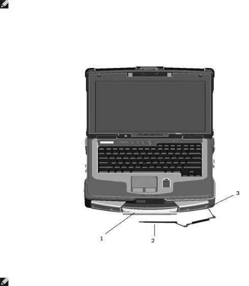
4Stylus, Tether and Clip (DirectVue Touch Screen Display option)
NOTE: Only Touch Screen Display configurations will include the stylus, stylus housing, tether and stylus clip. The Touch Screen Display is an optional feature.
If your XFR D630 is configured with the DirectVue Touch Screen Display, it will also be equipped with the optional stylus housing, stylus, stylus tether, and stylus clip.
To replace the stylus, stylus tether or stylus clip, follow the directions provided in the sections below.
1 |
Stylus housing |
2 |
Stylus and stylus tether |
3 |
Stylus clip (for connection to |
|
the notebook) |
||||||
|
|
|
|
|
NOTE: The stylus clip can be installed on either the left or right side of the handle to allow for right or left-handed use.
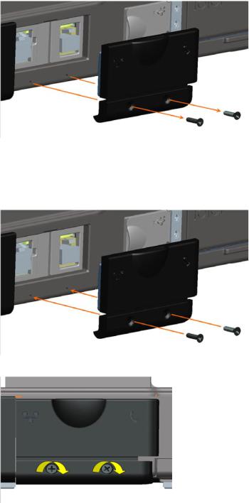
4.1 Replacing the Stylus Clip
Page 17 of 106 |
Revision A01 |

DellTM XFR D630 Fully Rugged Notebook Service Manual
The stylus clip is installed on the handle assembly’s end screw on the left or right side of the notebook. The stylus clip provides an eyelet into which the stylus tether can be routed to attach the stylus and stylus tether to the notebook
1 |
Handle cover |
2 |
Stylus clip |
3 |
Screw |
|
|
|
|
|
|
Close Up View of Installed Stylus Clip
CAUTION: Care is needed when installing this clip. The clip is installed with the raised part towards the center of the notebook so that the raised part of the clip is within the recessed area of the handle cover. If the clip is installed the opposite way, this raised metal part of the clip is now above the handle cover housing, and you can easily cut or injure yourself.
To replace the stylus clip:
1.Loosen the screw on the end of the handle cover that secures the stylus clip. Note that the stylus clip can be installed on the end of either handle cover to allow for right or left-handed use.
2.Slide the old stylus clip from beneath the loosened screw.
3.Slide the new stylus clip between the handle cover and the screw.
Page 18 of 106 |
Revision A01 |

DellTM XFR D630 Fully Rugged Notebook Service Manual
4. Tighten the screw, ensuring the screw head secures the stylus clip in place.
NOTE: If you relocate the stylus from one side of the handle to the other, remember to tighten the screw that was loosened in step 1.
NOTE: The stylus clip can be installed on either the left or right side of the handle to allow for right or left-handed use.
4.2 Replacing the Stylus
1 |
Stylus |
2 |
Stylus tether (with loops on each end) |
|
|
|
|
To replace the stylus:
1.Remove the tether and stylus from the stylus clip:
a.At the stylus clip, loosen the looped end of the tether.
b.Pull the stylus and tether through the loop until the tether is free from the stylus clip.
2.Remove the stylus from the tether:
a.At the stylus, loosen the looped end of the tether.
b.Pull the stylus and tether through the loop until the stylus is free from the tether.
3.Install the new stylus:
a.Place one of the looped ends of the tether through the hole in the end of the new stylus and then place the free end of the tether through the loop.
b.Pull the remainder of the tether through the loop until tight.
c.Your new stylus is now attached to the tether.
4.Attach the stylus and tether to the stylus clip:
a.Place the free end of the tether through the stylus clip.
b.Pull the stylus and tether through the loop until tight.
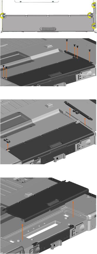
5 Handle
The XFR D630 is equipped with a factory installed handle. This section provides instructions for removing and installing the handle if replacement is required.
Page 19 of 106 |
Revision A01 |

DellTM XFR D630 Fully Rugged Notebook Service Manual
1 |
Main handle assembly |
2 |
Handle cover (2) |
|
|
|
|
5.1 |
Removing the Handle |
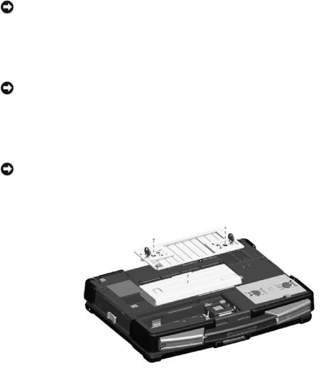
1. |
Remove the 4 screws (2 on each handle cover) that secure the handle covers as shown in the |
|
figure above. |
2. |
Remove the 6 screws (3 on each side) on the top of the handle assembly that secure the |
|
handle to the handle brackets. |
3. |
Remove the 6 screws (3 on each side) that secure the main handle assembly. |
5.2 |
Installing the Handle |
1.Align the main handle assembly with the mounting holes in the front plate of the XFR D630 as shown in the figure above.
2.Secure the main handle assembly to the XFR D630 using the 6 screws provided.
3.Install the 6 screws (3 on each side) on the top of the handle assembly that secure the handle to the handle brackets.
Page 20 of 106 |
Revision A01 |
DellTM XFR D630 Fully Rugged Notebook Service Manual
4.Align each of the handle covers over the main handle assembly ends as shown.
5.If your XFR D630 is equipped with the optional Touch Screen, please refer to Replacing the Stylus Clip for instructions regarding installing the stylus clip onto one side of the handle assembly.
6.Secure the handle covers over the main handle assembly and to the XFR D630 with the 4 screws provided (2 on each side).
6 Port Covers
The XFR D630 utilizes port covers to secure and protect the connectors and devices of the notebook.
6.1 Comms Door
The Comms Door is located on the notebook’s rear panel and protects the RJ-45 and RJ-11 connectors.
6.1.1Removing the Comms Door
1. Remove the 2 screws that secure the Comms Door.
2. Remove the Comms Door from the notebook.
Page 21 of 106 |
Revision A01 |
DellTM XFR D630 Fully Rugged Notebook Service Manual
6.1.2Installing the Comms Door
1. Align the Comms Door with the Comms Door mounting holes on the notebook.
2. Use the 2 screws to secure the Comms Door to the notebook.
6.2 Docking Door
The Docking Door is located on the bottom of the notebook, and protects the docking connector.
6.2.1Removing the Docking Door
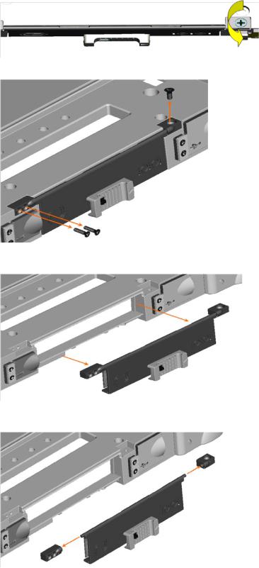
1. Remove the 6 screws that secure the Docking Door to the notebook. |
|
Page 22 of 106 |
Revision A01 |
DellTM XFR D630 Fully Rugged Notebook Service Manual
2. Remove the 2 brackets that secure the Docking Door.
3. Lift the Docking Door away from the notebook.
Page 23 of 106 |
Revision A01 |

DellTM XFR D630 Fully Rugged Notebook Service Manual
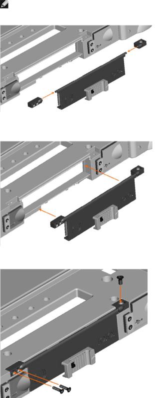
6.2.2Installing the Docking Door
1. Place the Docking Door onto the notebook aligning it with the 6 mounting holes.
2. Place the two mounting brackets onto the docking door (see figure below).
Page 24 of 106 |
Revision A01 |

DellTM XFR D630 Fully Rugged Notebook Service Manual
3. Secure the docking door with the 6 screws provided.
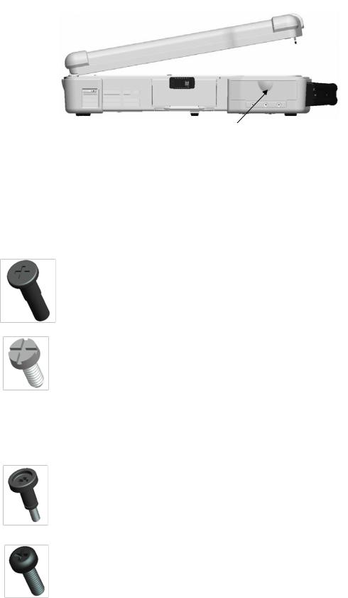
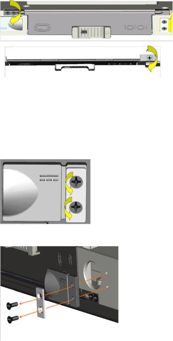
6.3 VGA Door
The VGA Door is located on the rear panel of the notebook, and protects the serial and video connectors.
6.3.1Removing the VGA Door
NOTE: The VGA Door is secured by 3 screws. To access all the screws the notebook must be turned over. When facing the VGA Door, the right screw is accessed from the top, and the 2 left screws are accessed from the front.
1.Turn the notebook top side down, to access the VGA Door on the rear panel of the notebook.
2.Remove the 3 screws that secure the VGA Door (one screw on the top right, the other 2 on the front left).
Page 25 of 106 |
Revision A01 |
DellTM XFR D630 Fully Rugged Notebook Service Manual
3. Remove the VGA Door from the notebook.
4. Remove the 2 screw mounts from the VGA Door hinge and set aside for later use.
Page 26 of 106 |
Revision A01 |
DellTM XFR D630 Fully Rugged Notebook Service Manual
6.3.2Installing the VGA Door
1. Place the 2 screw mounts on the VGA Door hinge.
NOTE: Be careful to ensure that the single screw mount is placed on the right side of the hinge, while the 2 screw mount is placed on the left side of the hinge.
2.Place the VGA Door and screw mounts onto the notebook and align with the mounting holes provided.
3. Secure the VGA Door to the notebook, using the 3 screws provided.
Page 27 of 106 |
Revision A01 |
DellTM XFR D630 Fully Rugged Notebook Service Manual
6.4 Power Door
The Power Door is located on the rear panel of the notebook, and protects the notebook’s power connector.
6.4.1Removing the Power Door
1.Remove the 2 screws that secure the Power Door to the notebook.
2.Remove the screw plate and the Power Door from the notebook.
6.4.2Installing the Power Door
1.Align the Power Door and the screw plate with the screw holes provided on the rear panel for the Power Door.
Page 28 of 106 |
Revision A01 |

DellTM XFR D630 Fully Rugged Notebook Service Manual
2.Use the 2 screws provided to secure the screw plate and Power Door to the notebook.
6.5XBay Door
6.5.1Removing the XBay Door
The XBay Door is located on the notebook’s right side, and protects the notebook’s optical drive.
1. Turn the notebook top side down, and remove the 2 screws that secure the XBay Door.
Page 29 of 106 |
Revision A01 |

DellTM XFR D630 Fully Rugged Notebook Service Manual
2. Remove the XBay Door from the notebook.
6.5.2Installing the XBay Door
1. Place the XBay Door onto the notebook, aligning it with the 2 screw mount holes.
Page 30 of 106 |
Revision A01 |
 Loading...