


Dell™ Inspiron™ One 2305/2310 Service Manual
Technical Overview |
Memory Module(s) |
Before You Begin |
Wireless Mini-Card(s) |
Back Cover |
Coin-Cell Battery |
Hard Drive |
MXM-Assembly Fan (Optional) |
Optical Drive |
MXM Assembly (Optional) |
Converter Card |
Processor Heat-Sink Fan |
Touch Screen Control Card (Optional) |
Processor Heat-Sink |
Front Stand |
Processor |
Audio Video Board Shield |
Speakers |
Audio Video Board |
Speaker Cover |
Audio Video Board Cable |
System Board |
Audio Video Button Board |
Internal Card With Bluetooth® Wireless Technology |
Rear Stand Cover |
Camera Module |
Rear Stand |
Infrared Card |
Middle Frame |
B-CAS Card (Optional) |
System-Board Shield |
Display |
Antenna-In Connector |
System Setup Utility |
Infrared Blaster Connector |
Flashing the BIOS |
Wireless Antenna |
|
|
|
Notes, Cautions, and Warnings
NOTE: A NOTE indicates important information that helps you make better use of your computer.
CAUTION: A CAUTION indicates either potential damage to hardware or loss of data and tells you how to avoid the problem. WARNING: A WARNING indicates a potential for property damage, personal injury, or death.
Information in this document is subject to change without notice.
© 2010 Dell Inc. All rights reserved.
Reproduction of these materials in any manner whatsoever without the written permission of Dell Inc. is strictly forbidden.
Trademarks used in this text: Dell, the DELL logo, and Inspiron are trademarks of Dell Inc.; Bluetooth is a registered trademark owned by Bluetooth SIG, Inc. and is used by Dell under license; Microsoft, Windows, and the Windows start button logo are either trademarks or registered trademarks of Microsoft Corporation in the United States and/or other countries.
Other trademarks and trade names may be used in this document to refer to either the entities claiming the marks and names or their products. Dell Inc. disclaims any proprietary interest in trademarks and trade names other than its own.
August 2010 Rev. A00
Regulatory model: W01C series Regulatory type: W01C001; W01C002
Back to Contents Page
Audio Video Board
Dell™ Inspiron™ One 2305/2310 Service Manual
Removing the Audio Video (AV) Board
Replacing the Audio Video (AV) Board
WARNING: Before working inside your computer, read the safety information that shipped with your computer. For additional safety best practices information, see the Regulatory Compliance Homepage at www.dell.com/regulatory_compliance.
CAUTION: Only a certified service technician should perform repairs on your computer. Damage due to servicing that is not authorized by Dell™ is not covered by your warranty.
CAUTION: To avoid electrostatic discharge, ground yourself by using a wrist grounding strap or by periodically touching an unpainted metal surface (such as a connector on your computer).
Removing the Audio Video (AV) Board
1.Follow the instructions in Before You Begin.
2.Remove the back cover (see Removing the Back Cover).
3.Follow the instructions from step 2 to step 5 in Removing the Front Stand.
4.Remove the AV board shield (see Removing the Audio Video (AV) Board Shield).
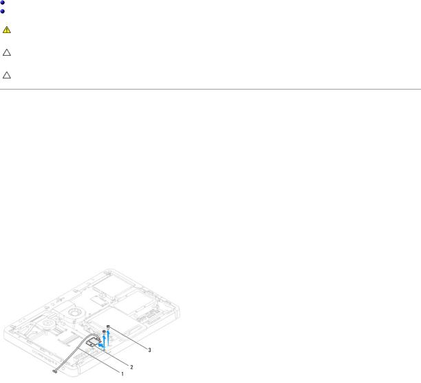
5.Disconnect the AV board cables from the connectors on the AV board.
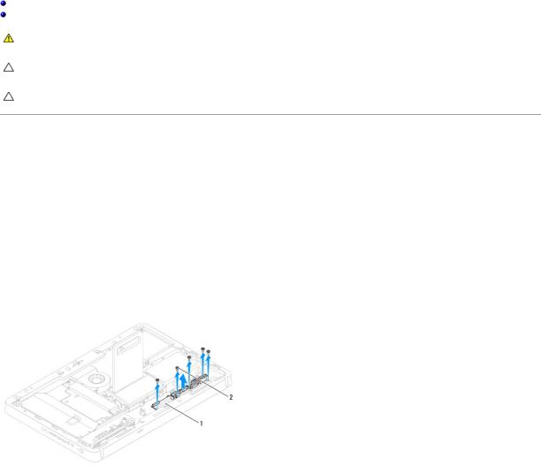
6.Remove the five screws that secure the AV board to the chassis.
7.Lift the AV board away from the chassis.
1 |
AV board |
2 |
screws (5) |
|
|
|
|
|
|
|
|
|
|
|
Replacing the Audio Video (AV) Board
1.Follow the instructions in Before You Begin.
2.Align the screw holes on the AV board with the screw holes on the chassis.
3.Replace the five screws that secure the AV board to the chassis.
4.Connect the AV board cables to the connectors on the AV board.
5.Replace the AV board shield (see Replacing the Audio Video (AV) Board Shield).
6.Follow the instructions from step 4 to step 5 in Replacing the Front Stand.
7.Replace the back cover (see Replacing the Back Cover).

CAUTION: Before turning on the computer, replace all screws and ensure that no stray screws remain inside the computer. Failure to do so may result in damage to the computer.
8. Connect your computer and all attached devices to electrical outlets, and turn them on.
Back to Contents Page
Back to Contents Page
Audio Video Board Shield
Dell™ Inspiron™ One 2305/2310 Service Manual
Removing the Audio Video (AV) Board Shield
Replacing the Audio Video (AV) Board Shield
WARNING: Before working inside your computer, read the safety information that shipped with your computer. For additional safety best practices information, see the Regulatory Compliance Homepage at www.dell.com/regulatory_compliance.
CAUTION: Only a certified service technician should perform repairs on your computer. Damage due to servicing that is not authorized by Dell™ is not covered by your warranty.
CAUTION: To avoid electrostatic discharge, ground yourself by using a wrist grounding strap or by periodically touching an unpainted metal surface (such as a connector on your computer).
Removing the Audio Video (AV) Board Shield
1.Follow the instructions in Before You Begin.
2.Remove the back cover (see Removing the Back Cover).
3.Follow the instructions from step 2 to step 5 in Removing the Front Stand.
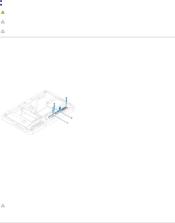
4.Remove the three screws that secure the AV board shield to the chassis.
5.Lift the AV board shield away from the chassis.
1 |
AV-board shield |
2 |
screws (3) |
|
|
|
|
|
|
|
|
|
|
|
Replacing the Audio Video (AV) Board Shield
1.Follow the instructions in Before You Begin.
2.Align the screw holes on the AV board shield with the screw holes on the chassis.
3.Replace the three screws that secure the AV board shield to the chassis.
4.Follow the instructions from step 4 to step 5 in Replacing the Front Stand.
5.Replace the back cover (see Replacing the Back Cover).
CAUTION: Before turning on the computer, replace all screws and ensure that no stray screws remain inside the computer. Failure to do so may result in damage to the computer.
6. Connect your computer and all attached devices to electrical outlets, and turn them on.
Back to Contents Page

Back to Contents Page
Audio Video Board Cable
Dell™ Inspiron™ One 2305/2310 Service Manual
Removing the Audio Video (AV) Board Cable
Replacing the Audio Video (AV) Board Cable
WARNING: Before working inside your computer, read the safety information that shipped with your computer. For additional safety best practices information, see the Regulatory Compliance Homepage at www.dell.com/regulatory_compliance.
CAUTION: Only a certified service technician should perform repairs on your computer. Damage due to servicing that is not authorized by Dell™ is not covered by your warranty.
CAUTION: To avoid electrostatic discharge, ground yourself by using a wrist grounding strap or by periodically touching an unpainted metal surface (such as a connector on your computer).
Removing the Audio Video (AV) Board Cable
1.Follow the instructions in Before You Begin.
2.Remove the back cover (see Removing the Back Cover).
3.Follow the instructions from step 2 to step 5 in Removing the Front Stand.
4.Remove the AV board shield (see Removing the Audio Video (AV) Board Shield).
5.Disconnect the AV board cable from the connector on the AV Board.
1 |
AV board cable |
|
|
6.Remove the AV board (see Removing the Audio Video (AV) Board).
7.Remove the system board (see Removing the System Board).
8.Remove the display panel (see Removing the Display Panel).
9.Make note of the AV board cable routing and release the cable from the securing tapes.
10.Remove the AV board cable from the routing guide.
Replacing the Audio Video (AV) Board Cable
1.Follow the instructions in Before You Begin.
2.Route the AV board cable through the routing guide and secure it with the tapes.
3.Replace the system board (see Replacing the System Board).
4.Replace the display panel (see Replacing the Display Panel).

5.Replace the AV board (see Replacing the Audio Video (AV) Board).
6.Connect the AV board cable to the connector on the AV board.
7.Replace the AV board shield (see Replacing the Audio Video (AV) Board Shield).
8.Follow the instructions from step 4 to step 5 in Replacing the Front Stand.
9.Replace the back cover (see Replacing the Back Cover).
CAUTION: Before turning on the computer, replace all screws and ensure that no stray screws remain inside the computer. Failure to do so may result in damage to the computer.
10. Connect your computer and all attached devices to electrical outlets, and turn them on.
Back to Contents Page
Back to Contents Page
Audio Video Button Board
Dell™ Inspiron™ One 2305/2310 Service Manual
Removing the Audio Video (AV) Button Board
Replacing the Audio Video (AV) Button Board
WARNING: Before working inside your computer, read the safety information that shipped with your computer. For additional safety best practices information, see the Regulatory Compliance Homepage at www.dell.com/regulatory_compliance.
CAUTION: Only a certified service technician should perform repairs on your computer. Damage due to servicing that is not authorized by Dell™ is not covered by your warranty.
CAUTION: To avoid electrostatic discharge, ground yourself by using a wrist grounding strap or by periodically touching an unpainted metal surface (such as a connector on your computer).
Removing the Audio Video (AV) Button Board
1.Follow the instructions in Before You Begin.
2.Remove the back cover (see Removing the Back Cover).
3.Follow the instructions from step 2 to step 5 in Removing the Front Stand.
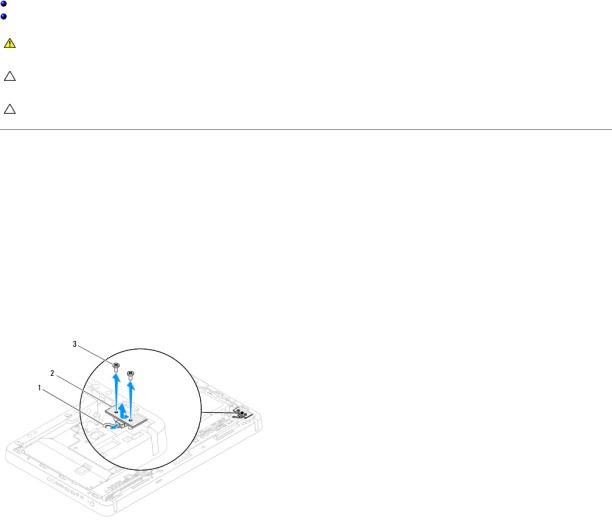
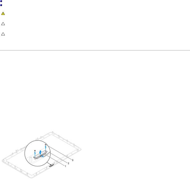
4.Disconnect the AV button board cable from the connector on the AV button board.
5.Remove the two screws that secure the AV button board to the chassis.
6.Carefully slide and lift the AV button board away from the computer.
1 |
AV button board cable |
2 |
AV button board |
|
|
|
|
|
|
3 |
screws (2) |
|
|
|
|
|
|
|
|
Replacing the Audio Video (AV) Button Board
1.Follow the instructions in Before You Begin.
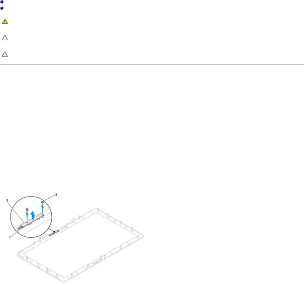
2.Gently slide the AV button board into the slot on the middle frame.
3.Align the screw holes on the AV button board with the screw holes on the chassis
4.Replace the two screws that secure the AV button board to the chassis.
5.Connect the AV button board cable to the connector on the AV button board.
6.Follow the instructions from step 4 to step 5 in Replacing the Front Stand.

7. Replace the back cover (see Replacing the Back Cover).
CAUTION: Before turning on the computer, replace all screws and ensure that no stray screws remain inside the computer. Failure to do so may result in damage to the computer.
8. Connect your computer and all attached devices to electrical outlets, and turn them on.
Back to Contents Page
Back to Contents Page
Back Cover
Dell™ Inspiron™ One 2305/2310 Service Manual
Removing the Back Cover
Replacing the Back Cover
WARNING: Before working inside your computer, read the safety information that shipped with your computer. For additional safety best practices information, see the Regulatory Compliance Homepage at www.dell.com/regulatory_compliance.
CAUTION: Only a certified service technician should perform repairs on your computer. Damage due to servicing that is not authorized by Dell™ is not covered by your warranty.
CAUTION: To avoid electrostatic discharge, ground yourself by using a wrist grounding strap or by periodically touching an unpainted metal surface (such as a connector on your computer).
CAUTION: Ensure that sufficient space exists to support the computer with the computer cover removed—at least 30 cm (1 ft.) of desk top space.
Removing the Back Cover
1. Follow the instructions in Before You Begin.
CAUTION: Before opening your computer, ensure that you place the computer on a soft cloth or clean surface to avoid any scratches on the display.
2.Place the computer face down on a flat surface.
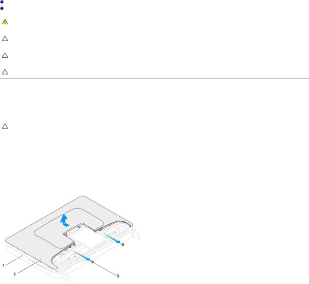
3.Remove the two screws that secure the back cover to the computer.
4.Slide and lift the back cover off the computer.
5.Place the back cover in a secure location.
1 |
middle frame |
2 |
back cover |
|
|
|
|
|
|
3 |
screws (2) |
|
|
|
|
|
|
|
|
|
|
|
|
|
Replacing the Back Cover
1.Follow the instructions in Before You Begin.
2.Align the tabs on the back cover with the slots on the middle frame and then slide the back cover into place.
3.Replace the two screws that secure the back cover to the computer.
4.Place the computer in an upright position.
CAUTION: Before turning on the computer, replace all screws and ensure that no stray screws remain inside the computer. Failure to do so may result in damage to the computer.
5. Connect your computer and all attached devices to electrical outlets, and turn them on.
Back to Contents Page
Back to Contents Page
B-CAS Card (Optional)
Dell™ Inspiron™ One 2305/2310 Service Manual
Removing the B-CAS Card
Replacing the B-CAS Card
WARNING: Before working inside your computer, read the safety information that shipped with your computer. For additional safety best practices information, see the Regulatory Compliance Homepage at www.dell.com/regulatory_compliance.
CAUTION: Only a certified service technician should perform repairs on your computer. Damage due to servicing that is not authorized by Dell™ is not covered by your warranty.
CAUTION: To avoid electrostatic discharge, ground yourself by using a wrist grounding strap or by periodically touching an unpainted metal surface (such as a connector on your computer).
Removing the B-CAS Card
1.Follow the instructions in Before You Begin.
2.Remove the back cover (see Removing the Back Cover).
3.Follow the instructions from step 2 to step 5 in Removing the Front Stand.
4.Remove the system-board shield (see Removing the System-Board Shield).
5.Remove the two screws that secure the B-CAS card to the chassis.
6.Carefully slide the B-CAS card out of the B-CAS card location.
7.Disconnect the B-CAS-card cable from the connector on the TV tuner card.
8.Lift the B-CAS card away from the computer.
1 |
B-CAS-card cable |
2 |
B-CAS card |
|
|
|
|
|
|
3 |
screws (2) |
|
|
|
|
|
|
|
|
|
|
|
|
|
Replacing the B-CAS Card
1.Follow the instructions in Before You Begin.
2.Connect the B-CAS-card cable to the connector on the TV tuner card.
3.Carefully slide the B-CAS card into the B-CAS card location.
4.Align the screw holes on the B-CAS card with the screw holes on the chassis.
5.Replace the two screws that secure the B-CAS card to the chassis.

6.Replace the system-board shield (see Removing the System-Board Shield).
7.Follow the instructions from step 4 to step 5 in Replacing the Front Stand.
8.Replace the back cover (see Replacing the Back Cover).
CAUTION: Before turning on the computer, replace all screws and ensure that no stray screws remain inside the computer. Failure to do so may result in damage to the computer.
9. Connect your computer and all attached devices to electrical outlets, and turn them on.
Back to Contents Page

Back to Contents Page
Before You Begin
Dell™ Inspiron™ One 2305/2310 Service Manual
Recommended Tools
Turning Off Your Computer
Safety Instructions
This manual provides procedures for removing and installing the components in your computer. Unless otherwise noted, each procedure assumes that the following conditions exist:
•You have performed the steps in Turning Off Your Computer and Safety Instructions.
•You have read the safety information that shipped with your computer.
•A component can be replaced or—if purchased separately—installed by performing the removal procedure in reverse order.
Recommended Tools
The procedures in this document may require the following tools:
•Small Phillips screwdriver
•Hex nut driver
•Flash BIOS executable update program available at support.dell.com
Turning Off Your Computer
CAUTION: To avoid losing data, save and close all open files and exit all open programs before you turn off your computer.
1.Save and close all open files and exit all open programs.
2.To shut down the operating system, click Start  and then click Shut Down.
3.Ensure that the computer is turned off. If your computer did not automatically turn off when you shut down the operating system, press and hold the power button until the computer turns off.
Safety Instructions
Use the following safety guidelines to help protect your computer from potential damage and to help to ensure your own personal safety.
WARNING: Before working inside your computer, read the safety information that shipped with your computer. For additional safety best practices information, see the Regulatory Compliance Homepage at www.dell.com/regulatory_compliance.
WARNING: Disconnect all power sources before opening the enclosure to replace, remove, or install accessories. After the installation is completed, the enclosure must be replaced and all fasteners installed before connecting to the power source.
CAUTION: Only a certified service technician is authorized to remove the computer cover and access any of the components inside the computer. See the safety instructions for complete information about safety precautions, working inside your computer, and protecting against electrostatic discharge.
CAUTION: To avoid electrostatic discharge, ground yourself by using a wrist grounding strap or by periodically touching an unpainted metal surface (such as a connector on your computer).
CAUTION: When you disconnect a cable, pull on its connector or on its pull-tab, not on the cable itself. Some cables have connectors with locking tabs; if you are disconnecting this type of cable, press in on the locking tabs before you disconnect the cable. As you pull connectors apart, keep them evenly aligned to avoid bending any connector pins. Also, before you connect a cable, ensure that both connectors are correctly oriented and aligned.
CAUTION: To avoid damaging the computer, perform the following steps before you begin working inside the computer.
1.Ensure that the work surface is flat and clean to prevent the computer display from being scratched.
2.Turn off your computer (see Turning Off Your Computer) and all attached devices.

CAUTION: To disconnect a network cable, first unplug the cable from your computer and then unplug the cable from the network device.
3.Disconnect all telephone or network cables from the computer.
4.Disconnect your computer and all attached devices from their electrical outlets.
5.Disconnect all attached devices from your computer.
6.Press and hold the power button while the computer is unplugged to ground the system board.
CAUTION: Before touching anything inside your computer, ground yourself by touching an unpainted metal surface, such as the metal at the back of the computer. While you work, periodically touch an unpainted metal surface to dissipate static electricity, which could harm internal components.
Back to Contents Page

Back to Contents Page
Flashing the BIOS
Dell™ Inspiron™ One 2305/2310 Service Manual
The BIOS may require flashing when an update is available or when replacing the system board. To flash the BIOS:
1.Turn on the computer.
2.Go to support.dell.com/support/downloads.
3.Locate the BIOS update file for your computer:
NOTE: The Service Tag for your computer is located on a label at the back of your computer.
If you have your computer's Service Tag:
a.Click Enter a Service Tag.
b.Enter your computer's Service Tag in the Enter a service tag: field, click Go, and proceed to step 4.
If you do not have your computer's Service Tag:
a.Click Select Model.
b.Select the type of product in the Select Your Product Family list.
c.Select the product brand in the Select Your Product Line list.
d.Select the product model number in the Select Your Product Model list.
NOTE: If you have selected a different model and want to start over again, click Start Over on the top right of the menu.
e.Click Confirm.
4.A list of results appear on the screen. Click BIOS.
5.Click Download Now to download the latest BIOS file. The File Download window appears.
6.Click Save to save the file on your desktop. The file downloads to your desktop.
7.Click Close if the Download Complete window appears.
The file icon appears on your desktop and is titled the same as the downloaded BIOS update file.
8.Double-click the file icon on the desktop and follow the instructions on the screen.
Back to Contents Page
Back to Contents Page
Internal Card With Bluetooth® Wireless Technology
Dell™ Inspiron™ One 2305/2310 Service Manual
Removing the Bluetooth Card
Replacing the Bluetooth Card
WARNING: Before working inside your computer, read the safety information that shipped with your computer. For additional safety best practices information, see the Regulatory Compliance Homepage at www.dell.com/regulatory_compliance.
CAUTION: Only a certified service technician should perform repairs on your computer. Damage due to servicing that is not authorized by Dell™ is not covered by your warranty.
CAUTION: To avoid electrostatic discharge, ground yourself by using a wrist grounding strap or by periodically touching an unpainted metal surface (such as a connector on your computer).
If you ordered a card with Bluetooth wireless technology with your computer, it is already installed.
Removing the Bluetooth Card
1.Follow the instructions in Before You Begin.
2.Remove the system board (see Removing the System Board).
3.Follow the instructions from step 5 to step 11 in Removing the Display Bezel.
4.Turn the display bezel over.
5.Remove the mylar sleeve from the Bluetooth card.
6.Remove the two screws that secure the Bluetooth card to the display bezel.
7.Disconnect the Bluetooth-card cable from the connector on the Bluetooth card.
8.Lift the Bluetooth card away from the display bezel.
1 |
Bluetooth card |
2 |
Bluetooth-card cable |
|
|
|
|
|
|
3 |
screws (2) |
|
|
|
|
|
|
|
|
|
|
|
|
|
Replacing the Bluetooth Card
1.Follow the instructions in Before You Begin.
2.Connect the Bluetooth-card cable to the connector on the Bluetooth card.
3.Align the screw holes on the Bluetooth card with the screw holes on the display bezel.
4.Replace the two screws that secure the Bluetooth card to the display bezel.

5.Turn the display bezel over.
6.Follow the instructions from step 2 to step 12 in Replacing the Display Bezel.
7.Replace the system board (See Replacing the System Board).
CAUTION: Before turning on the computer, replace all screws and ensure that no stray screws remain inside the computer. Failure to do so may result in damage to the computer.
8. Connect your computer and all attached devices to electrical outlets, and turn them on.
Back to Contents Page
Back to Contents Page
Camera Module
Dell™ Inspiron™ One 2305/2310 Service Manual
Removing the Camera Module
Replacing the Camera Module
WARNING: Before working inside your computer, read the safety information that shipped with your computer. For additional safety best practices information, see the Regulatory Compliance Homepage at www.dell.com/regulatory_compliance.
CAUTION: Only a certified service technician should perform repairs on your computer. Damage due to servicing that is not authorized by Dell™ is not covered by your warranty.
CAUTION: To avoid electrostatic discharge, ground yourself by using a wrist grounding strap or by periodically touching an unpainted metal surface (such as a connector on your computer).
Removing the Camera Module
1.Follow the instructions in Before You Begin.
2.Remove the system board (see Removing the System Board).
3.Follow the instructions from step 5 to step 11 in Removing the Display Bezel.
4.Turn the display bezel over.
5.Remove the mylar sleeve from the Bluetooth card.
6.Remove the two screws that secure the camera module to the display bezel.
7.Disconnect the camera cable from the connector on the camera module.
8.Lift the camera module off the display bezel.
1 |
camera cable connector |
2 |
camera module |
|
|
|
|
|
|
3 |
screws (2) |
|
|
|
|
|
|
|
|
|
|
|
|
|
Replacing the Camera Module
1.Follow the instructions in Before You Begin.
2.Align the screw holes on the camera module with the screw holes on the display bezel.
3.Replace the two screws that secure the camera module to the display bezel.
4.Replace the mylar sleeve on the Bluetooth card.

5.Turn the display bezel over.
6.Follow the instructions from step 2 to step 12 in Replacing the Display Bezel.
7.Replace the system board (See Replacing the System Board).
CAUTION: Before turning on the computer, replace all screws and ensure that no stray screws remain inside the computer. Failure to do so may result in damage to the computer.
8. Connect your computer and all attached devices to electrical outlets, and turn them on.
Back to Contents Page
Back to Contents Page
Wireless Mini-Card(s)
Dell™ Inspiron™ One 2305/2310 Service Manual
Removing the Mini-Card(s)
Replacing the Mini-Card(s)
WARNING: Before working inside your computer, read the safety information that shipped with your computer. For additional safety best practices information, see the Regulatory Compliance Homepage at www.dell.com/regulatory_compliance.
CAUTION: Only a certified service technician should perform repairs on your computer. Damage due to servicing that is not authorized by Dell™ is not covered by your warranty.
CAUTION: To avoid electrostatic discharge, ground yourself by using a wrist grounding strap or by periodically touching an unpainted metal surface (such as a connector on your computer).
CAUTION: When the Mini-Card is not in the computer, store it in protective antistatic packaging (see "Protecting Against Electrostatic Discharge" in the safety instructions that shipped with your computer).
NOTE: Dell does not guarantee compatibility or provide support for Mini-Cards from sources other than Dell.
If you ordered a wireless Mini-Card with your computer, the card is already installed.
Your computer supports two half Mini-Card slots for Wireless Local Area Network (WLAN) and a TV tuner module.
Removing the Mini-Card(s)
1.Follow the instructions in Before You Begin.
2.Remove the back cover (see Removing the Back Cover).
3.Follow the instructions from step 2 to step 5 in Removing the Front Stand.
4.Remove the system-board shield (see Removing the System-Board Shield).
5.Disconnect the antenna cable(s) from the Mini-Card.
1 |
antenna cables (2) |
6.Remove the two screws that secure the Mini-Card to the system-board connector.
7.Lift the Mini-Card away from the system-board connector.
CAUTION: When the Mini-Card is not in the computer, store it in protective antistatic packaging (see "Protecting Against Electrostatic Discharge" in the safety instructions that shipped with your computer).
1 |
Mini-Card |
2 |
system board connector |
|
3 |
screws (2) |
|
|
|
|
|
|
|
|
|
|
|
|
|

Replacing the Mini-Card(s)
CAUTION: The connectors are keyed to ensure correct insertion. Use of excessive force may damage the connectors.
CAUTION: To avoid damage to the Mini-Card, ensure that there are no cables or antenna cables under the Mini-Card.
1.Follow the instructions in Before You Begin.
2.Align the notch on the Mini-Card with the tab in the system-board connector.
3.Insert the Mini-Card at a 45-degree angle into the system-board connector.
4.Press the other end of the Mini-Card down and replace the two screws that secure the Mini-Card to the system-board connector.
5.Connect the appropriate antenna cable(s) to the Mini-Card you are installing. The following table provides the antenna cable color scheme for the MiniCard(s) supported by your computer.
Connectors on the Mini-Card |
Antenna Cable Color Scheme |
WLAN (2 antenna cables) |
|
Main WLAN (white triangle) |
white |
Auxiliary WLAN (black triangle) |
black |
|
|
TV tuner (1 antenna cable) |
black |
|
|
6.Replace the system-board shield (see Replacing the System-Board Shield).
7.Follow the instructions from step 4 to step 5 in Replacing the Front Stand.
8.Replace the back cover (see Replacing the Back Cover).
CAUTION: Before turning on the computer, replace all screws and ensure that no stray screws remain inside the computer. Failure to do so may result in damage to the computer.
9. Connect your computer and all attached devices to electrical outlets, and turn them on.
Back to Contents Page
Back to Contents Page
Coin-Cell Battery
Dell™ Inspiron™ One 2305/2310 Service Manual
Removing the Coin-Cell Battery
Replacing the Coin-Cell Battery
WARNING: Before working inside your computer, read the safety information that shipped with your computer. For additional safety best practices information, see the Regulatory Compliance Homepage at www.dell.com/regulatory_compliance.
WARNING: A new battery can explode if it is incorrectly installed. Replace the battery only with the same or equivalent type recommended by the manufacturer. Discard used batteries according to the manufacturer's instructions.
CAUTION: Only a certified service technician should perform repairs on your computer. Damage due to servicing that is not authorized by Dell™ is not covered by your warranty.
CAUTION: To avoid electrostatic discharge, ground yourself by using a wrist grounding strap or by periodically touching an unpainted metal surface (such as a connector on your computer).
Removing the Coin-Cell Battery
1.Record all the screens in system setup utility (see System Setup Utility) so that you can restore the correct settings in step 7.
2.Follow the instructions in Before You Begin.
3.Remove the back cover (see Removing the Back Cover).
4.Follow the instructions from step 2 to step 5 in Removing the Front Stand.
5.Remove the system-board shield (see Removing the System-Board Shield).
6.Locate the battery socket (see System Board Components).
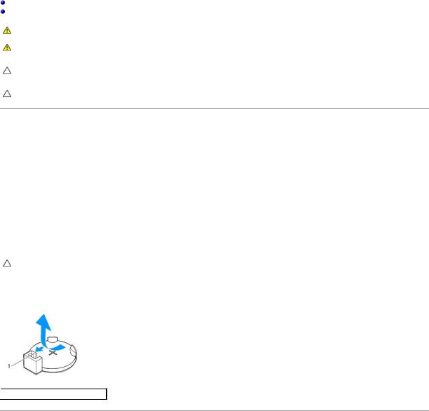
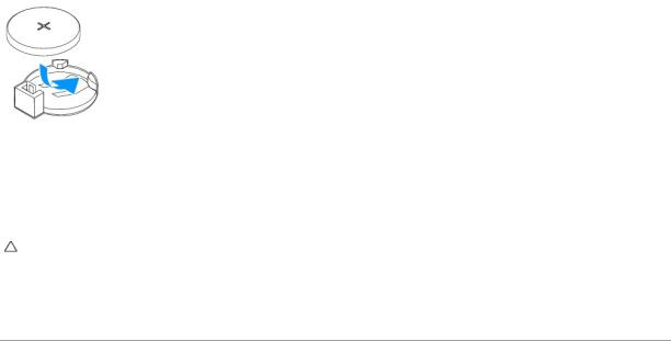
CAUTION: If you pry the battery out of its socket with a blunt object, be careful not to touch the system board with the object. Ensure that the object is inserted between the battery and the socket before you attempt to pry out the battery. Otherwise, you may damage the system board by prying off the socket or by breaking circuit traces on the system board.
7. Press the battery release lever to remove the battery.
 1
1  battery release lever
Replacing the Coin-Cell Battery
1.Follow the instructions in Before You Begin.
2.Insert the new battery (CR2032) into the socket with the side labeled "+" facing up, and press the battery into place.
3.Replace the system-board shield (see Replacing the System-Board Shield).
4.Follow the instructions from step 4 to step 5 in Replacing the Front Stand.
5.Replace the back cover (see Replacing the Back Cover).
CAUTION: Before turning on the computer, replace all screws and ensure that no stray screws remain inside the computer. Failure to do so may result in damage to the computer.
6.Connect your computer and devices to electrical outlets, and then turn them on.
7.Enter the system setup utility (see System Setup Utility) and restore the settings you recorded in step 1.
Back to Contents Page

Back to Contents Page
Display
Dell™ Inspiron™ One 2305/2310 Service Manual
Display Bezel
Display Panel
Display Cable
WARNING: Before working inside your computer, read the safety information that shipped with your computer. For additional safety best practices information, see the Regulatory Compliance Homepage at www.dell.com/regulatory_compliance.
CAUTION: Only a certified service technician should perform repairs on your computer. Damage due to servicing that is not authorized by Dell™ is not covered by your warranty.
CAUTION: To avoid electrostatic discharge, ground yourself by using a wrist grounding strap or by periodically touching an unpainted metal surface (such as a connector on your computer).
Display Bezel
Removing the Display Bezel
1.Follow the instructions in Before You Begin.
2.Remove the AV board (see Removing the Audio Video (AV) Board).
3.Remove the middle frame (see Removing the Middle Frame).
4.Remove the system board (see Removing the System Board).
5.Remove the 18 screws that secure the display bezel to the chassis.
6.Carefully peel the silver foil that adheres the camera module to the chassis.
7.Make a note of the camera cable, infrared-card cable, and Bluetooth®-card cable routing and release the cables through the slots on the chassis.
8.Release the three tabs that secure the display bezel to the chassis.
9.Turn the computer over.
10.Using your fingertips, carefully pry up the inside edge of the display bezel.
11.Lift the display bezel away from the computer.
12.Remove the camera module (see Removing the Camera Module).
13.Remove the infrared card (see Removing the Infrared Card).
14.Remove the Bluetooth card (see Removing the Bluetooth Card).

1 |
display bezel |
2 |
screws (18) |
3 |
tabs (3) |
|
|
|
|
|
|
Replacing the Display Bezel
1.Follow the instructions in Before You Begin.
2.Replace the Bluetooth card (see ).
3.Replace the infrared card (see Replacing the Infrared Card).
4.Replace the camera module (see Replacing the Camera Module).
5.Slide the camera cable, infrared cable, and Bluetooth cable through the slots on the chassis.
6.Align the display bezel over the display and gently snap the display bezel into place.
7.Turn the computer over.
8.Ensure that the three tabs on the display bezel are secured to the slots on the chassis.
9.Route the camera cable, infrared cable, and Bluetooth cable through the routing guides.
10.Adhere the silver foil that secures the camera module to the chassis.
11.Replace the 18 screws that secure the display bezel to the chassis.
12.Replace the middle frame (See Replacing the Middle Frame).
13.Replace the system board (See Replacing the System Board).
14.Replace the AV board (See Replacing the Audio Video (AV) Board).
CAUTION: Before turning on the computer, replace all screws and ensure that no stray screws remain inside the computer. Failure to do so may result in damage to the computer.
15. Connect your computer and all attached devices to electrical outlets, and turn them on.
Display Panel
Removing the Display Panel
1.Follow the instructions in Before You Begin.
2.Follow the instructions from step 4 to step 11 in Removing the Display Bezel.
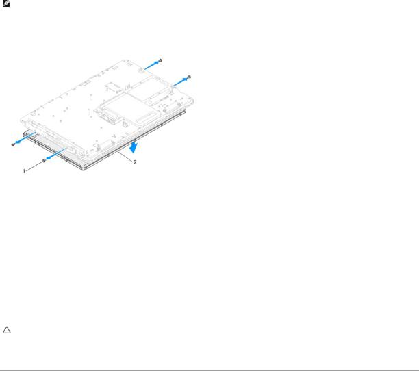
3.Remove the four screws that secure the display panel to the chassis.
NOTE: The number of screws that secure the display panel to the chassis may vary.
4.Remove the display cables, touch screen cables, and display panel power cable from the routing guides on the chassis.
5.Remove the display panel off the chassis.
1 |
screws (4) |
2 |
display panel |
|
|
|
|
Replacing the Display Panel
1.Follow the instructions in Before You Begin.
2.Route the display cables, touch screen cables, and display panel power cable through the routing guides on the chassis.
3.Align the screw holes on the display panel with the screw holes on the chassis and replace the four screws.
4.Follow the instructions from step 2 to step 13 in Replacing the Display Bezel.
CAUTION: Before turning on the computer, replace all screws and ensure that no stray screws remain inside the computer. Failure to do so may result in damage to the computer.
5. Connect your computer and all attached devices to electrical outlets, and turn them on.
Display Cable
Removing the Display Cable
1.Follow the instructions in Before You Begin.
2.Remove the display panel (see Removing the Display Panel).
3.Turn the display panel over.
4.Using the pull tab on the display cable, disconnect the display cable from the connector on the display panel.
 Loading...