


Dell™ Latitude™ D830 Service Manual
Before You Begin
Internal Card with Bluetooth® Wireless Technology
Hard Drive
Memory
FCM (Flash Cache Module)
Coin-Cell Battery
Hinge Cover
Keyboard
Communications Cards
Using Cards
PC Card Reader
Display Assembly
Palm Rest
Fan
Processor Thermal-Cooling Assembly
Processor Module
System Board
Base
Modem
Battery Latch
Flashing the BIOS
Pin Assignments for I/O Connectors
Notes, Notices, and Cautions
NOTE: A NOTE indicates important information that helps you make better use of your computer.
NOTICE: A NOTICE indicates either potential damage to hardware or loss of data and tells you how to avoid the problem. CAUTION: A CAUTION indicates a potential for property damage, personal injury, or death.
Information in this document is subject to change without notice.
© 2007 Dell Inc. All rights reserved.
Reproduction in any manner whatsoever without the written permission of Dell Inc. is strictly forbidden.
Trademarks used in this text: Dell, the DELL logo, and Latitude are trademarks of Dell Inc.; Bluetooth is a registered trademark owned by Bluetooth SIG, Inc. and is used by Dell under license.
Other trademarks and trade names may be used in this document to refer to either the entities claiming the marks and names or their products. Dell Inc. disclaims any proprietary interest in trademarks and trade names other than its own.
September 2009 Model PP04X Rev. A01

Back to Contents Page
Base
Dell™ Latitude™ D830 Service Manual
CAUTION: Before performing the following procedures, follow the safety instructions in the Product Information Guide.
NOTICE: To avoid electrostatic discharge, ground yourself by using a wrist grounding strap or by periodically touching a connector on the back panel of the computer.
1.Follow the procedures in Before You Begin.
2.Remove the hard drive (see Hard Drive).
3.Remove the hinge cover (see Hinge Cover).
4.Remove the internal card with Bluetooth® wireless technology.
5.Remove the keyboard (see Keyboard).
6.Remove the display assembly (see Removing the Display Assembly).
7.Remove the palm rest (see Palm Rest).
8.Remove the processor thermal-cooling assembly (see Processor Thermal-Cooling Assembly).
9.Remove the processor (see Removing the Processor Module).
10.Remove the modem (see Modem).
11.Remove the fan (see Fan).
12.Remove the system board (see Removing the System Board).
Back to Contents Page
Back to Contents Page
Battery Latch
Dell™ Latitude™ D830 Service Manual
CAUTION: Before performing the following procedures, follow the safety instructions in the Product Information Guide.
NOTICE: To avoid electrostatic discharge, ground yourself by using a wrist grounding strap or by periodically touching a connector on the back panel of the computer.
1.Follow the procedures in Before You Begin.
2.Remove the hard drive (see Hard Drive).
3.Remove the hinge cover (see Hinge Cover).
4.Remove the keyboard (see Keyboard).
5.Remove the display assembly (see Removing the Display Assembly).
6.Remove the palm rest (see Palm Rest).
7.Remove the processor thermal-cooling assembly (see Processor Thermal-Cooling Assembly).
8.Remove the system board (see Removing the System Board).
9.To remove the battery latch, use a plastic scribe or screwdriver to carefully dislodge the battery latch from the base, and lift the latch away.
Back to Contents Page

Back to Contents Page
Before You Begin
Dell™ Latitude™ D830 Service Manual
Recommended Tools
Turning Off Your Computer
Before Working Inside Your Computer
Computer Orientation
This chapter provides procedures for removing and installing the components in your computer. Unless otherwise noted, each procedure assumes that the following conditions exist:
•You have performed the steps in Turning Off Your Computer and Before Working Inside Your Computer.
•You have followed the safety information in the Product Information Guide.
•A component can be replaced by performing the removal procedure in reverse order.
Recommended Tools
The procedures in this document may require the following tools:
•Small flat-blade screwdriver
•Phillips screwdriver
•Small plastic scribe
•Hex nut driver
•Flash BIOS-update program CD
Turning Off Your Computer
NOTICE: To avoid losing data, save and close any open files and exit any open programs before you turn off your computer.
1.Shut down the operating system:
a.Save and close all open files and exit all open programs.
b.In the Microsoft® Windows® XP operating system, click Start® Shut Down® Shut down.
In Microsoft® Windows Vista™, click the Windows Vista Start button  , click the arrow in the lower-right corner of the Start menu as shown below, and then click Shut Down.
The computer turns off after the operating system shutdown process is complete.
Ensure that the computer and all attached devices are turned off. If your computer and attached devices did not automatically turn off when you shut down your operating system, press and hold the power button for about 4 seconds to turn them off.
Before Working Inside Your Computer
Use the following safety guidelines to help protect your computer from potential damage and to help ensure your own personal safety.
CAUTION: Before you begin any of the procedures in this section, follow the safety instructions in the Product Information Guide.
CAUTION: Handle components and cards with care. Do not touch the components or contacts on a card. Hold a card by its edges or by its metal mounting bracket. Hold a component such as a processor by its edges, not by its pins.
CAUTION: Many repairs may only be done by a certified service technician. You should only perform troubleshooting and simple repairs as authorized in your product documentation, or as directed by the online or telephone service and support team. Damage due to servicing that is not authorized by Dell is not covered by your warranty. Read and follow the safety instructions that came with the product.
NOTICE: When you disconnect a cable, pull on its connector or on its pull-tab, not on the cable itself. Some cables have a connector with locking tabs; if you are disconnecting this type of cable, press in on the locking tabs before you disconnect the cable. As you pull connectors apart, keep them evenly aligned to avoid bending any connector pins. Also, before you connect a cable, ensure that both connectors are correctly oriented and aligned.
NOTICE: To avoid damaging the computer, perform the following steps before you begin working inside the computer.
1.Ensure that the work surface is flat and clean to prevent the computer cover from being scratched.
2.Turn off your computer (see Turning Off Your Computer).
NOTICE: To disconnect a network cable, first unplug the cable from your computer and then unplug it from the network wall jack.
3.Disconnect any telephone, network, and USB cables from the computer.
4.Disconnect your computer and all attached devices from their electrical outlets.
5.Turn over the computer.
NOTICE: To avoid damaging the system board, you must remove the main battery before you service the computer.
6.Remove the battery.
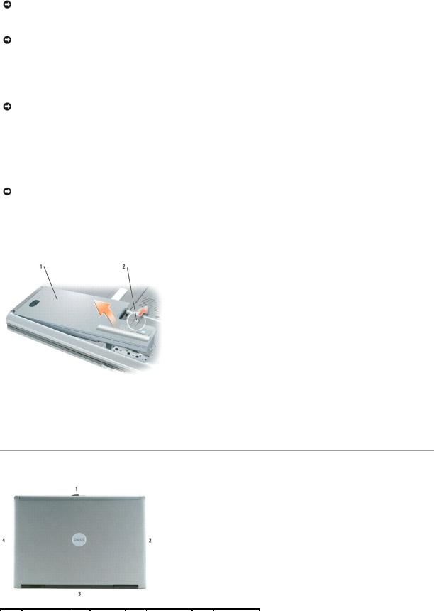
a.Slide the battery-bay release latch on the bottom of the computer toward the back of the computer until the latch is engaged.
b.Grasp the battery by the battery tab and slide the battery horizontally toward the side of the computer.
c.Lift to remove the battery from the bay.
1 |
battery |
2 |
battery-bay release latch |
|
|
|
|
|
|
|
|
7.Press the power button to ground the system board.
8.Remove any installed ExpressCards, PC Cards, or smart cards from the computer Using Cards.
Computer Orientation
1 |
front |
2 |
left |
3 |
back |
4 |
right |
|
|
|
|
|
|
|
|
|
|
Back to Contents Page |
|
|
|
|
|
|
|
|
Back to Contents Page
Internal Card with Bluetooth® Wireless Technology
Dell™ Latitude™ D830 Service Manual
CAUTION: Before performing the following procedures, follow the safety instructions in the Product Information Guide.
NOTICE: To avoid electrostatic discharge, ground yourself by using a wrist grounding strap or by periodically touching a connector on the back panel of the computer.
If you ordered an internal card with Bluetooth wireless technology with your computer, it is already installed.
1.Follow the procedures in Before You Begin.
2.Remove the hinge cover (see Hinge Cover).
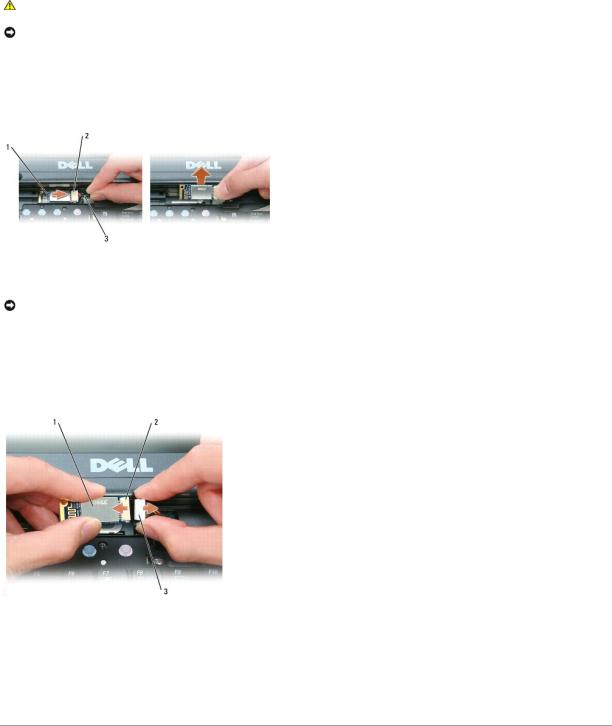
1 |
metal tab |
2 |
card |
3 |
card cable connector |
|
|
|
|
|
|
NOTICE: Be careful when removing the card to avoid damaging the card, card cable, or surrounding components.
3.Remove the card from its compartment in the computer.
a.Slide the card to the right.
b.Lift the card out of the computer.
4.Disconnect the card from the card cable connector.
1 |
card |
2 |
card connector |
3 |
card cable connector |
|
|
|
|
|
|
5.Connect the new card to the card cable connector.
6.Install the card by rotating and sliding it into the retention tab in the compartment.
7.Replace the hinge cover (see Hinge Cover).
Back to Contents Page

Back to Contents Page
Using Cards
Dell™ Latitude™ D830 Service Manual
Card Types
Card Blanks
Extended Cards
Installing a PC Card or ExpressCard
Removing a Card or Blank
Card Types
CAUTION: Before you begin any of the procedures in this section, follow the safety instructions in the Product Information Guide.
NOTE: A PC Card is not a bootable device.
The PC Card slot has one connector that supports a single Type I or Type II card. The PC Card slot supports CardBus technology and extended PC Cards. "Type" of card refers to its thickness, not its functionality.
The ExpressCard slot has one connector that supports 54-mm cards. The slot also supports adapters for 34-mm cards.
Card Blanks
Your computer shipped with a plastic blank installed in the card slots. Blanks protect unused slots from dust and other particles. Save the blank for use when no PC Card is installed in the slot; blanks from other computers may not fit your computer.
To remove the blank, see Removing a Card or Blank.
Extended Cards
An extended card (for example, a wireless network adapter) is longer than a standard card and extends outside the computer. Follow these precautions when using extended PC or ExpressCards:
•Protect the exposed end of an installed card. Striking the end of the card can damage the system board.
•Always remove an extended card before you pack the computer in its carrying case.
Installing a PC Card or ExpressCard
You can install a PC Card or ExpressCard in the computer while the computer is running. The computer automatically detects the card.
Cards are generally marked with a symbol (such as a triangle or an arrow) to indicate which end to insert into the slot. The cards are keyed to prevent incorrect insertion. If card orientation is not clear, see the documentation that came with the card.
CAUTION: Before you begin any of the procedures in this section, follow the safety instructions in the Product Information Guide.
PC Card
1.Hold the card with its orientation symbol pointing into the slot and the top side of the card facing up. The latch may need to be in the "in" position before you insert the card.
2.Slide the card into the slot until the card is completely seated in its connector.
If you encounter too much resistance, do not force the card. Check the card orientation and try again.

The computer recognizes most cards and automatically loads the appropriate device driver. If the configuration program tells you to load the manufacturer's drivers, use the floppy disk or CD that came with the PC Card.
ExpressCard
1.Hold the card with its orientation symbol pointing into the slot and the top side of the card facing up. The latch may need to be in the "in" position before you insert the card.
2.Slide the card into the slot until the card is completely seated in its connector.
If you encounter too much resistance, do not force the card. Check the card orientation and try again.
The computer recognizes most cards and automatically loads the appropriate device driver. If the configuration program tells you to load the manufacturer's drivers, use the floppy disk or CD that came with the card.
If you have an adapter, such as the one shown below, you can use 34-mm ExpressCards in the PC Card slot. For information about using the PC Card slot, see PC Card.
Removing a Card or Blank
CAUTION: Before you begin any of the procedures in this section, follow the safety instructions in your Product Information Guide.
NOTICE: Click the  icon (in the taskbar) to select a card and stop it from functioning before you remove it from the computer. If you do not stop the card in the configuration utility, you could lose data. Do not attempt to eject a card by pulling its cable, if one is attached.
Press the latch and remove the card or blank. For some latches, you must press the latch twice: once to pop the latch out, and then a second time to pop the card out.
Back to Contents Page
Back to Contents Page
Coin-Cell Battery
Dell™ Latitude™ D830 Service Manual
CAUTION: Before performing the following procedures, follow the safety instructions in the Product Information Guide.
NOTICE: To avoid electrostatic discharge, ground yourself by using a wrist grounding strap or by periodically touching a connector on the back panel of the computer.
1.Follow the procedures in Before You Begin.
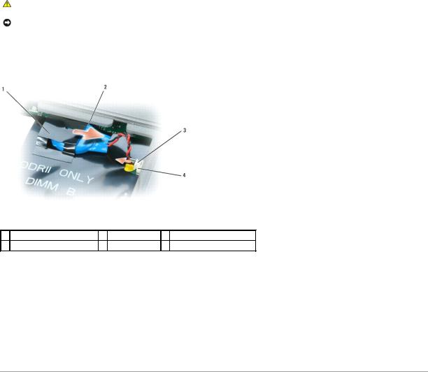
2.Remove the memory module cover (see Memory).
1 plastic sleeve |
2 coin-cell battery |
3 coin-cell battery connector |
4connector on system board
3.Remove the coin-cell battery connector from the connector on the system board.
4.Slide the battery out of the plastic sleeve.
5.Install the new coin-cell battery into the plastic sleeve.
6.Connect the cable connector to the system board.
7.Replace the keyboard.
8.Replace the hinge cover (see Hinge Cover).
Back to Contents Page

Back to Contents Page
Processor Module
Dell™ Latitude™ D830 Service Manual
Removing the Processor Module
Installing the Processor Module
Removing the Processor Module
CAUTION: Before performing the following procedures, follow the safety instructions in the Product Information Guide.
NOTICE: To avoid electrostatic discharge, ground yourself by using a wrist grounding strap or by periodically touching a connector on the back panel of the computer.
NOTICE: Press and hold the processor down by applying slight pressure to the center of the processor while turning the cam screw to prevent intermittent contact between the cam screw and processor.
NOTICE: To avoid damage to the processor, hold the screwdriver so that it is perpendicular to the processor when turning the cam screw.
1.Follow the procedures in Before You Begin.
2.Remove the hinge cover (see Hinge Cover).
3.Remove the keyboard (see Keyboard).
4.Remove the display assembly (see Display Assembly).
5.Remove the palm rest (see Palm Rest).
6.Remove the processor thermal-cooling assembly (see Processor Thermal-Cooling Assembly).
NOTICE: When removing the processor module, pull the module straight up. Be careful not to bend the pins on the processor module.
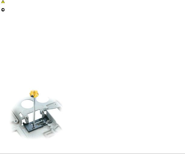
7.To loosen the ZIF socket, use a small, flat-blade screwdriver and rotate the ZIF-socket cam screw counterclockwise until it comes to the cam stop.
The ZIF-socket cam screw secures the processor to the system board. Take note of the arrow on the ZIF-socket cam screw.
1 |
ZIF-socket |
2 |
ZIF-socket cam screw |
3 |
pin-1 corner of processor |
|
|
|
|
|
|
8. Use a processor extraction tool to remove the processor module.

Installing the Processor Module
NOTICE: Ensure that the cam lock is in the fully open position before seating the processor module. Seating the processor module properly in the ZIF socket does not require force.
NOTICE: A processor module that is not properly seated can result in an intermittent connection or permanent damage to the processor and ZIF socket.
1.Align the pin-1 corner of the processor module so that it points to the triangle on the ZIF socket, and insert the processor module into the ZIF socket.
When the processor module is correctly seated, all four corners are aligned at the same height. If one or more corners of the module are higher than the others, the module is not seated correctly.
NOTICE: Hold the processor down while turning the cam screw to prevent intermittent contact between the cam screw and processor.
2. Tighten the ZIF socket by turning the cam screw clockwise to secure the processor module to the system board.
NOTE: If a new microprocessor is installed, you will receive one of the following: a new thermal-cooling assembly which will include an affixed thermal pad, or a new thermal pad along with a tech sheet to illustrate proper installation.
3.Replace the processor thermal-cooling assembly (see Processor Thermal-Cooling Assembly).
4.Update the BIOS using a flash BIOS-update program CD (see Flashing the BIOS From a CD).
Back to Contents Page
 Loading...