


549-CH
Delfield 549-CH, 561-CD, 573-CH, 573-CR, 573-CRR User Manual
...
April 2010
500 Series
Service and Installation Manual
Please read this manual completely before attempting to install or operate this equipment! Notify carrier of damage! Inspect all
components immediately. See page 2.
IMPORTANT INFORMATION
READ BEFORE USE
PLEASE SAVE THESE INSTRUCTIONS!

500 Series Display Cases Service and Installation Manual
For customer service, call (800) 733-8829, (800) 773-8821, Fax (989) 773-3210, www.delfield.com
2
©2010 The Delfield Company. All rights reserved. Reproduction without
written permission is prohibited. “Delfield” is a registered trademark of The
Delfield Company.
RECEIVING & INSPECTING EQUIPMENT ..............................2
SPECIFICATIONS ..................................................................3
PRESSURE CONTROL SETTINGS .........................................5
INSTALLATION ................................................................. 5, 6
OPERATION ..................................................................... 5, 6
CARE & CLEANING ..............................................................6
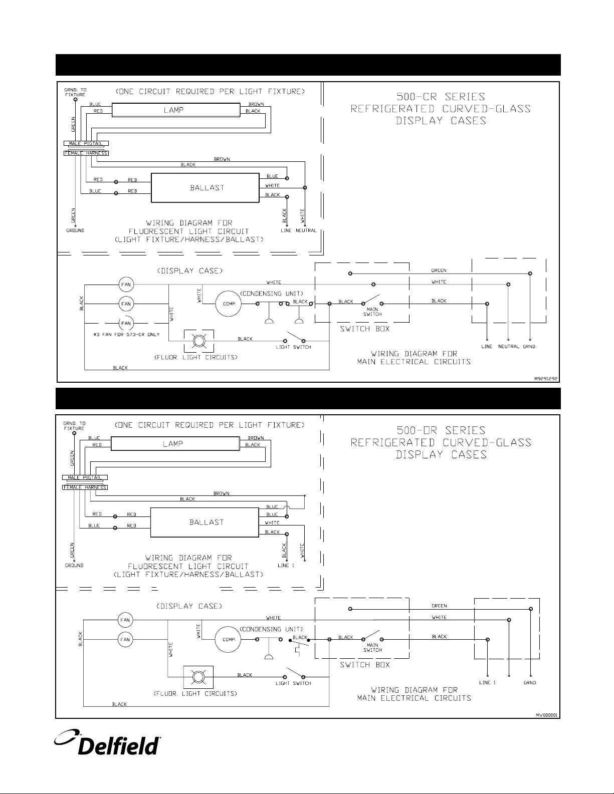
WIRING DIAGRAMS
500-CR self-contained refrigerated units .......................
7
500-OR open refrigerated units .....................................
7
500-CD dry storage units ..............................................
8
500-CH curved heated units ..........................................
8
EXPLODED VIEWS & PARTS LISTS
537-CD ..........................................................................
9
549-CD ..........................................................................
9
561-CD ........................................................................
10
573-CD ........................................................................
10
537-CR, CRR ...............................................................
11
549-CR, CRR ...............................................................
11
561-CR, CRR ...............................................................
12
573-CR, CRR ...............................................................
12
549-CH ........................................................................
13
561-CH ........................................................................
13
573-CH ........................................................................14
549-OR ........................................................................
14
FLUORESCENT LIGHT ASSEMBLY .....................................15
DOOR ASSEMBLY ...............................................................16
REFRIGERATION ASSEMBLES............................................17
FOOD WELL ASSEMBLY .....................................................18
REPLACEMENT PARTS LIST ..............................................19
STANDARD LABOR GUIDELINES ........................................20
STANDARD WARRANTIES ............................................ 21-22
NOTES ................................................................................23
The Serial number on all 500 Series units is located on the
rear of the unit, near the ON/OFF switch.
Always have the serial number of your unit available when
calling for parts or service. A complete list of authorized
Delfield parts depots can be found at www.delfield.com.
CONTENTS SERIAL NUMBER LOCATION
RECEIVING AND INSPECTING THE EQUIPMENT
Even though most equipment is shipped crated, care should
be taken during unloading so the equipment is not damaged
while being moved into the building.
1. Visually inspect the exterior of the package and skid or
container. Any damage should be noted and reported
to the delivering carrier immediately.
2. If damaged, open and inspect the contents with the
carrier.
3. In the event that the exterior is not damaged, yet upon
opening, there is concealed damage to the equipment
notify the carrier. Notification should be made verbally
as well as in written form.
4. Request an inspection by the shipping company of the
damaged equipment. This should be done within 10
days from receipt of the equipment.
5. Check the lower portion of the unit to be sure adjustable
feet are not bent.
6. Also open the compressor compartment housing and
visually inspect the refrigeration package. Be sure lines
are secure and base is still intact.
7. Freight carriers can supply the necessary damage forms
upon request.
8. Retain all crating material until an inspection has been
made or waived.
Uncrating the Equipment
First cut and remove the banding from around the crate.
Remove the front of the crate material, use of some tools will
be required. If the unit is on legs remove the top of the crate
as well and lift the unit off the skid.

500 Series Display Cases Service and Installation Manual
3
For customer service, call (800) 733-8829, (800) 773-8821, Fax (989) 773-3210, www.delfield.com
500 SERIES SPECIFICATIONS
MODEL DELFIELD VOLTS/HERTZ AMPS
NUMBER PART # PHASE (includes lights & fan)
Dry Storage Display Cases
537-CD 078-5371 115/60/1 5.0
549-CD 078-5491 115/60/1 5.0
561-CD 078-5611 115/60/1 5.0
573-CD 078-5731 115/60/1 5.0
MODEL DELFIELD NUMBER OF VOLTS/HERTZ
NUMBER PART # 12 X 20 WELLS PHASE AMPS
Heated Display Cases
549-CH 078-5494 3 120, 208-240V/60/1 19.0/21.0
561-CH 078-5614 4 120, 208-240V/60/1 24.0/27.0
573-CH 078-5734 5 120, 208-240V/60/1 30.0/34.0
MODEL DELFIELD VOLTS/HERTZ EVAPORATOR CAPACITY CABINET LOAD
NUMBER PART # H.P.* PHASE AMPS BTU/°TD BTU/HOUR
Remote Refrigerated Display Cases
537-CRR CONSULT FACTORY 1/2* 115/60/1 5.0 180 1730
549-CRR 078-5493 1/2* 115/60/1 5.0 190 2250
561-CRR 078-5613 3/4* 115/60/1 6.0 190 2770
573-CRR 078-5733 3/4* 115/60/1 6.0 290 3290
*Recommended horsepower
MODEL DELFIELD VOLTS/HERTZ CABINET LOAD SYSTEM CAPACITY REFRIGERATION
NUMBER PART # H.P. PHASE AMPS BTU/HOUR BTU/HOUR CHARGE 404A
Self-Contained Refrigerated Display Cases
537-CR 078-5372 1/2 115/60/1 12.0 1730 3258 32 oz.
549-CR 078-5492 1/2 115/60/1 12.0 2250 3316 32 oz.
561-CR 078-5612 3/4 115/60/1 16.0 2770 4919 48 oz.
573-CR 078-5732 3/4 115/60/1 16.0 3290 5387 48 oz.
MODEL DELFIELD VOLTS/HERTZ CABINET LOAD SYSTEM CAPACITY REFRIGERATION
NUMBER PART# H.P. PHASE AMPS BTU/HOUR BTU/HOUR CHARGE 404A
Open Front Refrigerated Display Cases
549-OR 078-5495 1/2 115/60/1 12.0 2030 3354 32 oz.

500 Series Display Cases Service and Installation Manual
For customer service, call (800) 733-8829, (800) 773-8821, Fax (989) 773-3210, www.delfield.com
4
Location
To meet NSF standards, all units must be sealed
to the floor.
Be sure the location chosen has a floor strong enough
to support the total weight of the cabinet and contents.
Contents fully loaded in this product line can weigh as much
as 1500 lbs. Reinforce the floor as necessary to provide for
maximum loading.
For the most efficient refrigeration, be sure to provide good
air circulation inside and out. Do not pack the refrigerator so
full that air cannot circulate. Be sure that the exterior of the
unit has access to ample air. Avoid hot corners and locations
near stoves and ovens.
Leveling
To level unit, simply lower the four adjustable rubber feet
located under the unit to the floor and adjust until unit is
level. A level cabinet will perform better because the drain
will empty properly, the doors will line up with the frames
correctly and the cabinet will not be subject to undue strain.
Plumbing
Self-contained models are standard with a condensate
evaporator. If the evaporator fails, the unit’s drain must have
an outlet to an appropriate drainage area or container.
Moisture collecting from improper drainage
can create a slippery surface on the floor and
a hazard to employees. It is the owner’s and
operator’s responsibility to provide a container or
outlet for drainage.
Electrical connection
Refer to the amperage data on page 3, the serial tag, your
local code or the National Electrical Code to be sure the
unit is connected to the proper power source. A protected
circuit of the correct voltage and amperage must be run for
connection of the line cord, or permanent connection to the
unit.
Self-contained units have an ON/OFF switch located on
the operators side. Simply turn the switch to ON to begin
operation.
The power switch should be turned to OFF and the
unit disconnected from the power source whenever
performing service or maintenance functions.
CAUTION
On self-contained models, after turning the ON/OFF switch
to ON, the unit’s compressor will begin operating. Delfield
display cases are designed to maintain an operational
temperature of 36°F to 40°F.
Do not load the storage area in a way that restricts the air
flow. Overloading will result in the loss of temperature. Do
not throw items into the storage area. The interior of the
cabinet and the blower coil may be damaged by this type of
neglect, which is not covered under your warranty.
These units use HFC-404A refrigerant, and
have a lock-out high pressure limiting device.
Under severe overloading conditions, in the
event of a condenser fan failure or a plugged or
blocked condenser, this device may shut down
the refrigeration system. See page 17 for part number
information if a replacement is required.
INSTALLATION: 500 CD, CR, CRR & OR
OPERATION: 500 CD, CR, CRR & OR

500 Series Display Cases Service and Installation Manual
5
For customer service, call (800) 733-8829, (800) 773-8821, Fax (989) 773-3210, www.delfield.com
Pressure Control
The temperature is controlled by an adjustable pressure
control located in the machine compartment. An adjustable
control has the word COLDER near the knob, with an arrow
to indicate the adjustment direction. These controls are
field adjustable and do not require a service agent. If you
have any questions, feel free to contact the Delfield Service
Department.
The refrigeration systems on self-contained CR & OR models
were adjusted at the factory to maintain between 36°F and
40°F. No adjustment should be necessary. If adjustment
does become needed however, the factory recommended
settings are:
Low-pressure settings (CR models): 82 psi cut-in,
47 psi cut-out, 35 psi differential.
Low-pressure settings (OR models): 82 psi cut-in,
40 psi cut-out, 42 psi differential.
Operating pressures: High, 170 to 200 psi. Low, 30 to 37
psi.
In attempting to adjust the pressure control, you can
do damage to your unit by accidentally adjusting the
differential. Please make small incremental adjustments
if a temperature adjustment is necessary, please contact
the service department at Delfield (800) 733-8829 #1,
or your local service agent. Delfield is not responsible
for charges incurred while having the pressure control
adjusted.
CONTROL SETTINGS: 500 CR & OR

500 Series Display Cases Service and Installation Manual
For customer service, call (800) 733-8829, (800) 773-8821, Fax (989) 773-3210, www.delfield.com
6
Installation should be done by personnel
certified and licensed to install and maintain
electrical appliances.
Location
Be sure the location chosen has a floor strong enough
to support the total weight of the cabinet and contents.
Contents fully loaded into this product line can weigh as
much as 1500 lbs. Reinforce the floor as necessary to
provide for maximum loading.
Leveling
A level cabinet looks better and will perform better because
the drain pan will drain properly, the doors will line up with
the frames properly, and the cabinet will not be subject to
undue strain.
Electrical connection
Connections must be made in accordance with
all applicable local codes and/or the National
Electrical Code. Refer to the wiring diagrams on
pages 6 and 7.
INSTALLATION: 500 CH
OPERATION: 500 CH
For most efficient operation, keep covered insets empty in
each well during preheating and when the well is not in use.
Dry operation
1) Pre-heat the well on “HIGH” for approximately
15 minutes.
2) After pre-heating, set the control to your
desired serving temperature.
Only 6” (15.2cm) deep insets should be used with a dry
food well. When operated dry, the bottom of the food well
will discolor. Refer to cleaning instructions to remove
discoloration.
Temperature
Product in pans . . . . . . . . . . . . . . . . . . . . . . 140°F to 160°F
S
T PE
S
NOTE: Intended for DRY OPERATION ONLY.
CLEANING: ALL MODELS
Clean the food wells daily. Wash with non-abrasive cleanser
and non-abrasive pad. If necessary, a mild abrasive may be
used. Do not use steel wool.
For all stainless steel parts, use mild, non-abrasive soap
or detergent and warm water. This may be followed by an
application of stainless steel cleaner or polish which will
eliminate water spotting and fingerprints and will bring out
the finish of the stainless steel.
Do not use a hose or pressure wash on these
units. The water will damage the electrical
components.
Cleaning the condenser (refrigerated units)
In order to maintain proper refrigeration, the condenser
fins must be cleaned of dust, dirt and grease every three
months. If condenser is totally blocked after three months
increase cleaning frequency. Clean the condenser with a
vacuum cleaner or stiff brush. If extremely dirty, use a
commercially available condenser cleaner.
Cleaning the sliding door assembly
All Delfield 500 Series display cases feature a Pike sliding
door assembly. Regular cleaning of door tracks with mild
soap and water will keep them free of foreign matter
insuring many years of use. The glass may be cleaned with
a glass cleaner.
Before the unit is used the first time for serving, turn the
temperature knob to “10” and heat the well for 20 minutes.
Do not be alarmed if smoke appears; this preheat should
burn off any residue or dust on the heating element.
Hot surfaces can cause serious burns. Always
wear some type of protective covering on your
hands and arms when removing lids or pans
from the unit.
Never place food directly into the well. Always use pans.
Always place covers on pans when not serving to prevent
food from drying out and to reduce your operating cost.
500 Series Display Cases Service and Installation Manual
7
For customer service, call (800) 733-8829, (800) 773-8821, Fax (989) 773-3210, www.delfield.com
WIRING: 500 CR
WIRING: 500 OR
NEUTRAL
NEUTRAL

500 Series Display Cases Service and Installation Manual
For customer service, call (800) 733-8829, (800) 773-8821, Fax (989) 773-3210, www.delfield.com
8
WIRING: 500 CD
WIRING: 500 CH
WHT
WHT
WHT
WHT
WHT
WHT
WHT
WHT
WHT
WHT
WHT
WHT
WHT
WHT
J
P P P P
RED
RED
RED
RED
RED
RED
RED
HEATED SHELF
120V
P LL
2
1
H
H
1 2
208V208V208V
21
P L L
2
H
H
1
21
LLP
2
H
H
1
2
LL
1
P
H
2
1
H
BLK
BLK
BLK
BLK
BLK
BLK
BLK
BLK
BLK
BLK
BLK
BLK
BLK
 Loading...