


18600 Series and CTP-NB
Service and Installation Manual
Please read this manual completely before attempting to install or operate this equipment! Notify carrier of damage! Inspect all components immediately.
18600PTL |
18600PTBM |
18600BUCM |
|
Pizza Tables with LiquiTec® Rail |
Pizza Tables with Raised Rail |
Work Tables |
|
|
|
|
|
|
|
|
|
18600PDL |
18600BSTM |
CTP-NB |
Dual LiquiTec® Rail Prep Table |
Work Table with Backsplash |
Countertop Condiment Rail |
CAUTION
Important Information
Read Before Use
Please Save These Instructions!
February 2013
18600 and CTP-NB Series Service and Installation Manual
Important Warning And Safety Information
WARNING |
Read This Manual Thoroughly Before Operating, Installing, Or Performing Maintenance On The Equipment. |
WARNING |
Failure To Follow Instructions In This Manual Can Cause Property Damage, Injury Or Death. |
WARNING |
Do Not Store Or Use Gasoline Or Other Flammable Vapors Or Liquids In The Vicinity Of This Or Any Other |
|
Appliance. |
WARNING |
Unless All Cover And Access Panels Are In Place And Properly Secured, Do Not Operate This Equipment. |
WARNING |
This Appliance Is Not Intended For Use By Persons Who Lack Experience Or Knowledge, Unless They Have |
|
Been Given Supervision Or Instruction Concerning Use Of The Appliance By A Person Responsible For Their |
|
Safety. |
WARNING |
This Appliance Is Not To Be Played With. |
Warning |
Do Not Clean With Water Jet. |
WARNING |
Do Not Use Electrical Appliances Inside The Food Storage Compartment Of This Appliance. |
CAUTION |
Observe the following: |
|
|
• |
Minimum clearances must be maintained from all walls and combustible materials. |
|
• |
Keep the equipment area free and clear of combustible material. |
|
• |
Allow adequate clearance for air openings. |
|
• |
Operate equipment only on the type of electricity indicated on the specification plate. |
|
• |
Unplug the unit before making any repairs. |
|
• |
Retain this manual for future reference. |
2 |
For customer service, call (800) 733-8829, (800) 773-8821, Fax (989) 773-3210, www.delfield.com |

18600 and CTP-NB Series Service and Installation Manual
Contents |
|
Receiving & Inspecting Equipment............................................ |
3 |
Serial Number Information......................................................... |
4 |
Warranty Information................................................................. |
4 |
Regulatory Certifications............................................................ |
4 |
Specifications.............................................................................. |
5 |
Refrigerant Charges.................................................................... |
6 |
Installation ................................................................................. |
6 |
Operation |
|
18600PTBM & PTL Series...................................................... |
7 |
18600BUCM & BSTM Series.................................................. |
7 |
18600PDL Series..................................................................... |
8 |
CTP-NB Series......................................................................... |
8 |
Pressure Control Settings.......................................................... |
9 |
Temperature Control Settings..................................................... |
9 |
Care And Cleaning............................................................... |
10-11 |
Wiring Diagram |
|
18600PTBM & PTL Series.................................................... |
12 |
18600BUCM & BSTM Series................................................ |
13 |
18600PDL.............................................................................. |
13 |
CTP-NB Series....................................................................... |
14 |
Replacement Parts............................................................... |
15-24 |
Standard Labor Guidelines....................................................... |
25 |
Notes.................................................................................... |
26-27 |
Receiving And Inspecting The Equipment
Even though most equipment is shipped crated, care should be taken during unloading so the equipment is not damaged while being moved into the building.
1.Visually inspect the exterior of the package and skid or container. Any damage should be noted and reported to the delivering carrier immediately.
2.If damaged, open and inspect the contents with the carrier.
3.In the event that the exterior is not damaged, yet upon opening, there is concealed damage to the equipment notify the carrier. Notification should be made verbally as well as in written form.
4.Request an inspection by the shipping company of the damaged equipment. This should be done within 10 days from receipt of the equipment.
5.Check the lower portion of the unit to be sure legs or casters are not bent.
6.Also open the compressor compartment housing and visually inspect the refrigeration package. Be sure lines are secure and base is still intact.
7.Freight carriers can supply the necessary damage forms upon request.
8.Retain all crating material until an inspection has been made or waived.
Uncrating the Equipment
First cut and remove the banding from around the crate. Remove the front of the crate material, use of some tools will be required. If the unit is on legs remove the top of the crate and lift the unit off the skid. If the unit is on casters it can be "rolled" off the skid.
For customer service, call (800) 733-8829, (800) 773-8821, Fax (989) 773-3210, www.delfield.com |
3 |
18600 and CTP-NB Series Service and Installation Manual
Serial Number Information
The serial number on 18600 Series units is located on the electrical specifications tag affixed inside the compressor section next to the pressure control.
The serial number on CTP-NB Series units is located on the front of the unit.
Always have the serial number of your unit available when calling for parts or service.
Warranty may be deemed invalid if other than authorized OEM (original equipment manufacture) replacement parts are used in Delfield equipment.
©2013 The Delfield Company. All rights reserved. Reproduction without written permission is prohibited. “Delfield” is a registered trademark of The Delfield Company.
Warranty Information
Visit http://www.delfield.com/minisite/service/warranty_info to:
•Register your product for warranty.
•Verify warranty information.
•View and download a copy of your warranty.
Regulatory Certifications
Models are certified by:
 National Sanitation Foundation (NSF)
Underwriters Laboratories (UL)
Underwriters Laboratories of Canada (ULC)
4 |
For customer service, call (800) 733-8829, (800) 773-8821, Fax (989) 773-3210, www.delfield.com |

18600 and CTP-NB Series Service and Installation Manual
Specifications
18600PTBM Pizza tables with raised rail
|
1/3 Pan Size |
|
# Of |
Shelf Max |
Shelf Area |
Volume |
BTU Load |
BTU Sys. Cap. |
|
Voltz/Hertz/ |
|
NEMA |
Ship Weight |
Model |
Capacity |
# Of Doors |
Shelves |
Load (LBS) |
FT2 |
FT3 |
Base/Rail |
Base/Rail |
H.P. |
Phase |
Amps |
Plug |
LBS/KG |
18648PTBM |
6 |
(1) 27” |
1 |
124 |
3.95 |
10.23 |
470/441 |
2001/952 |
1/4 |
115/60/1 |
10.0 |
5-15P |
520/236 |
|
|
|
|
|
|
|
|
|
|
|
|
|
|
18660PTBM |
7 |
19” & 27” |
2 |
70/124 |
6.51 |
15.12 |
694/617 |
2409/1208 |
1/3 |
115/60/1 |
12.0 |
5-15P |
575/260 |
|
|
|
|
|
|
|
|
|
|
|
|
|
|
18672PTBM |
9 |
(2) 27” |
2 |
124 |
7.9 |
18.10 |
776/794 |
2967/1587 |
1/2 |
115/60/1 |
14.0 |
5-20P |
635/288 |
|
|
|
|
|
|
|
|
|
|
|
|
|
|
18691PTBM |
11 |
(2)27” & (1) 19” |
3 |
124/70 |
10.29 |
24.48 |
1062/1058 |
3537/1865 |
1/2 |
115/60/1 |
14.0 |
5-20P |
770/350 |
|
|
|
|
|
|
|
|
|
|
|
|
|
|
18699PTBM |
12 |
(3) 27” |
3 |
124 |
11.85 |
27.46 |
1144/1147 |
3537/1945 |
1/2 |
115/60/1 |
14.0 |
5-20P |
805/365 |
|
|
|
|
|
|
|
|
|
|
|
|
|
|
186114PTBM |
14 |
(3) 32” |
3 |
140 |
14.46 |
33.05 |
1297/1323 |
5169/2433 |
3/4 |
115/60/1 |
16.0 |
5-20P |
927/420 |
|
|
|
|
|
|
|
|
|
|
|
|
|
|
18600BUCM Work tables
|
|
# Of |
Shelf Max |
Shelf Area |
Volume |
BTU Load |
BTU Sys. Cap. |
|
Voltz/Hertz/ |
|
NEMA |
Ship Weight |
Model |
# Of Doors |
Shelves |
Load (LBS) |
FT2 |
FT3 |
Base/Rail |
Base/Rail |
H.P. |
Phase |
Amps |
Plug |
LBS/KG |
18648BUCM |
(1) 27” |
1 |
124 |
3.95 |
10.23 |
475/NA |
1462/NA |
1/5 |
115/60/1 |
8.0 |
5-15P |
390/177 |
|
|
|
|
|
|
|
|
|
|
|
|
|
18660BUCM |
19” & 27” |
2 |
70/124 |
6.51 |
15.12 |
686/NA |
1462/NA |
1/5 |
115/60/1 |
8.0 |
5-15P |
435/197 |
|
|
|
|
|
|
|
|
|
|
|
|
|
18672BUCM |
(2) 27” |
2 |
124 |
7.90 |
18.10 |
856/NA |
2263/NA |
1/4 |
115/60/1 |
10.0 |
5-15P |
495/225 |
|
|
|
|
|
|
|
|
|
|
|
|
|
18691BUCM |
(2)27” & (1) 19” |
3 |
124/70 |
10.29 |
24.48 |
1169/NA |
2263/NA |
1/4 |
115/60/1 |
10.0 |
5-15P |
535/243 |
|
|
|
|
|
|
|
|
|
|
|
|
|
18699BUCM |
(3) 27” |
3 |
124 |
11.85 |
27.46 |
1220/NA |
2263/NA |
1/4 |
115/60/1 |
10.0 |
5-15P |
594/269 |
|
|
|
|
|
|
|
|
|
|
|
|
|
186114BUCM |
(3) 32” |
3 |
106 |
14.46 |
37.24 |
1373/NA |
2813/NA |
1/3 |
115/60/1 |
12.0 |
5-15P |
685/310 |
|
|
|
|
|
|
|
|
|
|
|
|
|
18600BSTM Work table with backsplash
|
|
# Of |
Shelf Max |
Shelf Area |
Volume |
BTU Load |
BTU Sys. Cap. |
|
Voltz/Hertz/ |
|
NEMA |
Ship Weight |
Model |
# Of Doors |
Shelves |
Load (LBS) |
FT2 |
FT3 |
Base/Rail |
Base/Rail |
H.P. |
Phase |
Amps |
Plug |
LBS/KG |
18648BSTM |
(1) 27” |
1 |
124 |
3.95 |
10.23 |
475/NA |
1462/NA |
1/5 |
115/60/1 |
8.0 |
5-15P |
390/177 |
|
|
|
|
|
|
|
|
|
|
|
|
|
18660BSTM |
19” & 27” |
2 |
70/124 |
6.51 |
15.12 |
686/NA |
1462/NA |
1/5 |
115/60/1 |
8.0 |
5-15P |
435/197 |
|
|
|
|
|
|
|
|
|
|
|
|
|
18672BSTM |
(2) 27” |
2 |
124 |
7.90 |
18.10 |
856/NA |
2261/NA |
1/4 |
115/60/1 |
10.0 |
5-15P |
495/225 |
|
|
|
|
|
|
|
|
|
|
|
|
|
18691BSTM |
(2)27” & (1) 19” |
3 |
124/70 |
10.29 |
24.48 |
1169/NA |
2261/NA |
1/4 |
115/60/1 |
10.0 |
5-15P |
535/243 |
|
|
|
|
|
|
|
|
|
|
|
|
|
18699BSTM |
(3) 27” |
3 |
124 |
11.85 |
27.46 |
1220/NA |
2591/NA |
1/3 |
115/60/1 |
12.0 |
5-15P |
594/269 |
|
|
|
|
|
|
|
|
|
|
|
|
|
186114BSTM |
(3) 32” |
3 |
106 |
14.46 |
37.24 |
1373/NA |
2591/NA |
1/3 |
115/60/1 |
12.0 |
5-15P |
685/310 |
|
|
|
|
|
|
|
|
|
|
|
|
|
18600PTL Pizza table with LiquiTec® rail
|
1/3 Pan Size |
|
# Of |
Shelf Max |
Shelf Area |
Volume |
BTU Load |
BTU Sys. Cap. |
|
Voltz/Hertz/ |
|
NEMA |
Ship Weight |
Model |
Capacity |
# Of Doors |
Shelves |
Load (LBS) |
FT2 |
FT3 |
Base/Rail |
Base/Rail |
H.P. |
Phase |
Amps |
Plug |
LBS/KG |
18648PTL |
6 |
(1) 27” |
1 |
124 |
3.95 |
10.23 |
470/441 |
2001/952 |
1/4 |
115/60/1 |
10.0 |
5-15P |
520/236 |
|
|
|
|
|
|
|
|
|
|
|
|
|
|
18672PTL |
9 |
(2) 27” |
2 |
124 |
7.90 |
18.10 |
776/794 |
2967/1587 |
1/2 |
115/60/1 |
14.0 |
5-20P |
635/288 |
|
|
|
|
|
|
|
|
|
|
|
|
|
|
18699PTL |
12 |
(3) 27” |
3 |
124 |
11.85 |
27.46 |
1144/1147 |
3537/1945 |
1/2 |
115/60/1 |
14.0 |
5-20P |
805/365 |
|
|
|
|
|
|
|
|
|
|
|
|
|
|
18600PDL Pizza table with Dual LiquiTec® rails
|
1/3 Pan Size |
|
# Of |
Shelf Max |
Shelf Area |
Volume |
BTU Load |
BTU Sys. Cap. |
|
Voltz/Hertz/ |
|
NEMA |
Ship Weight |
Model |
Capacity |
# Of Doors |
Shelves |
Load (LBS) |
FT2 |
FT3 |
Base/Rail |
Base/Rail |
H.P. |
Phase |
Amps |
Plug |
LBS/KG |
18648PDL |
6 |
(1) 27” |
1 |
124 |
3.95 |
10.23 |
424/1058 |
2001/1865 |
1/5, |
115/60/1 |
10.1 |
5-20P |
691/313 |
|
|
|
|
|
|
|
|
|
1/3 |
|
|
|
|
|
|
|
|
|
|
|
|
|
|
|
|
|
|
18672PDL |
9 |
(2) 27” |
2 |
124 |
7.90 |
18.10 |
703/1588 |
2001/3174 |
1/5, |
115/60/1 |
12.7 |
5-20P |
873/396 |
|
|
|
|
|
|
|
|
|
1/2 |
|
|
|
|
|
|
|
|
|
|
|
|
|
|
|
|
|
|
CTP-NB Counter top containment rail
|
1/3 Pan Size |
|
|
|
BTU System |
|
Voltz/Hertz/ |
|
NEMA |
Ship Weight |
Model |
Capacity |
|
# Of Adapter Bars |
BTU Load |
Capacity |
H.P. |
Phase |
Amps |
Plug |
LBS/KG |
|
|
|
|
|
|
|
|
|
|
|
CTP8146-NB |
4 |
5 |
|
305 |
523 |
1/5 |
115/60/1 |
4.0 |
5-15P |
121/54.9 |
|
|
|
|
|
|
|
|
|
|
|
CTP8160-NB |
6 |
7 |
|
462 |
653 |
1/5 |
115/60/1 |
4.0 |
5-15P |
158/71.7 |
|
|
|
|
|
|
|
|
|
|
|
For customer service, call (800) 733-8829, (800) 773-8821, Fax (989) 773-3210, www.delfield.com |
5 |

18600 and CTP-NB Series Service and Installation Manual
Refrigerant Charges
Refrigerant Charges For 18600 Series Units: |
|
|
|
|
|
||
18648-PTBM & PTL . . . . |
. |
16 oz. (454g) |
18660-BUCM & BSTM . |
. |
. |
. |
16 oz. (454g) |
18660-PTBM . . . . . . . |
|
.24 oz. (680g) |
18672-BUCM & BSTM . |
. |
. |
. |
16 oz. (454g) |
18672-PTBM & PTL . . . . |
. |
32 oz. (907g) |
18691-BUCM & BSTM . |
. |
. |
. |
16 oz. (454g) |
18691-PTBM . . . . . . . |
|
.32 oz. (907g) |
18699-BUCM & BSTM . |
. |
. |
. |
24 oz. (680g) |
18699-PTBM & PTL . . . . |
. |
32 oz. (907g) |
186114-BUCM & BSTM . |
. |
. |
|
.24 oz. (680g) |
186114-PTBM . . . . . . |
.48 oz. (1361g) |
18648PDL . . . . . . |
. |
. |
|
40 oz. (1134g) |
|
18648-BUCM & BSTM . . . |
. |
16 oz. (454g) |
18672PDL . . . . . . |
. |
. |
|
56 oz. (1588g) |
Refrigerant Charges For CTP-NB Series Units: |
||||||||
CTP8146-NB . |
. |
. |
. |
. |
. |
. |
. |
8 oz. (227g) |
CTP8160-NB . |
. |
. |
. |
. |
. |
. |
. |
8 oz. (227g) |
CTP8175-NB . |
. |
. |
. |
. |
. |
. |
.16 oz. (454g) |
|
Installation
Location
These units are intended for indoor use only. Be sure the location chosen has a floor strong enough to support the total weight of the cabinet and contents. A fully loaded 72” long model may weigh as much as 1200 pounds. Reinforce the floor as necessary to provide for maximum loading.
For the most efficient refrigeration, be sure to provide good air circulation inside and out.
Inside cabinet: Do not pack refrigerator so full that air cannot circulate.
Outside cabinet: Be sure that the unit has access to ample air. Avoid hot corners and locations near stoves and ovens.
It is recommended that the unit be installed no closer than 1” from any wall. PDL models also require 14” (36cm) clearance at the top and 6” (15cm) clearance at the bottom (casters).
Leveling
A level cabinet looks better and will perform better because the drain pan will drain properly, the doors will line up with the frames properly, and the cabinet will not be subject to undue strain.
Some models have casters for your convenience, for ease of cleaning underneath and for mobility. It is important that the unit be installed in a stable condition with the front casters locked before operating.
Plumbing
Self-contained models are standard with a condensate evaporator. If, for some reason, a unit does not have a condensate evaporator, or the evaporator fails, the unit’s drain must have an outlet to an appropriate drainage area or container.
Moisture collecting from improper drainage can create a slippery surface on the floor and a hazard to employees. It is the owner’s responsibility to provide
CAUTION a container or outlet for drainage.
Electrical connection
Refer to the amperage data, the serial tag, your local code or the National Electrical Code to be sure the unit is connected to the proper power source. A protected circuit of the correct voltage and amperage must be run for connection of the line cord, or permanent connection to the unit.
The power switch must be turned to OFF and the unit disconnected from the power source whenever performing service or maintenance functions.
Never operate the unit without the louvered panel in place!
6 |
For customer service, call (800) 733-8829, (800) 773-8821, Fax (989) 773-3210, www.delfield.com |
18600 and CTP-NB Series Service and Installation Manual
Operation: 18600PTBM & PTL Series
Product should be loaded into the unit with care. Failure to heed these recommendations could result in damage to the interior of the cabinet or the blower coil.
This unit is equipped with two on/off switches located behind the louvered machine compartment panel. The unit’s compressor and all evaporator fans will begin operating when the main power switch is turned to the ON position. Temperature ranges for the base are 36°F to 40°F.
The switch labeled rail is for the raised rail. The rail switch is accessible through a 1.5” diameter hole in the louvered panel. Turning this switch to the ON position will activate the refrigeration for the rail. Temperature ranges for the raised rail are 33°F to 41°F.
Product located in the rail must be removed at the end of day. This allows you to turn the rail off at night to save energy and the rail will have time to defrost as needed.
A minimum of one hour of off time per day with the pans removed from the rail is required to properly defrost the rail.
The power must be turned to OFF and the unit disconnected from the power source whenever performing service or maintenance functions.
Never operate the unit without the louvered panel in place!
All R404A models have a high pressure limiting device. Under severe overloading conditions, or in the event of a condenser fan failure or a plugged or blocked condenser, this device may shut down the refrigeration system. This device will automatically reset, but determining the cause of the high pressure condition should be investigated by a qualified refrigeration technician.
Refrigerator Evaporator Fan Operation
When the refrigerator is initially powered up or immediately following a power outage the unit will begin cooling after a 3-6 minute delay. During normal operation the evaporator fan pulses independently of the compressor as dictated by the controller as follows:
1.During the cooling mode, compressor and evaporator fan run simultaneously.
2.During the compressor off mode, evaporator fan pulses three minutes on and three minutes off.
3.During an actual defrost event other than the off-cycle defrost, compressor stays off but the evaporator fan runs continuously.
|
Cooling Cycle |
|
Defrost Cycle |
||
|
|
|
|
|
|
Compressor On |
Compressor Off |
Compressor Off |
|||
|
|
|
|
|
|
Evap Fan |
Evap Fan |
Evap Fan |
Evap Fan |
Evap Fan |
Evap Fan |
On |
Off |
On |
Off |
On |
Off |
X |
|
Cycles On 3-Min, Off |
X |
|
|
|
3-Min |
|
|||
|
|
|
|
||
Operation: 18600BUCM & BSTM Series
After turning the ON/OFF switch to ON, the units compressor will begin operating. Delfield refrigerated bases are designed to maintain an operational temperature of 36°F to 40°F.
Product should be loaded into the unit with care. Failure to heed these recommendations could result in damage to the interior of the cabinet or the blower coil.
Overloading the storage area, restricting the air flow and continuous opening and closing of the doors and drawers will hamper the units ability to maintain operational temperature.
Refrigerator Evaporator Fan Operation
When the refrigerator is initially powered up or immediately following a power outage the unit will begin cooling after a 3-6 minute delay. During normal operation the evaporator fan pulses independently of the compressor as dictated by the controller as follows:
1.During the cooling mode, compressor and evaporator fan run simultaneously.
2.During the compressor off mode, evaporator fan pulses three minutes on and three minutes off.
3.During an actual defrost event other than the off-cycle defrost, compressor stays off but the evaporator fan runs continuously.
|
Cooling Cycle |
|
Defrost Cycle |
||
|
|
|
|
|
|
Compressor On |
Compressor Off |
Compressor Off |
|||
Evap Fan |
Evap Fan |
Evap Fan |
Evap Fan |
Evap Fan |
Evap Fan |
On |
Off |
On |
Off |
On |
Off |
|
|
|
|
|
|
X |
|
Cycles On 3-Min, Off |
X |
|
|
|
3-Min |
|
|||
|
|
|
|
||
|
|
|
|
|
|
For customer service, call (800) 733-8829, (800) 773-8821, Fax (989) 773-3210, www.delfield.com |
7 |
18600 and CTP-NB Series Service and Installation Manual
Operation: 18600PDL Series
Product should be loaded into the unit with care. Failure to heed these recommendations could result in damage to the interior of the cabinet or the blower coil.
This unit is equipped with two on/off switches located behind the louvered machine compartment panel. The unit’s compressor and all evaporator fans will begin operating when the main power switch is turned to the ON position. Temperature ranges for the base are 36°F to 40°F (2°C to 4°C).
The switch labeled rail is for the raised rails. The rail switch is accessible through a 1.5” (3.8cm) diameter hole in the louvered panel. Turning this switch to the ON position will activate the refrigeration for the rails. Temperature ranges for the raised rails are 33°F to 41°F (0.5°C to 5°C).
Product located in the rails must be removed at the end of day. This allows you to turn the rails off at night to save energy and the rails will have time to defrost as needed.
A minimum of one hour of off time per day with the pans removed from the rails is required to properly defrost the rails.
The power must be turned to OFF and the unit disconnected from the power source whenever performing service or maintenance functions.
Never operate the unit without the louvered panel in place!
All R404A models have a high pressure limiting device. Under severe overloading conditions, or in the event of a condenser fan failure or a plugged or blocked condenser, this device may shut down the refrigeration system. This device will automatically reset, but determining the cause of the high pressure condition should be investigated by a qualified refrigeration technician.
Refrigerator Evaporator Fan Operation
When the refrigerator is initially powered up or immediately following a power outage the unit will begin cooling after a 3-6 minute delay. During normal operation the evaporator fan pulses independently of the compressor as dictated by the controller as follows:
1.During the cooling mode, compressor and evaporator fan run simultaneously.
2.During the compressor off mode, evaporator fan pulses three minutes on and three minutes off.
3.During an actual defrost event other than the off-cycle defrost, compressor stays off but the evaporator fan runs continuously.
|
Cooling Cycle |
|
Defrost Cycle |
||
|
|
|
|
|
|
Compressor On |
Compressor Off |
Compressor Off |
|||
|
|
|
|
|
|
Evap Fan |
Evap Fan |
Evap Fan |
Evap Fan |
Evap Fan |
Evap Fan |
On |
Off |
On |
Off |
On |
Off |
|
|
|
|
|
|
X |
|
Cycles On 3-Min, Off |
X |
|
|
|
3-Min |
|
|||
|
|
|
|
||
Operation: ctp-nb Series
The unit is equipped with one on/off switch located on the right end of the unit. The unit’s compressor will begin operating when this switch is turned to the ON position. Temperature ranges for the rail are 33°F to 41°F.
Product located in the rail must be removed at the end of day. This allows you to turn the rail OFF at night to save energy and the rail will have time to defrost as needed.
A minimum of one hour of off time per day with the pans removed from the rail is required to properly defrost the rail.
The power switch must be turned to OFF and the unit disconnected from the power source whenever performing service or maintenance functions. Never operate the unit without the louvered panel in place!
8 |
For customer service, call (800) 733-8829, (800) 773-8821, Fax (989) 773-3210, www.delfield.com |
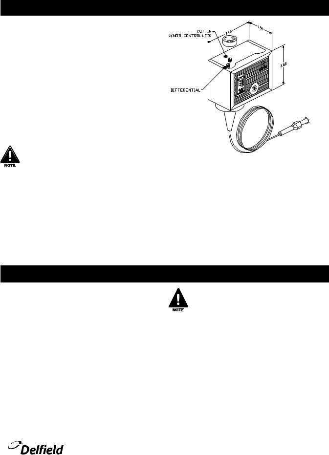
Pressure Control Settings
The factory recommended low-pressure control settings for 18600PTBM’s are: 55psi cut-in and 30psi cut-out to maintain proper temperature for product in the rail. The interior temperature is controlled by the thermostat mounted in the mechanical compartment.
The factory recommended low-pressure control settings for 18600PTL’s are: 20psi (1.38bar) cut-in and 10psi (0.70bar) cut-out. The base and rail temperatures are controlled by the thermostats mounted in the machine compartment.
A pressure control is located in the machine compartment. An adjustable control has the word COLDER on the knob, with an arrow to indicate the adjustment direction. These controls are field adjustable and do not require a service agent.
In attempting to adjust the pressure control, you can do damage to your unit by accidentally adjusting the differential. Please make small incremental adjustments if a temperature adjustment is necessary. It may take an hour or longer to realize the temperature change depending on the application and location of the
unit.
Please contact the service department at Delfield (800) 733-8829 or your local service agent. Delfield is not responsible for charges incurred while having the pressure control adjusted.
Temperature Control Settings
A thermostat controls temperature in the 18600PTBM base,
18600PTL base, 18600PTL rail, BUCM, BSTM, 18600PDL base and 18600PDL rail.
Thermostats are located in the machine compartment. They are field adjustable and do not require a service agent. The factory setting is 2.5. Set toward 1 for higher temperatures and toward 7 for lower temperatures.
18600 and CTP-NB Series Service and Installation Manual
Please make small incremental adjustments if a temperature adjustment is necessary. It may take an hour or longer to realize the temperature change depending on the application and location of the unit.
Contact the service department at Delfield +1 (989) 773-7981 or your local service agent for additional assistance. Delfield is not responsible for charges incurred while adjusting the thermostat.
For customer service, call (800) 733-8829, (800) 773-8821, Fax (989) 773-3210, www.delfield.com |
9 |
 Loading...