


Contents
CONTENTS
1. |
Specifications ................................................................................................ |
2 |
|
2. |
Outline and Dimensions ................................................................................. |
3 |
|
3. |
Operation ..................................................................................................... |
5 |
|
4. |
Wiring Diagram.......................................................................................... |
17 |
|
5. |
Refrigerant Cycle ......................................................................................... |
22 |
|
6. |
Control Block Diagram................................................................................. |
23 |
|
7. |
Electric Circuit Diagram................................................................................ |
24 |
|
8. |
Trouble Shooting.......................................................................................... |
27 |
|
9. |
Disassembly Instructions ............................................................................... |
43 |
|
|
1) |
Indoor Unit.............................................................................................. |
43 |
|
2) |
Outdoor Unit........................................................................................... |
45 |
|
3) |
Exploded Diagram (Indoor Unit) ............................................................... |
47 |
|
4) |
Exploded Diagram (Outdoor Unit) ............................................................ |
50 |
|
5) |
Control Box Assembly.............................................................................. |
56 |
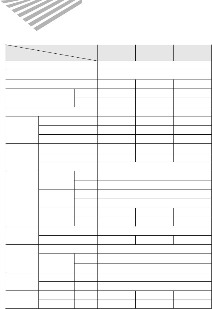
1. SPECIFICATIONS
DSA-151L/DSA-181L/DSB-181L |
|
|
|
||
|
MODEL |
|
DSA-151L |
DSA-181L |
DSB-181L |
ITEM |
|
|
|||
|
|
|
|
|
|
Function |
|
|
|
Cooling |
|
Class |
|
|
|
T |
|
Power Supply |
|
|
AC 208~230V, 60Hz |
AC 208~230V, 60Hz |
AC 220~240V, 50Hz |
Capacity |
|
W |
4,300 |
5,100 |
5,100 |
|
|
Btu/h |
15,500 |
17,500 |
17,500 |
Dehumidification |
|
|
1.98l/h |
2.3l/h |
2.3l/h |
|
Running Current |
|
6.6A |
8.3A |
9.8A |
Electrical |
Power Input |
|
1,450W |
1,785W |
1,950W |
Data |
|
||||
|
|
|
|
|
|
|
Starting Current |
|
42A |
44A |
46A |
|
Type |
|
Rotary |
Rotary |
RECIPRO |
Compressor |
Model |
|
RCA150A001 |
ECB185211A |
CRDQ-0200-PFJ |
|
Capacitor |
|
|
30µF/400 VAC |
|
|
Type |
Indoor |
|
Cross Flow Fan |
|
|
|
Outdoor |
|
Propeller Fan |
|
Fan |
Capacitor |
Indoor |
|
1.2µF/400 VAC |
|
|
|
|
|
|
|
|
|
Outdoor |
|
3µF/400 VAC |
|
|
Motor Model |
Indoor |
IC-9425DWKH6A |
IC-9425DWKH6A |
IC-9425DWKC5A |
|
|
Outdoor |
AM12DPD05 |
AM12DPD05 |
AM12DPD04 |
Refrigerant |
Control |
|
|
Capillary |
|
|
|
|
|
|
|
(R-22) |
Charge Q'ty |
|
1,250g |
1,450g |
1,150g |
|
|
||||
|
Type |
|
|
Flare |
|
Connection |
OD |
Indoor |
|
1/4”(6.35mm) |
|
|
(Liquid/Suction) |
Outdoor |
|
1/2”(12.7mm) |
|
Dimensions |
Indoor |
|
|
1,035 x 322 x 205 |
|
|
Outdoor |
|
|
800 x 615 x 277 |
|
Net Weight |
Indoor |
|
11.7Kg |
11.7Kg |
11.7Kg |
|
Outdoor |
|
43Kg |
44Kg |
55.8Kg |
|
|
|
2 |
|
|

OUTLINE AND DIMENSIONS |
INDOOR UNIT |
2. |
1 |
DSA-151L/DSA-181L/DSB-181L
Connecting¿‹ Æ˘˜ ˙`Pipe
Plate”fi Mounting`⁄˘˙
453 |
|
1035 |
`⁄„«REMOCON…–‚fi‚ ˜ |
|
3
‰˙‡»Grille– Insert‚Ø– ‚–
 Body‰˙‡»– ‚ ˆ…
322
205
Filter-L |
Filter-R |

2 OUTDOOR UNIT
DSA-151L/DSA-181L/DSB-181L
Inlet |
Inlet |
|
|
277 |
|
367 |
|
Panel Top |
Outlet |
Cabinet |
Handle |
4
Discharge |
615 |
Grille |
|
800
Foot |
Service Valve |
3. OPERATION
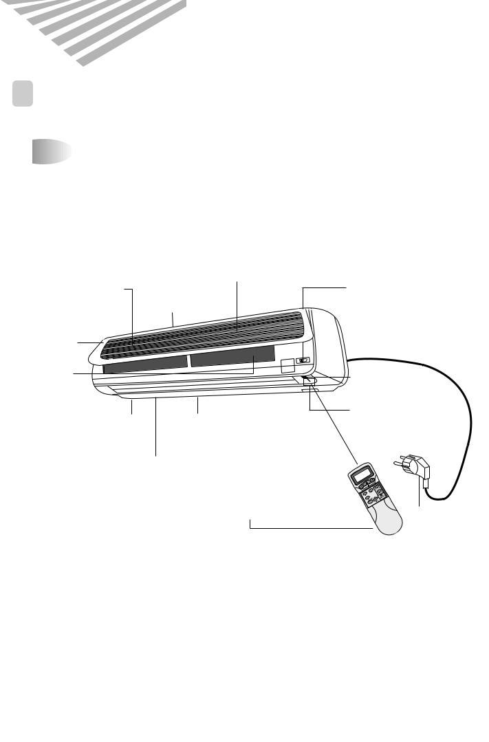
1PARTS OF NAME AND FUNCTION
DSA-151L/DSA-181L/DSB-181L


 Indoor Unit
|
Deodorizing Filter |
|
|
|
Removes bad |
|
|
|
smells from the air. |
|
|
Electrostatic Filter |
|
Test/Emergency/ |
|
Removes dust |
Air In |
Remote Switch |
|
particles |
Slide to select |
||
|
|
the desired position. |
|
Indoor Cover |
|
|
|
Air Cleaning |
|
Remote Sensor |
|
Filters |
|
|
|
Removes dust |
|
|
|
and prohibits |
|
Indicators |
|
germs. |
|
||
Fan Direction |
Indicate the |
||
Cold Air |
|||
|
(Up/Down) |
AC setting. |
|
|
|
||
Fan Direction |
|
||
(Left/Right) |
|
||
|
LCD Remote Controller |
Power Plug |
|
5

DSA-151L/DSA-181L/DSB-181L
Indoor Unit Display |
Switch Panel |
■ Remote Control Signal Receiver
This place is the part to receive the signal if it receive the signal, you can hear the signal “beep. beep”.
EMERGENCY REMOTE
|
Timer |
|
Quick |
|
Airclean |
|
ON |
Timer (Yellow) |
ON (Red) |
Lights during the time |
Lights when the |
reservation mode. |
operation is going on. |
Quick (Red) |
Air clean (Green) |
Lights during the |
|
time Quick |
|
Mode. |
|
■There is a switch panel at inside of Front Panel. At the time of operating, open the Front Panel.
Emergency switch can be used when the remote controller is lost or Testing.
Remote switch is usually used by remote controller.
6

DSA-151L/DSA-181L/DSB-181L


 Outdoor Unit
AC Cover
Remove cover to access the AC
AIR IN connection from this unit to the indoor unit.
 Connection Wire
 Drain Hose
 COPPER TUBING
AIR OUT
 Service Valves
The indoor and outdoor units are connected by copper tubes which are connected here.
Grounding Screw
Ground the unit here.
Ground Wire (Not supplied)
7

2REMOTE CONTROLLER
DSA-151L/DSA-181L/DSB-181L


 Name of Each Button
AUTO
FAN SPEED Button |
|
|
|
Press to select the fan speed |
|
|
|
(High " ", Middle " ", |
MODE |
FAN SPEED |
FAN DIR. |
Low " "). |
|||
MODE Button |
|
|
|
Press to cycle through the modes |
SLEEP |
|
FAN DIR. |
(Auto/Quick/Cooling/Fan/Dry) |
TIMER |
|
|
|
|
|
|
SLEEP Button |
ON/OFF |
ENTER/ |
TURBO/MILD |
Press to set the unit for |
|
CANCEL |
|
|
|
|
|
the sleep mode. |
|
|
|
TIMER ON/OFF Button
Press to set the unit of or on time. (0.5, 1, 1.5, 2, 2.5, 3, 4, 5, 6, 8, 10, 12, 16, 20, 24hr)
TIMER ENTER/CANCEL Button
Press to enter a timer setting or to cancel timer setting
Display
Displays information pertaining to unit.
ON/OFF Button
Press to turn the unit on or off.
TEMPERATURE Buttons
Press to raise or lower the desired temperature.
 FAN DIR.
  Button
Press to select up/down direction for fan.
 FAN DIR.
 Button
Press to select left/right direction for fan.
TURBO/MILD
Press to be colder the unit.
COVER
Slide down to access most of the remote buttons. Slide down further to access the battery compartment.
8

3REMOTE CONTROLLER DISPLAY
DSA-151L/DSA-181L/DSB-181L
MODE Indicators (Auto/Quick/Cool/Fan/Dehumidifier)
Lights to indicate the mode selected.
AUTO
FAN Indicators
Lights to indicate the fan speed.
NATURAL Indicator 


Lights to indicate the speeds simulating a breeze.
FAN DIRECTION Indicators
Lights to indicate the fan direction.
TIMER Indicators (Include sleep)
Lights to indicate the timer function mode.
TEMPERATURE & RESERVATION TIME lndicators
Lights to indicate the temperature or time.


 Replacing Batteries
1 |
Open the cover after |
2 |
Put the drycell by + – |
3 |
Close the cover after |
|
pressing the arrow |
direction. |
|
pushing into arrow |
|||
direction and pulling out. |
|
|
direction. |
|||
|
|
|
+ |
– |
|
|
|
|
|
– |
+ |
|
|
9
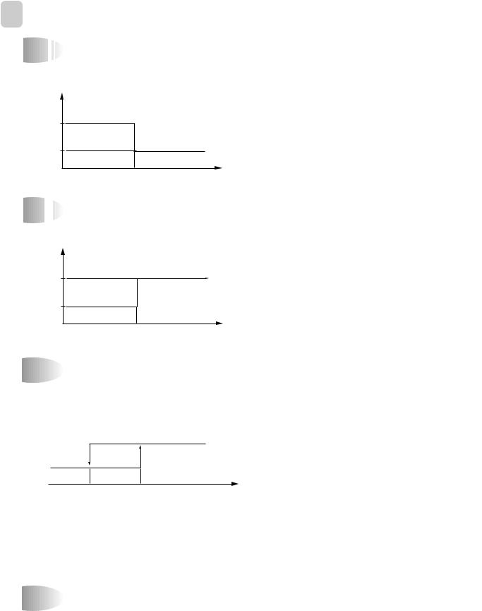
4 DESCRIPTION OF FUNCTIONS


 OFF
OFF
 -
-
 Timer
Timer
If you set time in OFF-Timer Mode, the unit will stop at the set time.
Unit ON
ON
Unit OFF
OFF
SET Time |
HOUR |


 ON
ON
 -
-
 Timer
Timer
If you set time in ON-Timer Mode, the unit will run at the set time.
Unit ON |
|
ON |
|
Unit OFF |
|
OFF |
|
SET Time |
HOUR |


 Control of Room Temperature
(1)Range of setting temperature: 18~32°C
(2)Setting temperature: Operating temperature of compressor
COMP (ON)
COMP (OFF)
-1˚C |
0˚C |
Temperature |
|
|
(RT-DT) |
|
(COOLING) |
|
Room temperatrue (< setting temperature
Compressor OFF
Room temperature (> setting temperafure
Compressor ON
(3) During the time of test operating, Fan (Indoor, Outdoor) and Compressor is running regardless of room temperature.


 Buzzer
If the Indoor Unit Display receive the signal of Remote Controller, you can hear the signal "beep –" or "beep, beep".
10


 Fan
Fan


 Speed (Indoor Unit)
(1)Motor speed (high speed, normal speed, low speed).
(2)Remote controller setting fan speed. (Auto, L, M, H, Natural)
(3)Relation of operating mode between fan speed.
|
FAN ONLY |
COOL |
DEHUMI- |
AUTO |
Quick |
|
DIFICATION |
||||
|
|
|
|
|
|
H |
H |
H |
X |
H |
H |
M |
M |
M |
X |
M |
X |
L |
L |
L |
X |
L |
X |
Auto |
X |
Auto |
Auto |
Auto |
X |
Natural |
Natural |
Natural |
X |
Natural |
X |
|
|
|
|
|
|
(4) Automatic Operation
If the unit is set in 'AUTO' mode, the unit operates automatically according to the room temperature to keep the room temperature comfortable.
(COOLING)
• DSA-151L/DSA-181L/DSB-181L
H
M
L 
|
|
|
|
|
0 +1°C +2°C |
(RT-DT) |
|||
11


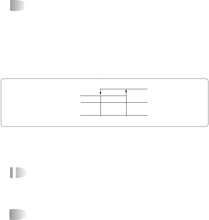
 Sleep
Sleep

 Mode
Mode
(1)When you are going to sleep, select sleep switch and the unit controls the room to the desired temperature. (The unit will not operate after 4 hour)
(2)For changing the temperature.
Difference
desired temperature between room temperature (°C)
|
|
|
0.5°C |
|
|
0.5°C |
|
Desired |
0.5°C |
|
|
|
|
|
|
Temperature |
|
|
|
0 |
0.5 |
1.0 |
HOUR |
SET TIME
(3) To cancel sleep mode, press the SLEEP button again or press the MODE button once.: the SLEEP indicator will disappear in the display.


 Emergency Operation
(1)When the remote controller is lost, damaged or the battery is discharged, the Emergency operation can be used to run the unit.
(2)The setting conditions of Emergency operation are as follows.
•Operation mode: AUTO
•Preset temperature: 26°C
•Fan speed: AUTO
12


 Frost
Frost

 Prevention of Indoor Unit
When the unit operates at low ambient temperature, frost may appear on the Evaporator. When the indoor coil temperature is lower than 0°C at the end of 10 minutes of continuous compressor operation from the start, the microcomputer of the unit stops the compressor to protect the unit from the frost. The control procedure for indoor coil freeze protection.
1)The compressor and outdoor fan turn off.
2)Indoor fan operates according to user set speed.
3)The normal operation returns when the indoor coil temperature is higher than 7°C or equal to 7°C.
ON
Compressor and
OFF
Outdoor Fan
Set Speed
Indoor Fan
0°C 7°C
(Indoor coil temperature)


 3
3


 min. Time Delay of Compressor
In normal operation, there is a time delay of three minutes between turn off and turning back on including initial power up.


 Indoor Fan Motor Starting
When indoor fan motor is on, it always starts at normal speed and then it operates desired speed.
13


 Auto
Auto

 Mode
Mode
(1) When the room temperature is higher than 28°C (Cooling Mode) !Compressor and lndoor Fan
|
|
|
|
ON |
|
|
OFF |
|
|
|
|
° |
(Room temperature- |
|
|
|||||
|
|
|
||||
|
|
|
|
|
||
|
|
|
|
|
||
|
|
|
|
|
||
-1 |
0 |
C |
Desired temperature) |
|||
|
||||||
@ The fan will automatically operate as following Figure
|
|
|
|
|
|
H |
|
|
||
|
|
|
M |
|
|
|
|
|
|
|
|
|
|
|
|
|
|
|
|||
|
|
|
|
|
|
|
|
|
||
L |
|
|
|
|
|
|
|
|
°C |
(Room temerature- |
|
|
|
|
|
|
|||||
|
|
|
|
|
|
|
||||
|
|
|
|
|
|
|
|
|
||
|
|
|
|
|
|
|
|
|
Desired temperature) |
|
0 |
+1 |
+2 |
|
|||||||
|
|
|||||||||
|
|
|
||||||||
(2)When the room temperature is lower than 28°C and higher than 22°C (Dehumidification Mode).
(3)When the room temperature is lower than 22°C (Fan only).
14


 Dehumidification Mode
!Desired temperature < Room temperature Outdoor Fan, Compressor : ON
Indoor Fan : Low speed
@Desired temperature >Room temperature Compressor : 3 min/ON, 5 min/OFF
Indoor Fan : 3 min 30 second/ON, 4 min 30 second/OFF Fan Speed : Low speed
#Room temperature >18°C Compressor : OFF
Indoor Fan : 1 min/ON, 7 min/OFF Fan speed : Low speed


 Air
Air


 Discharge Direction
(1)When you turn on the unit, the flaps move to the position of keeping the room temperature comfortable.
(2)The air discharge direction is below.
Up/Down  On/Off
Left/Right  On/Off


 Quick Mode (Powerful Cooling)
(1) Cooling condition !Fan Speed: High speed
@ Air discharge direction: Fixed
# Set temperature: 18°C (Fixed) $ Operation Mode: Cooling Mode % Compressor and Outdoor Fan
ON
OFF
 (Room temperature-18˚C) -1 0
15


 Self
Self
 -
-
 Diagnostic Function
The control will contain diagnostic test to verify the integrity of the system.
(1)Error Code Display Pattern
!ON LAMP: ON (Red) LED ON/OFF
@ Error Code (Display in Emergency Mode only)
ERROR CODE |
|
|
|
|
|
DISPLAY PATTEN |
ERROR CONTENTS |
||||||||
|
|
|
|
|
|
|
|
|
|
|
|
|
|
|
|
|
|
|
|
|
|
|
|
|
|
|
8 seconds |
|
|||
|
|
|
|
|
|
|
|
|
|
|
|
|
|
|
Room air thermistor, connector |
1 |
|
|
|
|
|
|
|
|
0.5 second |
|
|
||||
|
|
|
|
|
|
|
|||||||||
|
|
|
|
|
|
|
|
|
|
|
|
|
|
Indoor coil thermistor, connector |
|
|
|
|
|
|
|
|
|
|
|
|
|
|
|
|
|
|
|
|
|
|
|
|
|
|
|
|
|
|
|
|
|
|
|
|
|
|
|
|
|
|
|
|
|
|
|
|
|
|
|
|
|
|
|
|
|
|
|
|
8 seconds |
Compressor, Electrical parts of |
|||
|
|
|
|
|
|
|
|
|
|
|
|
|
|
|
|
2 |
|
|
|
|
|
|
|
|
0.5 second |
|
comp. Gas leak |
||||
|
|
|
|
|
|
|
|
|
|
|
|
|
|
||
|
|
|
|
|
|
|
|
|
|
|
|
|
|
|
|
|
|
|
|
|
|
|
|
|
|
|
|
|
|
|
|
|
|
|
|
|
|
|
|
|
|
|
|
|
|
|
|
16
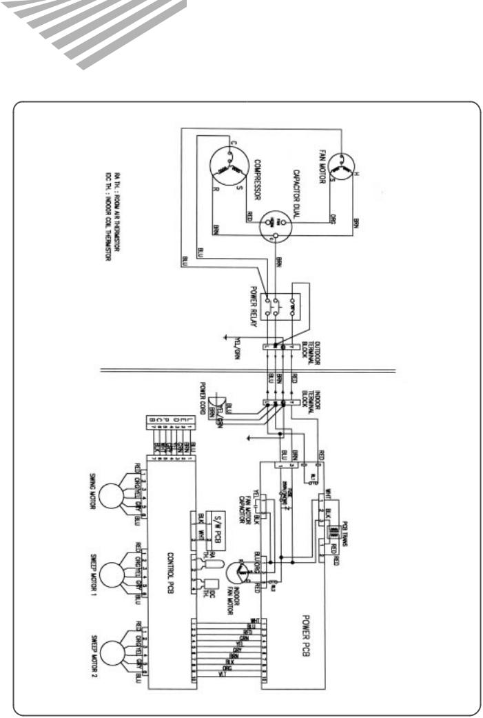
4. WIRING DIAGRAM
DSA-151L
UNIT INDOOR UNIT OUTDOOR
17

DSA-181L/DSB-181L
18
 Loading...