


MFC9500
Brother MFC9500, MFC9000, MFC7650MC, MFC7550MC, MFC6550MC Service Manual
...
FACSIMILE EQUIPMENT
SERVICE MANUAL
MODEL: FAX3550/3650/8000P/8200P
MFC4450/4550/4550plus
MFC6550MC/7550MC/7650MC
MFC9000/9500

© Copyright Brother 1998
All rights reserved.
No part of this publication may be reproduced in any
form or by any means without permission in writing
from the publisher.
Specifications are subject to change without notice.

PREFACE
This publication is a Service Manual covering the specifications, construction, theory of operation, and maintenance of the Brother facsimile equipment. It includes information required for
field troubleshooting and repair—disassembly, reassembly, and adjustment—so that service
personnel will be able to understand equipment function, to rapidly repair the equipment and
order any necessary spare parts.
To perform appropriate maintenance so that the facsimile equipment is always in best condition
for the customer, the service personnel must adequately understand and apply this manual.
This manual is made up of six chapters and appendices.
CHAPTER I. GENERAL DESCRIPTION
CHAPTER II. INSTALLATION
CHAPTER III. THEORY OF OPERATION
CHAPTER IV. DISASSEMBL Y/REASSEMBLY AND LUBRICATION
CHAPTER V. MAINTENANCE MODE
CHAPTER VI. ERROR INDICATION AND TROUBLESHOOTING
APPENDICES Circuit Diagrams
This manual describes the model and its versions to be destined for major countries. The specifications
and functions are subject to change depending upon each destination.

SAFETY INFORMATION
Laser Safety (110 - 120V Model only)
This printer is certified as a Class 1 laser product under the US Department of Health and Human
Services (DHHS) Radiation Performance Standard according to the Radiation Control for Health
and Safety Act of 1968. This means that the printer does not produce hazardous laser radiation.
Since radiation emitted inside the printer is completely confined within the protective housings and
external covers, the laser beam cannot escape from the machine during any phase of user operation.
CDRH Regulations (110 - 120V Model only)
The Center for Device and Radiological Health (CDRH) of the US Food and Drug Administration
implemented regulations for laser products on August 2, 1976. These regulations apply to laser
products manufactured from August 1, 1976. Compliance is mandatory for products marketed in the
United States. The label shown below indicates compliance with the CDRH regulations and must be
attached to laser products marketed in the United States.
The label for Japanese products
MANUFACTURED: AUGUST 1998 K
BROTHER INDUSTRIES, LTD.
15-1 Naeshiro-cho Mizuho-ku Nagoya 467-8561, Japan.
This product complies with FDA radiation
performance standards, 21 CFR Subchapter J.

CHAPTER I.
GENERAL DESCRIPTION

CONTENTS
1. EQUIPMENT OUTLINE................................................................................. I-1
1.1External Appearance and Weight........................................................... I-1
1.2Components............................................................................................I-1
2. SPECIFICATIONS..........................................................................................I-2

1. EQUIPMENT OUTLINE
1.1 External Appearance and Weight
The figure below shows the equipment appearance and approximate dimensions.
251 (H)
Weight: Machine proper Approx. 8.5 kg (excluding the drum unit and toner cartridge)
In package Approx. 13.5 kg (FAX3550/3650/8000P/8200P)
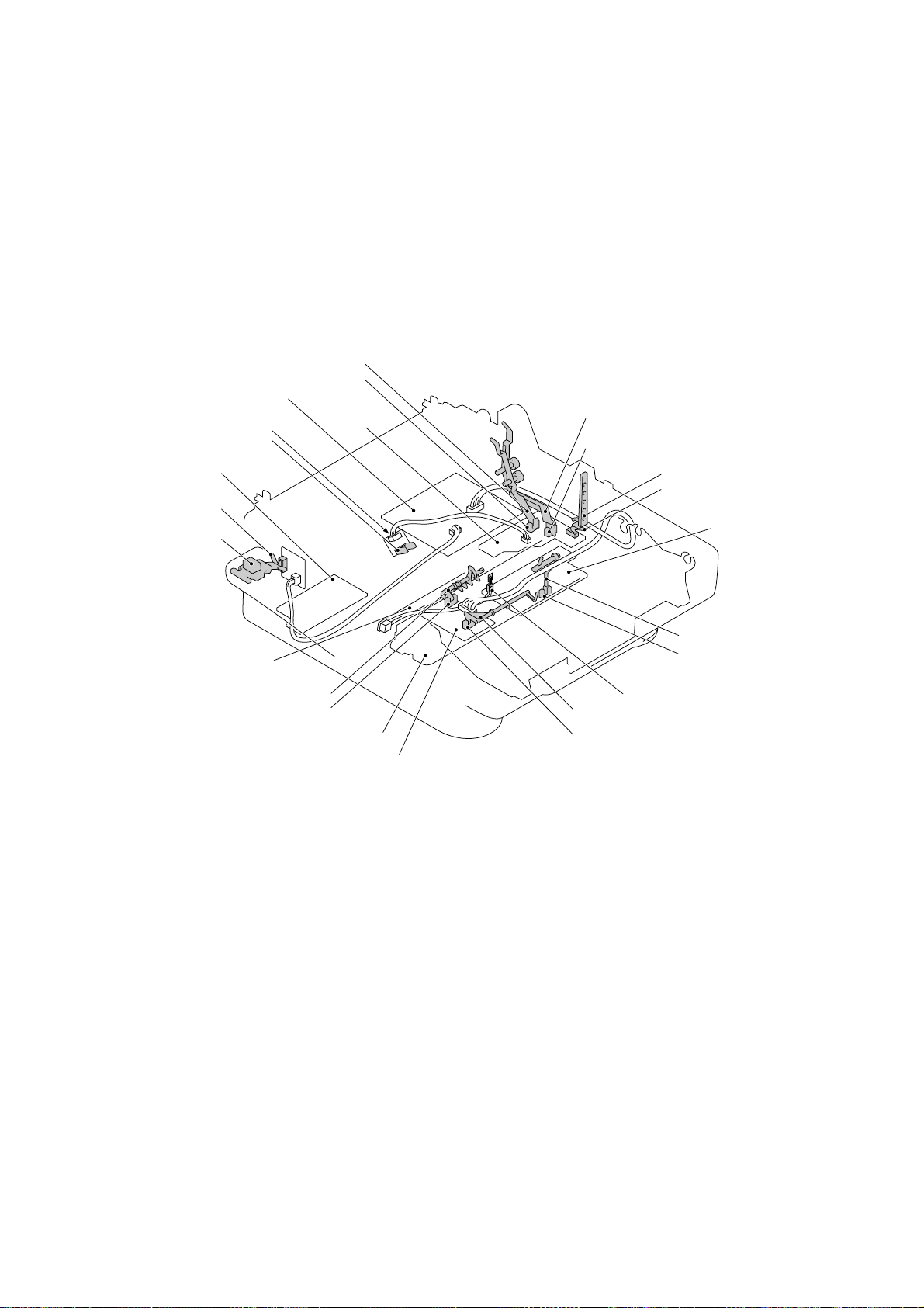
1.2 Components
The equipment consists of the following major components:
Multi-purpose
sheet feeder
Drum unit with toner
cartridge loaded
Laser unit
383 (W)
(excluding the handset)
Approx. 14 kg (MFC4450/4550/4550plus/6550MC/7550MC/
452 (D)
(Unit: mm)
7650MC/9000/9500)
Top cover
Control panel ASSY
Heat-fixing unit
Inner cover
Handset
Gear drive unit
Low-voltage power
supply ASSY
Bottom plate
Main cover
Scanner frame ASSY
NCU PCB ASSY
Main PCB
Relay PCB
High-voltage power
supply ASSY
I – 1

2. SPECIFICATIONS
MODEL FAX3550 MFC4550 MFC6550MC MFC7550MC
COLOR 1267 1138 1138 1138
PRINTER Option
Engine — HL-720 HL-730 HL-730
PPM — 6 6 6
dpi — 600 x 600 600 x 600 600 x 600
Paper Capacity 200 200 200 200
Standards — Windows GDI (600x600) Windows GDI (600x600) Windows GDI (600x600)
Emulation — No PCL4 (300x300) PCL4 (300x300)
Memory (Typical) — 512 KB 512 KB 1 MB
Memory (Min.) — 300 KB 400 KB 1 MB
Fonts Resident — No 24-bit map (PCL4 Comp) 24-bit map (PCL4 Comp)
Fonts Disk Based — No Yes Yes
Paper Handling LTR, LGL, A4 LTR, LGL, EXE, A4, B5, A5 LTR, LGL, EXE, A4, B5, A5 LTR, LGL, EXE, A4, B5, A5
Multi-purpose Sheet Custom Size (2.85x5-8x14) Custom Size (2.85x5-8x14) Custom Size (2.85x5-8x14) Custom Size (2.85x5-8x14)
Feeder
Printer Driver — Windows 3.1, 95 Driver with Windows 3.1, 95 Driver with Windows 3.1, 95 Driver with
Toner Life (5%/page) 2200 pages 2200 pages 2200 pages 2200 pages
Utility Software — — RPC RPC
SCANNER Option
Color/Mono — Mono Mono Mono
Gray Scale — 64 256 256
dpi — 400 x 400 600 x 600 600 x 600
Twain — Yes Yes Yes
ADF Capacity (pages) (30) 30 30 30
Formats — TIFF/BMP (by M/L) TIFF/BMP (by M/L) TIFF/BMP (by M/L)
OCR — Option Yes Yes
Envelope (BL/C5/COM 10/Mona) Envelope (BL/C5/COM 10/Mona) Envelope (BL/C5/COM 10/Mona) Envelope (BL/C5/COM 10/Mona)
Auto Installer Program Auto Installer Program Auto Installer Program
(1/2)
COPY
dpi 200 x 400 200 x 400 600 class 600 class
No. of Copies 1-99 1-99 1-99 1-99
Sorting No No Yes Yes
Reduction/Enlargement 50-200% 50-200% 50-200% 50-200%
FAX
Modem ROCKWELL V12 ROCKWELL V12 ROCKWELL V24 ROCKWELL V24
Modem Speed 14400 bps (FAX only) 14400 bps (FAX only) 14400 bps (FAX only) 14400 bps (FAX only)
CCITT Group G3 G3 G3 G3
Coding Method MH/MR/MMR MH/MR/MMR MH/MR/MMR MH/MR/MMR
Transmission Speed 6 sec. 6 sec. 6 sec. 6 sec.
Input/Output Width 8.5"/8.5" 8.5"/8.5" 8.5"/8.5" 8.5"/8.5"
LCD Size 16 x 1 16 x 2 16 x 2 16 x 2
Super Fine Yes (Send only) Yes (Send only) Yes (Send only) Yes
Gray Scale 64 64 64 64
Smoothing Yes Yes Yes Yes
Handset Yes Yes Yes Yes
One-touch Dial 20 x 2 12 x 2 12 x 2 12 x 2
Speed Dial 100 36 36 100
Telephone Index Yes Yes Yes Yes
Contrast Super L/Auto/Super D Super L/Auto/Super D Super L/Auto/Super D Super L/Auto/Super D
Multi-resolution Transmission
FAX/TEL Switch Yes Yes Yes Yes
Distinctive Ringing Yes Yes Yes Yes
Caller ID Yes Yes Yes Yes
Next FAX-reservation Yes Yes Yes Yes
Help Yes Yes Yes Yes
TAD Interface Yes Yes Yes Yes
Yes Yes Yes Yes
I – 2

MODEL FAX3650 MFC4450 MFC4550plus MFC7650MC
COLOR 1267 1138 1138 1138
PRINTER Option
Engine — HL-720 HL-720 HL-730
PPM — 6 6 6
dpi 200 x 200 600 x 600 600 x 600 600 x 600
Paper Capacity 200 200 200 200
Standards Windows GDI (200x200) Windows GDI (600x600) Windows GDI (600x600) Windows GDI (600x600)
Emulation — No PCL4 (300x300) PCL4 (300x300)
Memory (Typical) — 512 KB 512 KB 1 MB
Memory (Min.) — 300 KB 400 KB 600 KB
Fonts Resident — No 24-bit map (PCL4 Comp) 24-bit map (PCL4 Comp)
Fonts Disk Based — No Yes Yes
Paper Handling LTR, LGL, A4 LTR, LGL, A4, B5, A5 LTR, LGL, A4, B5, A5 LTR, LGL, A4, B5, A5
Multi-purpose Sheet — Custom Size (2.85x5-8x14) Custom Size (2.85x5-8x14) Custom Size (2.85x5-8x14)
Feeder
Printer Driver — Windows 3.1, 95 Driver with Windows 3.1, 95 Driver with Windows 3.1, 95 Driver with
Toner Life (5%/page) 2200 pages 2200 pages 2200 pages 2200 pages
Utility Software — — RPC RPC
SCANNER Option
Color/Mono — Mono Mono Mono
Gray Scale — 64 64 256
dpi — 400 x 400 400 x 400 600 x 600
Twain — Yes Yes Yes
ADF Capacity (pages) — 30 30 30
Formats (Import) —
Formats (Export) — TIFF/BMP/UNI TIFF/BMP/MAX TIFF/BMP/MAX
OCR — Option Yes Yes
Envelope (BL/C5/COM 10/Mona) Envelope (BL/C5/COM 10/Mona) Envelope (BL/C5/COM 10/Mona)
Auto Installer Program Auto Installer Program Auto Installer Program
TIFF/BMP/PCX/DCX/BTF/BTX/UNI TIFF/BMP/PCX/DCX/BTF/BTX/MAX TIFF/BMP/PCX/DCX/BTF/BTX/MAX
(1/2)
COPY
dpi 200 x 400 200 x 400 200 x 400 600 class
No. of Copies 1-99 1-99 1-99 1-99
Sorting Yes No No Yes
Reduction/Enlargement 50-200% 50-200% 50-200% 50-200%
FAX
Modem ROCKWELL V12 Toshiba ROCKWELL V12 ROCKWELL V24
Modem Speed 14400 bps (FAX only) 9600 bps (FAX only) 14400 bps (FAX only) 14400 bps (FAX only)
CCITT Group G3 G3 G3 G3
Coding Method MH/MR/MMR MH/MR/MMR MH/MR/MMR MH/MR/MMR
Transmission Speed 6 sec. 9 sec. 6 sec. 6 sec.
Input/Output Width 8.5"/8.5" 8.5"/8.5" 8.5"/8.5" 8.5"/8.5"
LCD Size 16 x 1 16 x 2 16 x 2 16 x 2
Super Fine Yes Yes Yes Yes
Gray Scale 64 64 64 64
Smoothing Yes Yes Yes Yes
Handset Yes No Yes Yes
One-touch Dial 20 x 2 12 x 2 12 x 2 12 x 2
Speed Dial 100 36 36 100
Telephone Index Yes Yes Yes Yes
Contrast Super L/Auto/Super D Super L/Auto/Super D Super L/Auto/Super D Super L/Auto/Super D
Multi-resolution Transmission
FAX/TEL Switch Yes Yes (with External) Yes Yes
Distinctive Ringing Yes Yes (with External) Yes Yes
Caller ID Yes No Yes Yes
Next FAX-reservation Yes Yes Yes Yes
Help Yes Yes Yes Yes
TAD Interface Yes Yes Yes Yes
Yes Yes Yes Yes
I – 3

MODEL FAX8000P MFC9000 MFC9500 FAX8200P
COLOR 1138 1138 1138 1138
PRINTER Option Option
Engine — HL-730 HL-730 —
PPM — 6 6 —
dpi —
Paper Capacity 200 200 200 200
Standards — Windows GDI Windows GDI —
Emulation — PCL4 PCL4 —
Memory (Typical) — 512 KB 512 KB —
Memory (Min.) — 400 KB 400 KB —
Fonts Resident — 24-bit map (PCL4 Comp) 24-bit map (PCL4 Comp) —
Fonts Disk Based — Yes Yes —
Paper Handling A4, B5, A5 A4, B5, A5 A4, B5, A5 A4
Multi-purpose Tray
Printer Driver — Windows 3.1, 95 Driver with Windows 3.1, 95 Driver with
Toner Life (5%/page) 2200 pages 2200 pages 2200 pages 2200 pages
Utility Software —
SCANNER Option Option
Color/Mono — Mono Mono —
Gray Scale — 256 256 —
dpi — 600 x 600 600 x 600 —
Twain — Yes Yes —
ADF Capacity (pages) 30 30 30 —
Formats — TIFF/BMP TIFF/BMP —
OCR — Option Yes —
Custom Size (73x127-126x350 mm) Custom Size (73x127-216x350 mm) Custom Size (73x127-216x350 mm)
Envelope (DL/C5/COM 10/Mona) Envelope (DL/C5/COM 10/Mona) Envelope (DL/C5/COM 10/Mona)
600 x 600 (GDI) / 300 x 300 (PCL4) 600 x 600 (GDI) / 300 x 300 (PCL4)
Auto Installer Program Auto Installer Program
Mac Driver (Option) Mac Driver (Option)
Remote Priter Console (RPC) Remote Printer Console (RPC)
—
—
—
—
(1/2)
COPY
dpi 200 x 400 300 x 400 300 x 400 200 x 400
No. of Copies 1-99 1-99 1-99 1-99
Sorting
Reduction/Enlargement 50-200% 50-200% 50-200% 50-200%
FAX
Modem ROCKWELL V12 ROCKWELL V12 ROCKWELL V24 ROCKWELL V12
Modem Speed 14400 bps (FAX only) 14400 bps (FAX only) 14400 bps (FAX only) 14400 bps (FAX only)
CCITT Group G3 G3 G3 G3
Coding Method MH/MR/MMR MH/MR/MMR MH/MR/MMR MH/MR/MMR
Transmission Speed 6 sec. 6 sec. 6 sec. 6 sec.
Input/Output Width 8.5"/8.5" 8.5"/8.5" 8.5"/8.5" 8.5"/8.5"
LCD Size 16 x 1 16 x 2 (STN) 16 x 2 (STN) 16 x 1
Super Fine (Send) Yes Yes Yes Yes
Super Fine (Receive)
Gray Scale 64 64 64 64
Smoothing Yes Yes Yes Yes
Handset No No No No
One-touch Dial 20 x 2 12 x 2 12 x 2 20 x 2
Speed Dial 100 100 100 100
Telephone Index Yes Yes Yes Yes
Contrast Light/Auto/Dark Light/Auto/Dark Light/Auto/Dark Light/Auto/Dark
Multi-resolution Transmission
FAX/TEL Switch Yes Yes Yes Yes
Distinctive Ringing Yes Yes Yes —
Caller ID
Next FAX-reservation Yes Yes Yes Yes
Help Yes Yes Yes Yes
TAD Interface Yes Yes Yes Yes
Available with optional memory
Available with optional memory Available with optional memory Available with optional memory
Yes Yes Yes Yes
Yes (U.K., Sweden, Holland and France) Yes (U.K., Sweden, Holland and France) Yes (U.K., Sweden, Holland and France) Yes (U.K., Sweden, Holland and France)
Yes Yes Yes
Yes
I – 4

MODEL FAX3550 MFC4550 MFC6550MC MFC7550MC
FAX
Coverpage Yes, Super Yes, Super Yes, Super Yes, Super
Polling Type Std/Del/Seq Std/Del/Seq Std/Del/Seq Std/Del/Seq
Receive password Yes Yes Yes Yes
Delayed Transmission Yes, 3 timings Yes, 3 timings Yes, 3 timings Yes, 3 timings
Call Reservation Yes Yes Yes Yes
Callback Message Yes Yes Yes Yes
Page Memory (TX)* 300 KB (30 pgs: MMR) 200 KB (20 pgs: MMR) 300 KB (30 pgs: MMR) 700 KB (70 pgs: MMR)
Out-of-paper Reception* 400 KB (40 pgs: MMR) 400 KB (40 pgs: MMR) 600 KB (60 pgs: MMR) 1.5 MB (150 pgs: MMR)
Super Quick Scan Yes Yes Yes Yes
Auto Reduction Yes Yes Yes Yes
ECM Yes Yes Yes Yes
Broadcasting Y e s Yes Yes Yes
Multi Transmission Yes Yes Y es Yes
MESSAGE CENTER
TAD Feature No No Yes (Hardware & PC) Yes (Hardware & PC)
ICM Recording Time No No Hardware: 15 min. Hardware: 30 min.
Paging No No Yes (Hardware & PC) Yes (Hardware & PC)
Toll Saver No No Yes (Hardware & PC) Yes (Hardware & PC)
OGM No No Yes (Hardware & PC) Yes (Hardware & PC)
Mail Box No No Yes (PC only) Yes (PC only)
Fax-on-demand No No Yes (PC only) Yes (PC only)
Voice-on-demand No No Yes (PC only) Yes (PC only)
FAX Forwarding Yes Yes Yes Yes
FAX Retrieval Yes Yes Yes Yes
(2/2)
MACHINE MEMORY 0.75 MB 0.75 MB 1 MB 2 MB
OPTIONAL MEMORY 1 or 2 MB 1 or 2 MB 1 or 2 MB 1 or 2 MB
(FAX & PRINTER FLEX)
PC FAX (Send/Receive) Option Yes (by M/L) Yes (by M/L) Yes (by M/L)
Standard — Class 1, 2 Class 1, 2 Class 1, 2
DATA MODEM No No No No
INTERFACE
Printer Interface —
PC Interface
Extended I/O Interface — —
Simultaneous
Sends FAX and Prints — Yes Yes Yes
Receives FAX and Prints
Receives FAX and Scans
Prints and Scans — Yes Yes Yes
Receives FAX and Copies
Prints and Copies — Yes Yes Yes
RS-232C
(8-pin modular connector)
MULTI-FUNCTION LINK
— Yes Yes Yes
— Yes Yes Yes
— Yes Yes Yes
Centronics parallel (w/o cable) Centronics parallel (w/o cable) Centronics parallel (w/o cable)
MULTI-FUNCTION LINK PRO MULTI-FUNCTION LINK PRO MULTI-FUNCTION LINK PRO
———
RS-232C and RS-422 RS-232C and RS-422
(supported by an optional serial (supported by an optional serial
interface board RS-100M) interface board RS-100M)
* CCITT#1 Chart in the Standard Mode, MMR
I – 5

MODEL FAX3650 MFC4450 MFC4550plus MFC7650MC
FAX
Coverpage Yes, Super Yes, Super Yes, Super Yes, Super
Polling Type Std/Del/Seq Std/Del/Seq Std/Del/Seq Std/Del/Seq
Delayed Transmission Yes, 13 timings Yes, 3 timings Yes, 3 timings Yes, 13 timings
Call Reservation Yes Yes (with External) Yes Yes
Callback Message Yes Yes Yes Yes
Page Memory (TX)* 1 MB (100 pgs: MMR) 300 KB (30 pgs: MMR) 300 KB (30 pgs: MMR) 800 KB (80 pgs: MMR)
Out-of-paper Reception* 1.1 MB (110 pgs: MMR) 600 KB (60 pgs: MMR) 600 KB (60 pgs: MMR) 1.0 MB (100 pgs: MMR)
Super Quick Scan Yes Yes Yes Yes
ECM Yes Yes Yes Yes
Broadcasting Yes Yes Yes Yes
Multi Transmission No Yes Yes No
MESSAGE CENTER
ICM Recording Time No No No Hardware: 30 min.
Paging Yes (Hardware & PC) Yes (Hardware & PC) Yes (Hardware & PC) Yes (Hardware & PC)
Toll Saver No No No Yes (Hardware & PC)
OGM No No No Yes (Hardware & PC)
Mail Box No No Yes (PC only) Yes (PC only)
Fax-on-demand No No No Yes (PC only)
Voice-on-demand No No No Yes (PC only)
FAX Forwarding Yes Yes Yes Yes
FAX Retrieval Yes Yes Yes Yes
(2/2)
MACHINE MEMORY 2 MB 1 MB 1 MB 2 MB
OPTIONAL MEMORY 1 or 2 MB No 1 or 2 MB 1 or 2 MB
(FAX & PRINTER FLEX)
PC FAX (Send/Receive) Option Yes (by M/L) Yes (by M/L) Yes (by M/L)
Standard — SMSI SMSI SMSI
DATA MODEM No No No No
INTERFACE
Printer Interface —
PC Interface
Extended I/O Interface — — —
Simultaneous
Sends FAX and Prints — Yes Yes Yes
Receives FAX and Prints
Receives FAX and Scans
Prints and Scans — Yes Yes Yes
Receives FAX and Copies
Prints and Copies — Yes Yes Yes
RS-232C
(8-pin modular connector)
MULTI-FUNCTION LINK
— Yes Yes Yes
— Yes Yes Yes
— Yes Yes Yes
Centronics parallel (w/o cable) Centronics parallel (w/o cable) Centronics parallel (w/o cable)
MULTI-FUNCTION LINK PRO MULTI-FUNCTION LINK PRO MULTI-FUNCTION LINK PRO
———
RS-232C and RS-422
(supported by an optional serial
interface board RS-100M)
* CCITT#1 Chart in the Standard Mode, MMR
I – 6

MODEL FAX8000P MFC9000 MFC9500 FAX8200P
FAX
Coverpage Yes, Super Yes, Super Yes, Super Yes, Super
Polling Type Std/Del/Seq/Sec Std/Del/Seq/Sec Std/Del/Seq/Sec Std/Del/Seq/Sec
Receive password Yes/Plus Yes/Plus Yes/Plus Yes/Plus
Delayed Transmission Yes, 3 timings Yes, 3 timings Yes, 3 timings Yes, 3 timings
Call Reservation Yes Yes Yes Yes
Callback Message Yes Yes Yes Yes
Page Memory (TX)* 300 KB (30 pgs: MMR) 300 KB (30 pgs: MMR) 300 KB (30 pgs: MMR) 1 MB (100 pgs: MMR)
Out-of-paper Reception* 400 KB (40 pgs: MMR) 600 KB (40 pgs: MMR) 600 KB (60 pgs: MMR) 1.1 MB (110 pgs: MMR)
Super Quick Scan Yes Yes Yes Yes
Auto Reduction Yes Yes Yes Yes
ECM Yes Yes Yes Yes
Broadcasting Up to 140 destinations Up to 124 destinations Up to 124 destinations Up to 190 destinations
Multi Transmission Yes Yes Y es Yes
MESSAGE CENTER
TAD Feature No No Yes (Hardware & PC) No
ICM Recording Time No No Hardware: 15 min. No
Paging No No Yes (Hardware & PC) No
Toll Saver No No Yes (Hardware & PC) No
OGM UK/SWISS/AUS/GER UK/SWISS Yes (Hardware & PC) UK/SWISS/GER
Mail Box No No Yes (PC only) No
Fax-on-demand No No Yes (PC only) No
Voice-on-demand No No Yes (PC only) No
FAX Forwarding Yes Yes Yes Yes
FAX Retrieval Yes Yes Yes Yes
(2/2)
MACHINE MEMORY 0.75 MB 1 MB 1 MB 2 MB
OPTIONAL MEMORY 1 or 2 MB 1 or 2 MB 1 or 2 MB 1 or 2 MB
(FAX & PRINTER FLEX)
PC FAX (Send/Receive) Option Yes Yes Option
Standard — Class 2 Class 2 —
DATA MODEM No No No No
INTERFACE
Printer Interface —
PC Interface
CONNECT 5000 INTERFACE CONNECT 5000 INTERFACE
Extended I/O Interface —
Simultaneous
Sends FAX and Prints — Yes Yes —
Receives FAX and Prints
Receives FAX and Scans
Prints and Scans — Yes Yes —
Receives FAX and Copies
Prints and Copies — Yes Yes —
RS-232C
(8-pin modular connector) (8-pin modular connector)
—YesYes—
—YesYes—
—YesYes—
Centronics parallel (w/o cable) Centronics parallel (w/o cable) —
MULTI-FUNCTION LINK PRO MULTI-FUNCTION LINK PRO
——
RS-232C and RS-422 RS-232C and RS-422
(supported by an optional serial (supported by an optional serial
interface board RS-100M) interface board RS-100M)
RS-232C
—
* CCITT#1 Chart in the Standard Mode, MMR
I – 7

CHAPTER II.
INSTALLATION

CONTENTS
1. INSTALLING THE UPDATE DATA TO THE FACSIMILE EQUIPMENT...............II-1
1. INSTALLING THE UPDATE DATA TO THE
FACSIMILE EQUIPMENT
If the program version is updated or the main PCB is replaced, install the update program onto the
flash ROM of the main PCB.
The program installation requires a host computer satisfying the following requirements:
- CPU Pentium 75 or higher
- RAM 8MB or greater (16MB recommended for Windows 95)
- OS Windows 3.1/3.11 or Windows 95
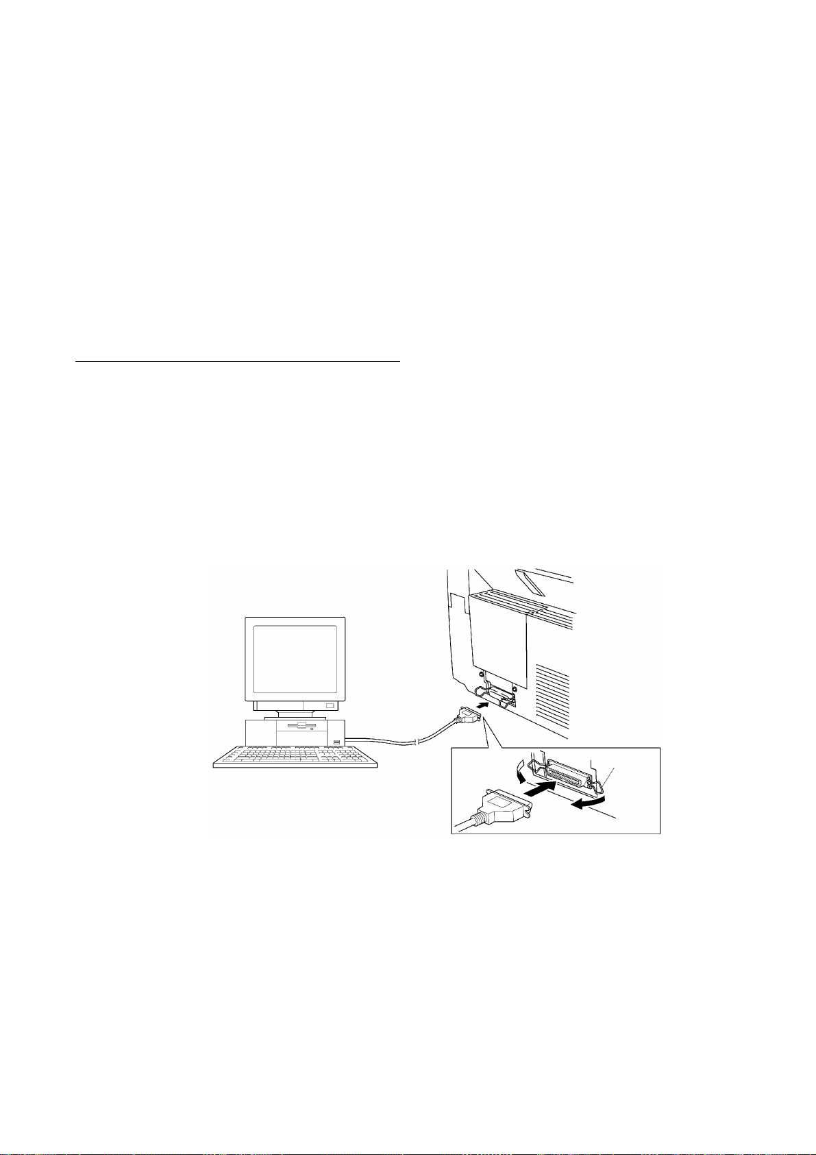
Connecting the equipment to your computer
(1) Make sure that the equipment's power cord is unplugged from a wall socket.
(2) Make sure that your computer is powered off.
(3) Connect the interface cable to the parallel interface port on the back of the equipment and
secure it with the lock wires.
(4) Connect the other end of the interface cable to the printer port of your computer and secure
it with the two screws.
(5) Power on your computer.
(6) Plug the equipment's power cord into a wall socket.
Host computer
Interface cable
Lock
wires
II - 1

Installing the update data onto the flash ROM of the facsimile equipment
(1) Load the floppy disk which stores the update data and transfer utility into the floppy disk
drive of your computer.
(Or, copy the update data and transfer utility onto the same directory of the hard disk.)
(2) Click the Start button, point to Programs, and then click MS-DOS Prompt to open an MS-
DOS window.
(3) Type the drive letter where the update data and transfer utility are located. If it is a floppy
disk drive, type A:\ from the command line and press the ENTER key.
(4) Check that your computer is connected with the facsimile equipment correctly.
(5) To start the transfer utility transmitting the update data to the flash ROM of the facsimile
equipment, type the following:
A:\ICEN filename /b
Then press the ENTER key.
The equipment beeps and shows the "CONNECTING" on the LCD for one second.
Then, the equipment shows the "DOWNLOADING" on the LCD and starts receiving data
downloaded from the host computer.
During downloading, the equipment beeps intermittently.
Upon completion of the downloading, the equipment beeps continuously.
II - 2

CHAPTER III.
THEORY OF OPERATION

CONTENTS
1. OVERVIEW.....................................................................................................III-1
2. MECHANISMS................................................................................................III-2
2.1Scanner Mechanism.............................................................................. III-3
2.1.1Document feeding and ejecting mechanism................................... III-3
2.1.2Document scanning mechanism..................................................... III-3
2.2Laser Printing Mechanism...................................................................... III-4
2.2.1Paper pulling-in, registration, feeding, and ejecting mechanism..... III-4
2.2.2Print process mechanism................................................................ III-6
(1) Charging process.................................................................... III-7
(2) Exposing process.................................................................... III-7
(3) Developing process................................................................. III-8
(4) Transferring process................................................................ III-8
(5) Erasing process....................................................................... III-8
2.2.3Heat-fixing mechanism................................................................... III-9
2.3Sensors and Actuators........................................................................... III-10
3. CONTROL ELECTRONICS........................................................................... III-12
3.1Configuration...........................................................................................III-12
3.2Main PCB................................................................................................III-13
3.3Relay PCB..............................................................................................III-23
3.4NCU PCB................................................................................................III-24
3.5Control Panel PCB................................................................................. III-27
3.6Power Supply PCBs............................................................................... III-28
[ 1 ]Low-voltage power supply PCB.................................................. III-28
[ 2 ]High-voltage power supply PCB................................................. III-29
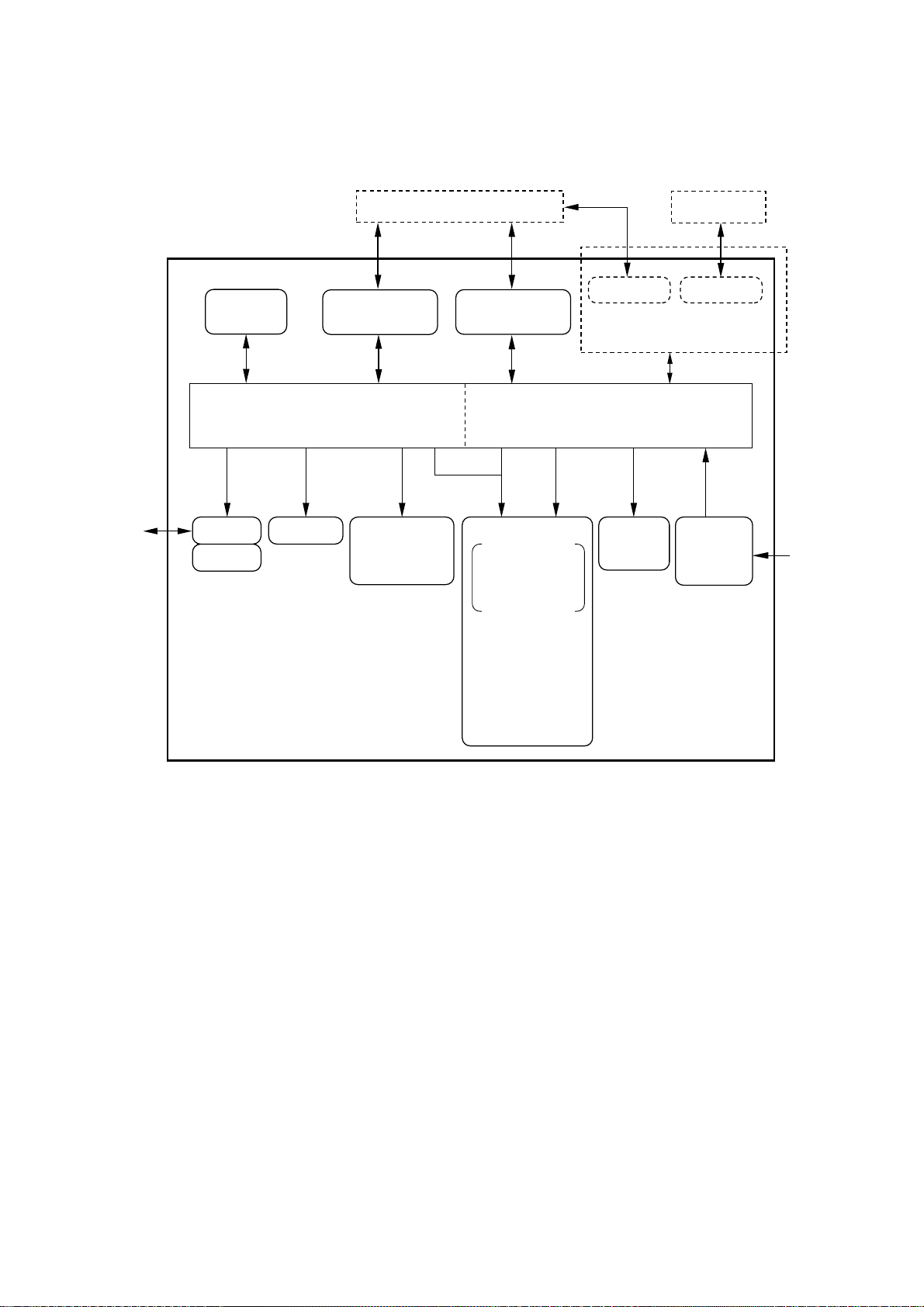
1. OVERVIEW
Line
Control
panel
NCU
Handset
PC/AT
RS-232C RS-422
RS-232C
(Modular connector)
[FAX3550/3650/
8000P/8200P]
Centronics
parallel interface
[MFC4450/
4550/4550plus/
6550MC/7550MC/7650MC/
9000/9500]
Optional serial interface
(Extended I/O connector)
[MFC6550MC/7550MC/
7650MC/9000/9500]
Fax Control Section Laser Printing Control Section
Printer
data
Laser printing unit
Charging, exposing,
developing,
transferring, erasing,
and heat-fixing
processes
- Electrical charger
- Laser unit
(including the polygon
motor)
- Laser-sensitive drum
- Developer roller
- Transfer roller
- Eraser lamp
- Heater roller
- Main motor
Paper
feeding
mechanism
Low- and
high-voltage
power
supplies
Speaker
Scanner unit
- LED array
- CCD unit
- Scanner motor
Fax data
MAC
AC
III – 1

2. MECHANISMS
The equipment is classified into the following mechanisms:
■ SCANNER MECHANISM – Document feeding and ejecting mechanism
■ LASER PRINTING MECHANISM – Paper pulling-in, registration, feeding, and
■ SENSORS AND ACTUA TORS
Paper pulling-in and
registration mechanism
– Document scanning mechanism
ejecting mechanisms
– Print process mechanism (consisting of
charging, exposing, developing, transferring,
and erasing processes)
– Heat-fixing mechanism
Document feeding
and ejecting mechanism
Document scanning
mechanism
Paper ejecting mechanism
Heat-fixing mechanism
Print process mechanism
LASER PRINTING
MECHANISM
SCANNER
MECHANISM
With paper feeding
mechanism
III – 2
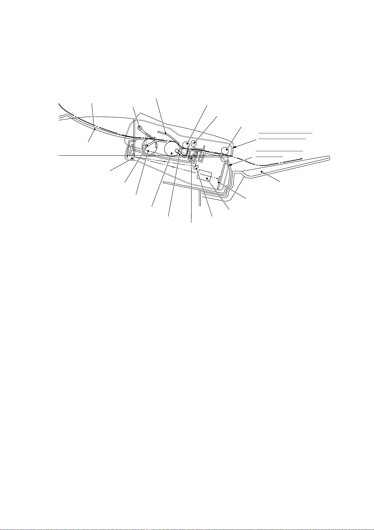
2.1 Scanner Mechanism
Document
Document stacker
2nd mirror
Document front sensor actuator
Document take-in roller ASSY
Separation roller ASSY
Document rear sensor actuator
Nip-related
parts
ADF parts
LED array
2.1.1 Document feeding and ejecting mechanism
Document feed roller ASSY
Document pressure bar
Document ejection roller ASSY
Document feeding and
ejecting mechanism
Document scanning
mechanism
CCD unit
Lens
1st mirror
Document tray
(Front)
This mechanism consists of the document stacker, automatic document feeder (ADF), document feed roller ASSY, and document sensors. (For details about the sensors, refer to Section 2.3.)
If the operator sets documents on the document stacker and starts the scanning operation,
the scanner motor rotates so that the ADF (which consists of the document take-in roller
ASSY, separation roller ASSY, ADF parts and nip-related parts) feeds those documents into
the equipment, starting from the bottom sheet to the top, page by page. Each document
advances with the document feed roller ASSY to the scanner, and then it is fed out of the
equipment with the document ejection roller ASSY.
2.1.2 Document scanning mechanism
The scanner uses a charge coupled device (CCD) image sensor.
As illustrated above, the LED array illuminates a document and the reflected light of the
scanned image data is transmitted via the mirrors into the lens which reduces the scanned
data so as to form the image on the CCD.
III – 3
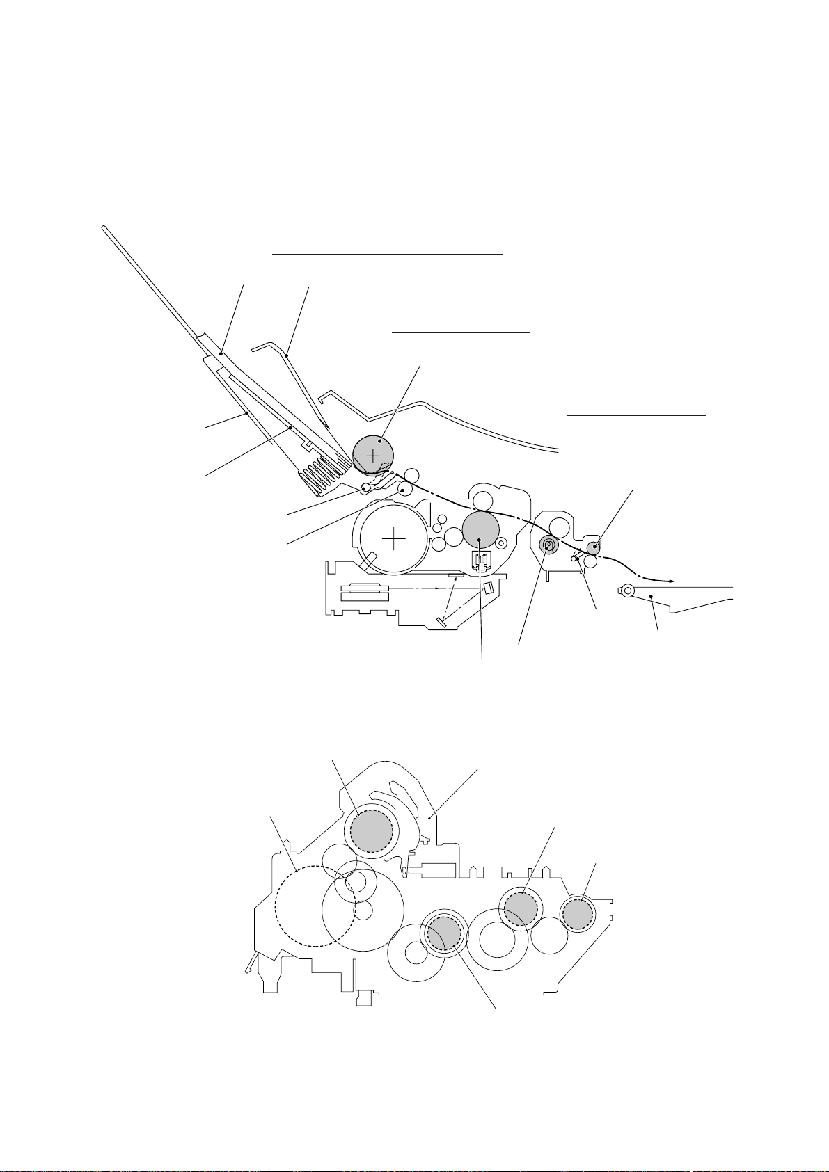
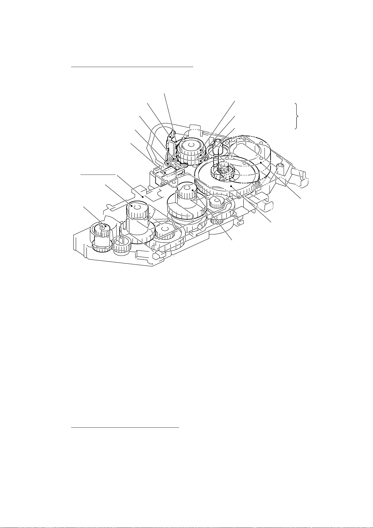
2.2 Laser Printing Mechanism
2.2.1 Paper pulling-in, registration, feeding, and ejecting mechanism
Paper pulling-in and registration mechanism
Paper
Multi-purpose
sheet feeder
Hopper
Registration sensor actuator
Registration roller
Sheet feeder cover
Paper feeding mechanism
Pull-in roller
Paper ejecting mechanism
Paper ejection roller
Paper ejection
sensor actuator
Paper tray
Heater roller
Laser-sensitive drum
Pull-in roller drive gear
Main motor
Gear drive unit
Heater roller drive gear
Paper ejection
roller drive gear
Drum drive gear
III – 4
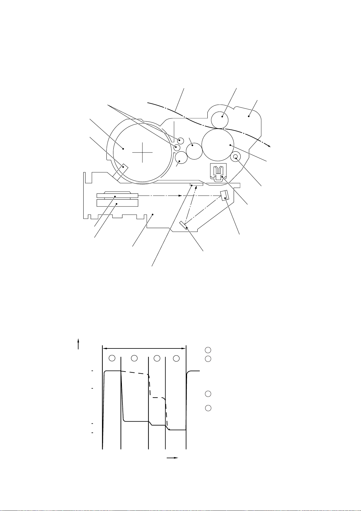
Paper pulling-in and registration mechanism
Solenoid lever
Paper feed solenoid
Gear drive unit
Heater roller drive gear
Paper ejection
roller drive gear
Clutch release lever
Solenoid spring
Clutch spring
Pull-in roller drive gear
Intermediate gear
Clutch gear
Gear 20/90
Drum drive gear
Planetary
gear
system
(Front)
Main motor
The paper pulling-in and registration mechanism consists of the pull-in roller gear (incorporated in the multi-purpose sheet feeder), planetary gear system, paper feed solenoid, solenoid lever, clutch release lever, and registration sensor. (For the details about the sensor,
refer to Section 2.3.)
If the main motor rotates clockwise, the rotation is transmitted to the intermediate gear of the
planetary gear system. As the intermediate gear rotates, the pull-in roller drive gear also rotates since the clutch gear is locked by the solenoid lever and the clutch release lever. Accordingly, the pull-in roller in the multi-purpose sheet feeder rotates to pull in paper into the
equipment, a sheet at a time.
If the paper feed solenoid is retracted and the clutch release lever is operated according to
the cam profile of the pull-in roller gear so as to release the clutch gear, the clutch gear rotates and the pull-in roller drive gear does not rotate. In this way, the clutch gear switches
the transmission of the motor rotation on and off to the pull-in roller drive gear.
The solenoid on/off timing and the clutch release lever timing allow this mechanism to pull in
a sheet and register it against the registration roller.
Paper feeding and ejecting mechanism
If the main motor rotates clockwise, the rotation is transmitted via the gear train to the drum
drive gear, heater roller drive gear, and paper ejection roller drive gear.
After the paper passes through the heat-fixing process, it will be ejected onto the paper tray.
If the leading edge of the paper pushes up the actuator of the paper ejection sensor, the
photo sensor becomes opened, signaling the start of paper ejection. If the trailing edge has
passed through the sensor actuator, the sensor becomes closed, signaling the completion of
paper ejection. Then, the main motor stops rotation.
III – 5
2.2.2 Print process mechanism
Toner augers
Toner cartridge
Toner sensor
Polygon mirror
Polygon motor
Laser unit
Paper
Developer
roller
Toner supply
roller
Transfer roller
Drum unit
Laser-sensitive drum
Cleaner roller
Charger (Corona wire)
Mirror
Mirror
Cover glass
The print process unit works with laser beam, electrical charges, and toner. The graph below shows the transition of electrical charge on the surface of the laser-sensitive drum
through the five processes: charging, exposing, developing, transferring, and erasing processes.
A single cycle of laser-sensitive
drum operation
1 Charges the drum surface positively .
1
+1000
+700
+400
+300
Electrical charge on the drum surface (V)
(a)
(b)
2
3
4
2 Exposes the drum surface to a laser beam to
form a latent image and develops the latent
image with toner.
(a) Unexposed area (Non-image area)
(b) Exposed area (Image area)
3 Transfers the toner-formed image from the
drum to paper.
4 Erases the residual potential.
Time
III – 6
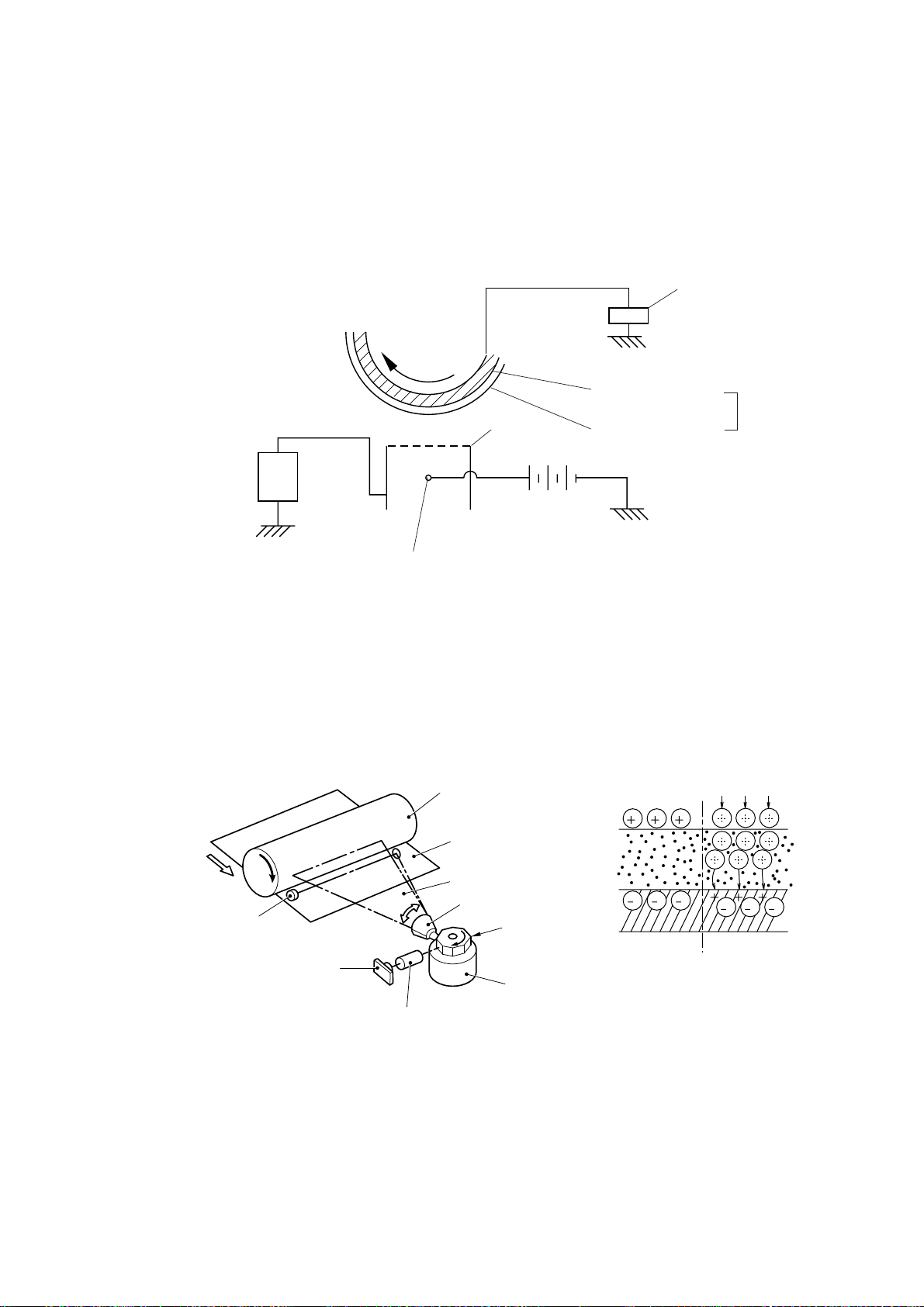
(1) Charging process
The high-voltage power supply applies DC bias to the corona wire to generate ion on the
grid. The ion uniformly charges the surface of the laser-sensitive drum to approx. 1000V
which is kept by the varister grounding the grid to the frame.
Varister
+
+
+
Approx. 1000V
Approx. 280V
-
-
-
-
-
+
+
-
-
-
---
+
+
+
+
+
+
+
Corona wire
+
+
+
+
+
+
+
+
+
Grid
High-voltage
power source
Aluminum drum
Laser-sensitive layer
Positive charging
source
Drum
(2) Exposing process
When the laser-sensitive drum holds a positive electrical charge, the laser beam issued from
the laser unit scans the drum according to the print image to expose the drum surface for
neutralizing the spots where black should be, forming an electrostatic latent image.
Laser detector
Laser diode
Laser-sensitive drum
Paper
Laser beam
f θ lens
Lens
Laser beam
Polygon mirror
Polygon motor
III – 7
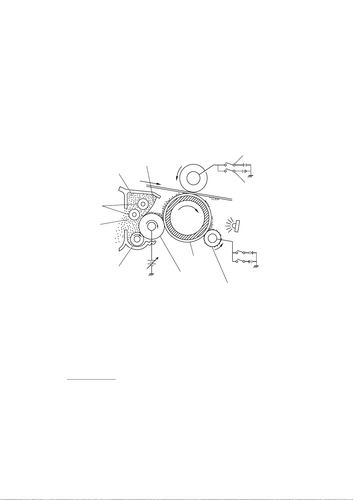
(3) Developing process
The developing process develops an electrostatic latent image formed on the drum in the
exposing process, into a toner image.
The developer roller attracts the toner particles fed from the toner cartridge by the toner supply roller, and then conveys them to the contact section with the laser-sensitive drum.
On the contact section between the developer roller and drum, the positive toner particles
stick to the neutralized spots on the drum according to the principles of attraction and repulsion, transforming a latent image into a toner image.
The toner augers (which agitate toner particles in the chamber) and the blade allow toner
particles to be fed onto the developer roller at an even thickness.
Switch “a” (ON for the
transfer process)
Switch “b” (ON for repulsing
toner from the transfer roller)
Toner augers
Chamber
Blade
Transfer roller
Toner
Toner supply roller
DC bias
Laser-sensitive
drum
Developer
roller
Eraser lamp
Cleaner roller
(4) Transferring process
When a paper passes between the drum and the transfer roller, the switch “a” (see the
above illustration) is turned on to negatively charge the transfer roller. The toner is positive,
so the toner image formed on the drum will be transferred onto the paper according to the
same principle as for the developing process.
If the toner image fails to stick to the paper due to paper jam or other errors, it will stick to the
transfer roller. To repulse this toner, the switch “b” (see the above illustration) is turned on to
positively charge the transfer roller. The toner returns from the transfer roller to the drum.
Cleaning the drum
In the transferring process, not all the toner particles on the drum are transferred onto the
paper but some toner particles remain on the drum. The cleaner roller cleans the drum surface and collects the residual toner. When printing starts or during non-printing, the toner
collected on the cleaner roller will be discharged onto the drum and returned to the chamber
through the developer roller for recycling in the subsequent developing process.
(5) Erasing process
The eraser lamp emits light to expose the drum surface, which erases the residual electrical
charge.
III – 8

2.2.3 Heat-fixing mechanism
Pressure roller
Heater roller
(including the FU lamp)
Heat-fixing unit
(Paper ejection roller)
Paper
(Paper ejection sensor actuator)
As the paper passes between the heater roller and the pressure roller in the fixing unit, the
heater roller fuses the toner on the paper.
III – 9

2.3 Sensors and Actuators
This equipment has ten sensors: two microswitches, six photosensors and two thermisters
as described below.
Sensor name Type Located on
Hook switch sensor Microswitch Hook switch PCB
Cover sensor Microswitch Relay PCB
Registration sensor Photosensor (PC1) Relay PCB
Sheet feeder cover sensor Photosensor (PC2) Relay PCB
Paper ejection sensor Photosensor (PC1) High-voltage power supply PCB
Document front sensor Photosensor (PC1) Document sensor PCB
Document rear sensor Photosensor (PC2) Document sensor PCB
Toner sensor Photosensor (PH1) Toner sensor PCB (on the laser unit)
Toner thermister P1 Toner sensor PCB (on the laser unit)
Heater thermister __ Fixing unit
• Hook switch sensor which detects whether the handset is placed on the handset mount.
• Cover sensor which detects whether the top cover is closed.
• Registration sensor which detects the leading and trailing edges of paper, which allows
the controller to determine the registration timing and check paper jam.
• Sheet feeder cover sensor which detects whether the sheet feeder cover is closed.
• Paper ejection sensor which detects whether the recording paper goes out of the equipment.
• Document front sensor which detects the presence of documents.
• Document rear sensor which detects the leading and trailing edges of pages to tell the
control circuitry when the leading edge of a new page has reached the starting position
and when the scan for that page is over.
• Toner sensor which detects whether there is toner or a toner cartridge is loaded.
• Toner thermister which detects the temperature of the toner cartridge.
• Heater thermister which detects the temperature of the heater roller of the fixing unit.
These photosensors are a photointerrupter consisting of a light-emitting diode and a lightsensitive transistor. Each of them has an actuator separately arranged as shown on the next
page.
III – 10
Registration sensor actuator
Registration sensor (Photosensor)
(Main PCB)
Toner thermister
(On back of PCB)
Toner sensor
(Low-voltage power
supply PCB)
Hook switch sensor
(Microswitch)
Hook switch sensor
actuator
(Eraser lamp board)
Document front sensor actuator
Document front sensor (Photosensor)
(Document sensor PCB)
(Relay PCB)
(Toner
sensor
PCB)
(Fixing unit)
Sheet feeder cover sensor actuator
Sheet feeder cover sensor
(Photosensor)
Cover sensor actuator
Cover sensor (Microswitch)
(High-voltage power
supply PCB)
Paper ejection sensor
actuator
Paper ejection sensor
(Photosensor)
Heater thermister
Document rear sensor actuator
Document rear sensor
(Photosensor)
Location of Sensors and Actuators
III – 11
 Loading...