


 Loading...
FACSIMILE EQUIPMENT
SERVICE MANUAL
MODELS: MFC-8460N/8860DN/8870DW
DCP-8060/8065DN
Confidential
© Copyright Brother 2006 All rights reserved.
No part of this publication may be reproduced in any form or by any means without permission in writing from the publisher.
Specifications are subject to change without notice.
Confidential
PREFACE
This Service Manual is intended for use by service personnel and details the specifications, construction, theory of operation, and maintenance for the Brother machines noted on the front cover. It includes information required for troubleshooting and service--disassembly, reassembly, and lubrication--so that service personnel will be able to understand equipment function, repair the equipment in a timely manner and order spare parts as necessary.
To perform appropriate maintenance so that the machine is always in the best possible condition for the customer, service personnel must adequately understand and apply this manual.
HOW THIS MANUAL IS ORGANIZED
This manual is made up of nine chapters and appendices.
CHAPTER 1 PARTS NAMES AND FUNCTIONS
Contains external views and names of components and describes their functions. Information about the keys on the control panel is included to help you check operation or make adjustments.
CHAPTER 2 SPECIFICATIONS
Lists the specifications of each model, which enables you to make a comparison of different models.
CHAPTER 3 THEORY OF OPERATION
Gives an overview of the scanning and printing mechanisms as well as the sensors, actuators, and control electronics. It aids in understanding the basic principles of operation as well as locating defects for troubleshooting.
CHAPTER 4 TRANSFER OF DATA LEFT IN THE MACHINE TO BE SENT FOR REPAIR
Describes how to transfer data left in the machine to be sent for repair. The service personnel should instruct end users to follow the transfer procedure given in this chapter if the machine at the user site cannot print received data due to the printing mechanism defective. End users can transfer received data to another machine to prevent data loss.
CHAPTER 5 DISASSEMBLY/REASSEMBLY AND LUBRICATION
Details procedures for disassembling and reassembling the machine together with related notes. The disassembly order flow provided enables you to see at a glance the quickest way to get to component(s) involved.
At the start of a disassembly job, you check a disassembly order flow that guides you through a shortcut to the object components.
This chapter also covers screw tightening torques and lubrication points to which the specified lubricants should be applied during reassembly jobs.
CHAPTER 6 ADJUSTMENTS AND UPDATING OF SETTINGS REQUIRED AFTER PARTS REPLACEMENT
Details adjustments and updating of settings, which are required if the head/carriage unit, main PCB and some other parts have been replaced.
CHAPTER 7 CLEANING
Provides cleaning procedures not covered by the User's Manual. Before starting any repair work, clean the machine as it may solve the problem concerned.
i |
Confidential |
CHAPTER 8 MAINTENANCE MODE
Describes the maintenance mode which is exclusively designed for the purpose of checks, settings and adjustments using the keys on the control panel.
In the maintenance mode, you can update memory (EEPROM: electrically erasable programmable read-only memory) contents for optimizing the drive conditions of the head/carriage unit, paper feed roller or paper ejection roller (if they have been replaced) or for setting the CCD scanner area, for example. You can also customize the EEPROM according to the shipment destination of the machine concerned. In addition, you can perform operational checks of the LCD, control panel PCB or sensors, perform a print test, display the log information or error codes, and modify firmware switches (WSW).
CHAPTER 9 ERROR INDICATION AND TROUBLESHOOTING
Details error messages and codes that the incorporated self-diagnostic functions display if any error or malfunction occurs. If any error message appears, refer to this chapter to find which components should be checked or replaced.
The latter half of this chapter provides sample problems that could occur in the main sections of the machine and related troubleshooting procedures. This will help service personnel pinpoint and repair defective components.
APPENDIX 1 SERIAL NUMBERING SYSTEM
Shows the location of serial number labels put on some parts and lists the coding information pertaining to the serial numbers.
APPENDIX 2 FIRMWARE INSTALLATION
Provides instructions on how to update firmware stored in the flash ROM on the main PCB or load firmware to a new main PCB from the host PC.
No hardware replacement is required for updating.
APPENDIX 3 CUSTOMIZING CODES ACCORDING TO SHIPPING DESTINATION
Lists the customizing codes for the various preferences exclusively designed for each destination (e.g. language). Those codes are stored in the memory (EEPROM) mounted on the main PCB. If the main PCB is replaced with a new one, therefore, you will need to set the proper customizing codes with the machine in the maintenance mode.
APPENDIX 4 FIRMWARE SWITCHES (WSW)
Describes the functions of the firmware switches, which can be divided into two groups: one is for customizing preferences designed for the shipping destination (as described in Appendix 3) and the other is for modifying preferences that match the machine to the environmental conditions. Use the latter group if the machine malfunctions due to mismatching.
APPENDIX 5 WIRING DIAGRAM
Provides the wiring diagram that helps you understand the connections between PCBs.
APPENDIX 6 CIRCUIT DIAGRAMS
Provides the circuit diagrams of the NCU PCB and power supply PCB.
APPENDIX 7 VIEWING THE EVENT LOG FILE
When installing the printer driver, the installer logs events that occur during the installation process in the event log file. This appendix views a sample of the event log file. Selecting Start | Program | Brother | MFL-Pro Suite model name | Installation Diagnostics reads out the event log file.
This manual describes the models and their versions destined for major countries.
The specifications and functions are subject to change depending upon each destination.
ii |
Confidential |
TABLE OF CONTENTS
CHAPTER 1 PARTS NAMES & FUNCTIONS |
|
|||
1.1 |
EQUIPMENT OUTLINE............................................................................................. |
1-1 |
||
1.2 |
CONTROL PANEL .................................................................................................... |
1-2 |
||
1.3 |
COMPONENTS ......................................................................................................... |
1-7 |
||
CHAPTER 2 |
SPECIFICATIONS |
|
||
2.1 |
GENERAL.................................................................................................................. |
2-1 |
||
2.1.1 |
General Specifications ......................................................................................... |
2-1 |
||
2.1.2 |
Paper Specifications............................................................................................. |
2-2 |
||
|
2.1.2.1 |
Paper handling ............................................................................................... |
2-2 |
|
|
2.1.2.2 |
Media specifications ....................................................................................... |
2-2 |
|
2.1.3 |
Printable Area ................................................................................................................ |
2-5 |
||
|
2.1.3.1 PCL5e/EPSON/IBM emulation....................................................................... |
2-5 |
||
|
2.1.3.2 |
PCLXL, PS (BR-Script 3)................................................................................ |
2-8 |
|
2.1.4 Print Speeds with Various Settings............................................................................. |
2-9 |
|||
2.1.5 Toner Cartridge Weight Information ......................................................................... |
2-10 |
|||
2.2 |
SPECIFICATIONS LIST .......................................................................................... |
2-11 |
||
CHAPTER 3 THEORY OF OPERATION |
|
|||
3.1 |
OVERVIEW................................................................................................................ |
3-1 |
||
3.2 |
MECHANICAL COMPONENTS ................................................................................ |
3-2 |
||
3.2.1 |
Scanner Mechanism ............................................................................................ |
3-3 |
||
3.2.2 |
Overview of Gear ................................................................................................. |
3-9 |
||
3.2.3 |
Paper Transfer ................................................................................................... |
3-10 |
||
|
3.2.3.1 |
Paper supply .............................................................................................. |
3-10 |
|
|
3.2.3.2 |
Paper registration....................................................................................... |
3-12 |
|
|
3.2.3.3 |
Drum unit.................................................................................................... |
3-12 |
|
|
3.2.3.4 |
Developing ................................................................................................. |
3-13 |
|
|
3.2.3.5 |
Fixing stage................................................................................................ |
3-14 |
|
|
3.2.3.6 |
Paper eject ................................................................................................. |
3-15 |
|
|
3.2.3.7 Duplex printing (For the models with the DX only)..................................... |
3-16 |
||
iii |
Confidential |
|
3.2.3.8 Paper feeding from the MP tray ................................................................. |
3-17 |
||
|
3.2.3.9 |
LT tray ........................................................................................................ |
3-17 |
|
3.2.4 |
Toner Cartridge .................................................................................................. |
3-18 |
||
|
3.2.4.1 Toner life end mode ................................................................................... |
3-18 |
||
|
3.2.4.2 New toner detection mechanism................................................................ |
3-20 |
||
|
3.2.4.3 Counter reset during indication of “Toner Life End” ................................... |
3-21 |
||
3.2.5 |
Print Process ...................................................................................................... |
3-22 |
||
|
3.2.5.1 |
Charging ..................................................................................................... |
3-22 |
|
|
3.2.5.2 |
Exposure stage .......................................................................................... |
3-22 |
|
|
3.2.5.3 |
Transfer ...................................................................................................... |
3-23 |
|
3.2.6 |
Sensors .............................................................................................................. |
3-24 |
||
3.3 |
CONTROL ELECTRONICS .................................................................................... |
3-25 |
||
3.3.1 |
Components....................................................................................................... |
3-25 |
||
CHAPTER 4 TRANSFER OF DATA LEFT IN THE MACHINE TO BE SENT FOR REPAIR |
||||
4.1 TRANSFERRING RECEIVED FAX DATA ................................................................ |
4-1 |
|||
CHAPTER 5 DISASSEMBLY/REASSEMBLY AND LUBRICATION |
|
|||
5.1 |
DISASSEMBLY/REASSEMBLY ............................................................................... |
5-1 |
||
Safety Precautions............................................................................................................ |
5-1 |
|||
Tightening Torque ............................................................................................................ |
5-2 |
|||
Harness Routing............................................................................................................... |
5-4 |
|||
Preparation |
..................................................................................................................... |
5-21 |
||
How to Access the Object Component........................................................................... |
5-21 |
|||
Disassembly Flowchart................................................................................................... |
5-22 |
|||
5.1.1 |
AC Cord.............................................................................................................. |
5-23 |
||
5.1.2 |
Drum/Toner ..............................................................................................ASSY |
5-23 |
||
5.1.3 DX Feed ............................................ASSY (For the models with the DX only) |
5-24 |
|||
5.1.4 |
Paper ..........................................................................................................Tray |
5-24 |
||
5.1.5 |
Back .........................................................................................................Cover |
5-27 |
||
5.1.6 DX Blank ...........................................Cover (For models with out the DX only) |
5-27 |
|||
5.1.7 |
Outer .............................................................................................Chute ASSY |
5-28 |
||
iv |
Confidential |
5.1.8 |
Access Cover/Side Cover L ............................................................................... |
5-30 |
5.1.9 |
ADF Unit............................................................................................................. |
5-31 |
5.1.10 |
Hinge Base R ..................................................................................................... |
5-32 |
5.1.11 |
Hinge Arm R....................................................................................................... |
5-33 |
5.1.12 |
Hinge ASSY L..................................................................................................... |
5-33 |
5.1.13 |
ADF Cover ASSY ............................................................................................... |
5-34 |
5.1.14 |
ADF Side Cover F .............................................................................................. |
5-34 |
5.1.15 |
ADF Side Cover R.............................................................................................. |
5-35 |
5.1.16 |
ADF Chute ASSY ............................................................................................... |
5-36 |
5.1.17 |
SB Chute ASSY (For the models with the DX only) / |
|
|
SX Chute (For the models with out the DX only) ............................................... |
5-38 |
5.1.18 |
Exit Chute Cover ASSY...................................................................................... |
5-38 |
5.1.19 |
Earth Spring ....................................................................................................... |
5-39 |
5.1.20 |
PF Roller Holder ASSY ...................................................................................... |
5-40 |
5.1.21 |
LF Roller 1 ASSY ............................................................................................... |
5-41 |
5.1.22 |
SB Roller ASSY (For the models with the DX only) ........................................... |
5-42 |
5.1.23 |
ADF Motor .......................................................................................................... |
5-44 |
5.1.24 |
SB Solenoid ASSY (For the models with the DX only)....................................... |
5-45 |
5.1.25 |
PF Solenoid ASSY (For the models with the DX only)....................................... |
5-45 |
5.1.26 |
ADF Relay PCB.................................................................................................. |
5-46 |
5.1.27 |
Paper Feed Chute ASSY ................................................................................... |
5-47 |
5.1.28 |
Actuator Front 1/Photo Interrupter |
|
|
(For the models with the DX only)...................................................................... |
5-48 |
5.1.29 |
Actuator Front 2/Photo Interrupter |
|
|
(For the models with the DX only)...................................................................... |
5-49 |
5.1.30 ADF Film/Spring Plate ADF Front A ASSY/Separation Rubber/Rubber Holder/ |
||
|
Separation Spring............................................................................................... |
5-50 |
5.1.31 |
Pressure Roller/LF Spring.................................................................................. |
5-50 |
5.1.32 |
LF Roller 2 ASSY ............................................................................................... |
5-51 |
5.1.33 |
Exit Roller ASSY................................................................................................. |
5-52 |
5.1.34 |
LF Roller 3 ASSY ............................................................................................... |
5-53 |
5.1.35 |
LF Roller 4 ASSY ............................................................................................... |
5-54 |
5.1.36 |
Flap A ASSY (For the models with the DX only)/ |
|
|
Flap A (For models with out the DX only)........................................................... |
5-55 |
|
v |
Confidential |
5.1.37 Document Hold/Document Hold Spring ............................................................. |
5-56 |
|
5.1.38 Upper Main Chute ASSY/Lower Main Chute ASSY........................................... |
5-56 |
|
5.1.39 |
Actuator R/Photo Interrupter .............................................................................. |
5-58 |
5.1.40 |
Flap B ................................................................................................................. |
5-59 |
5.1.41 Actuator SB/Photo Interrupter (For the models with the DX only)...................... |
5-59 |
|
5.1.42 |
Document Ejection Tray..................................................................................... |
5-60 |
5.1.43 |
Document Cover Sensor.................................................................................... |
5-61 |
5.1.44 |
Eject Roller B4.................................................................................................... |
5-61 |
5.1.45 |
Presser Roller..................................................................................................... |
5-62 |
5.1.46 |
Panel Cover ASSY ............................................................................................. |
5-63 |
5.1.47 |
Scanner Unit ASSY ............................................................................................ |
5-64 |
5.1.48 |
Top Cover ASSY ................................................................................................ |
5-65 |
5.1.49 Lock Lever B/Lock Lever ASSY ......................................................................... |
5-65 |
|
5.1.50 |
CCD Module....................................................................................................... |
5-66 |
5.1.51 |
FFC Cable ASSY ............................................................................................... |
5-68 |
5.1.52 |
Scanner Motor FB .............................................................................................. |
5-69 |
5.1.53 |
Pulley ASSY ....................................................................................................... |
5-70 |
5.1.54 |
Photo Interrupter ................................................................................................ |
5-70 |
5.1.55 |
Panel Unit........................................................................................................... |
5-71 |
5.1.56 |
Panel PCB ASSY ............................................................................................... |
5-72 |
5.1.57 |
Printed Rubber Key ............................................................................................ |
5-73 |
5.1.58 |
LCD Cover/Backlight Module/LCD ..................................................................... |
5-74 |
5.1.59 NCU PCB ASSY (For the models with the NCU only) ....................................... |
5-75 |
|
5.1.60 |
Speaker ASSY ................................................................................................... |
5-77 |
5.1.61 |
Driver PCB ......................................................................................................... |
5-78 |
5.1.62 |
Fuser Unit........................................................................................................... |
5-79 |
5.1.63 |
Tray MP ASSY ................................................................................................... |
5-81 |
5.1.64 MP Tray Cover ASSY/Process Cover ASSY...................................................... |
5-82 |
|
5.1.65 |
Main PCB ........................................................................................................... |
5-85 |
5.1.66 Gear Plate Calking ASSY AL/Develop Joint/Main Motor ASSY AL.................... |
5-86 |
|
5.1.67 |
Main Shield Plate ASSY..................................................................................... |
5-88 |
vi |
Confidential |
5.1.68 |
Relay Rear PCB ASSY/Connector ..................................................................... |
5-90 |
5.1.69 |
Relay Front PCB ASSY...................................................................................... |
5-92 |
5.1.70 |
MP Solenoid ASSY............................................................................................. |
5-93 |
5.1.71 |
Drive Release Link ............................................................................................. |
5-94 |
5.1.72 |
T1 Solenoid ASSY.............................................................................................. |
5-95 |
5.1.73 |
Toner Sensor PCB ............................................................................................. |
5-95 |
5.1.74 |
Register Solenoid ASSY..................................................................................... |
5-96 |
5.1.75 |
Ejector Solenoid ASSY (For the models with the DX only) ................................ |
5-96 |
5.1.76 |
Interlock SW ASSY ............................................................................................ |
5-97 |
5.1.77 |
New Toner Actuator ........................................................................................... |
5-97 |
5.1.78 |
Gear 17/20 ......................................................................................................... |
5-98 |
5.1.79 |
Thermistor ASSY.............................................................................................. |
5-100 |
5.1.80 |
Side Cover R .................................................................................................... |
5-100 |
5.1.81 |
Joint Cover ASSY............................................................................................. |
5-101 |
5.1.82 |
Filter ................................................................................................................. |
5-102 |
5.1.83 |
Laser Unit ......................................................................................................... |
5-103 |
5.1.84 |
PS PCB Unit..................................................................................................... |
5-104 |
5.1.85 |
High-Voltage PS PCB ASSY............................................................................ |
5-107 |
5.1.86 |
Toner LED PCB Unit ASSY.............................................................................. |
5-109 |
5.1.87 |
Fan Motor 60 Unit............................................................................................. |
5-110 |
5.1.88 |
Fan Motor 60 Unit LV ....................................................................................... |
5-110 |
5.1.89 |
Frame L............................................................................................................ |
5-111 |
5.1.90 |
Frame R ........................................................................................................... |
5-111 |
5.1.91 |
MP Unit............................................................................................................. |
5-112 |
5.1.92 |
Regist Actuator Rear/Regist Actuator Spring................................................... |
5-117 |
5.1.93 |
Regist Actuator Front/Regist Actuator Spring .................................................. |
5-119 |
5.1.94 |
Roller Holder ASSY.......................................................................................... |
5-120 |
5.1.95 |
PE Actuator, Edge Actuator, Edge Actuator Spring ......................................... |
5-121 |
5.1.96 |
PE PG Sensor ASSY ....................................................................................... |
5-123 |
5.1.97 |
Wireless PCB (PCB T60H929.00 ASSY 02) (For the model with the Wireless only)5-124 |
|
5.2 DISASSEMBLY/REASSEMBLY (LT-5300) .......................................................... |
5-125 |
|
5.2.1 |
Paper Tray........................................................................................................ |
5-125 |
|
vii |
Confidential |
5.2.2 |
LT Front Cover ASSY....................................................................................... |
5-128 |
5.2.3 |
LT Rear Cover.................................................................................................. |
5-129 |
5.2.4 |
LT Side Cover L ............................................................................................... |
5-129 |
5.2.5 |
LT Side Cover R............................................................................................... |
5-130 |
5.2.6 |
LT PCB ASSY .................................................................................................. |
5-131 |
5.2.7 |
Connector: 55533-1219.................................................................................... |
5-132 |
5.2.8 |
Connector: 54702-1219.................................................................................... |
5-132 |
5.2.9 |
Gear 24 LT ....................................................................................................... |
5-133 |
5.2.10 |
Collar 6 ............................................................................................................. |
5-134 |
5.2.11 |
LT Solenoid ASSY............................................................................................ |
5-138 |
5.2.12 |
Roller Holder ASSY.......................................................................................... |
5-139 |
5.2.13 |
Edge Actuator Spring ....................................................................................... |
5-140 |
5.2.14 |
PE Actuator, Edge Actuator ............................................................................. |
5-141 |
5.2.15 |
LT Sensor PCB ASSY...................................................................................... |
5-142 |
5.3 LUBRICATION ...................................................................................................... |
5-144 |
|
CHAPTER 6 ADJUSTMENTS AND UPDATING OF SETTINGS, REQUIRED AFTER PARTS REPLACEMENT
6.1 IF YOU REPLACE THE MAIN PCB.......................................................................... |
6-1 |
6.1.1 Load Update Programs/data ................................................................................ |
6-1 |
6.1.2 Initialize the EEPROM on the Main PCB (Function code 01)............................... |
6-1 |
6.1.3 Customize the EEPROM on the Main PCB (Function code 74)........................... |
6-1 |
6.1.4 Check the Control Panel PCB for Normal Operation (Function code 13) ............ |
6-1 |
6.1.5 Make a Sensor Operation Check (Function code 32).......................................... |
6-1 |
6.1.6Acquire of White Level Data and Set the CCD Scanner Area
|
(Function code 55) ................................................................................................. |
6-1 |
6.1.7 |
Setting the Serial Number .................................................................................... |
6-1 |
6.1.8 |
Switch Back to Standby........................................................................................ |
6-2 |
6.2 IF YOU REPLACE THE DOCUMENT SCANNER UNIT........................................... |
6-2 |
|
6.2.1Acquire of White Level Data and Set the CCD Scanner Area
|
(Function code 55) ............................................................................................... |
6-2 |
6.3 |
IF YOU REPLACE THE DRUM UNIT ....................................................................... |
6-2 |
6.4 |
PERIODICAL REPLACEMENT PARTS ................................................................... |
6-3 |
6.4.1 Periodical Replacement Parts.............................................................................. |
6-3 |
|
|
viii |
Confidential |
6.4.2 |
Procedures to Replace Periodical Replacement Parts ........................................ |
6-4 |
|
6.4.2.1 Fuser unit and laser unit............................................................................... |
6-4 |
||
6.4.2.2 Paper feeding kit for tray 1, 2 ..................................................................... |
6-32 |
||
6.4.2.3 Paper feeding kit for MP tray...................................................................... |
6-39 |
||
CHAPTER 7 |
CLEANING |
|
|
CHAPTER 8 |
MAINTENANCE MODE |
|
|
8.1 ENTRY INTO THE MAINTENANCE MODE ............................................................. |
8-1 |
||
8.2 LIST OF MAINTENANCE-MODE FUNCTIONS ....................................................... |
8-2 |
||
8.3 USER-ACCESS TO THE MAINTENANCE MODE ................................................... |
8-3 |
||
8.4 DETAILED DESCRIPTION OF MAINTENANCE-MODE FUNCTIONS.................... |
8-4 |
||
8.4.1 |
EEPROM Parameter Initialization (Function code 01/91) .................................... |
8-4 |
|
8.4.2 |
Printout of Scanning Compensation Data (Function code 05) ............................. |
8-5 |
|
8.4.3 |
Placement of CCD Unit in Position for Transportation (Function code 06).......... |
8-9 |
|
8.4.4 |
ADF Performance Test (Function code 08) ......................................................... |
8-9 |
|
8.4.5 |
Test Pattern 1 (Function code 09)...................................................................... |
8-10 |
|
8.4.6 |
Firmware Switch Setting and Printout ................................................................ |
8-11 |
|
8.4.6.1 Firmware switch setting (Function code 10) .............................................. |
8-11 |
||
8.4.6.2 Printout of firmware switch data (Function code 11).................................. |
8-13 |
||
8.4.7 |
Operation Check of LCD (Function code 12) ..................................................... |
8-14 |
|
8.4.8 |
Operational Check of Control Panel PCB (Function code 13) ........................... |
8-15 |
|
8.4.9 |
Sensor Operational Check (Function code 32) .................................................. |
8-16 |
|
8.4.10 |
Received Data Transfer Function (Function code 53) |
|
|
|
(Not applicable to DCP-8060/8065DN.)............................................................. |
8-18 |
|
8.4.11 |
Fine Adjustment of Scan Start/End Positions (Function code 54) ..................... |
8-20 |
|
8.4.12 |
Acquisition of White Level Data and CCD Scanner Area Setting |
|
|
|
(Function code 55) ............................................................................................. |
8-22 |
|
8.4.13 |
Paper Feeding and Ejecting Test (Function code 67)........................................ |
8-23 |
|
8.4.14 |
EEPROM Customizing (Function code 74)........................................................ |
8-23 |
|
8.4.15 |
Display of the Equipment’s Log Information (Function code 80)........................ |
8-24 |
|
8.4.16 |
Machine Error Code Indication (Function code 82)............................................ |
8-26 |
|
8.4.17 |
Output of Transmission Log to the Telephone Line (Function code 87) |
|
|
|
(Not applicable to DCP-8060/8065DN.)............................................................. |
8-26 |
|
|
|
ix |
Confidential |
8.4.18 |
Counter Reset After Replacing the Fuser Unit, Laser Unit and |
|
||
|
|
Paper Feed Kit (Function code 88).................................................................... |
8-27 |
|
8.4.19 Cancellation of the Memory Security Mode |
|
|||
|
|
(Not applicable to with out the NCU models and the Japanese model.) ........... |
8-27 |
|
CHAPTER 9 ERROR INDICATION AND TROUBLESHOOTING |
|
|||
9.1 |
ERROR INDICATION ................................................................................................ |
9-1 |
||
9.1.1 |
Equipment Errors ................................................................................................. |
9-1 |
||
|
9.1.1.1 Error messages appearing on the LCD.......................................................... |
9-1 |
||
|
9.1.1.2 Error codes shown in "MACHINE ERROR X X" messages ........................... |
9-4 |
||
9.1.2 |
Communications Errors...................................................................................... |
9-11 |
||
9.2 |
TROUBLESHOOTING ............................................................................................ |
9-15 |
||
9.2.1 |
Introduction......................................................................................................... |
9-15 |
||
9.2.2 |
Precautions ........................................................................................................ |
9-15 |
||
9.2.3 Checking Prior to Troubleshooting..................................................................... |
9-15 |
|||
9.2.4 Troubleshooting Based on Problem Type.......................................................... |
9-16 |
|||
|
9.2.4.1 |
Paper feeding problems ............................................................................... |
9-16 |
|
|
9.2.4.2 |
Software setting problems............................................................................ |
9-18 |
|
|
9.2.4.3 |
Malfunction ................................................................................................... |
9-21 |
|
|
9.2.4.4 |
Image defects............................................................................................... |
9-27 |
|
|
9.2.4.5 |
Incorrect printout........................................................................................... |
9-47 |
|
|
9.2.4.6 |
Network problem .......................................................................................... |
9-49 |
|
|
9.2.4.7 |
Troubleshooting of the control panel ............................................................ |
9-56 |
|
|
9.2.4.8 |
Troubleshooting of fax functions .................................................................. |
9-58 |
|
APPENDIX 1 SERIAL NUMBERING SYSTEM |
|
|||
APPENDIX 2 |
FIRMWARE INSTALLATION |
|
||
A2.1 INSTALLING THE UPDATE DATA TO THE MACHINE.................................. |
APP. 2-1 |
|||
A2.2 SETTING ID CODES TO MACHINES.............................................................. |
APP. 2-7 |
|||
APPENDIX 3 CUSTOMIZING CODES ACCORDING TO SHIPPING DESTINATION
x |
Confidential |
APPENDIX 4 FIRMWARE SWITCHES (WSW)
APPENDIX 5 WIRING DIAGRAM
APPENDIX 6 CIRCUIT DIAGRAMS NCU PCB
POWER SUPPLY PCB 100V
POWER SUPPLY PCB 200V
APPENDIX 7 VIEWING THE EVENT LOG FILE
APPENDIX 8 READMARKS
xi |
Confidential |
SAFETY PRECAUTIONS
To use the machine safely
Please keep these instructions for later reference and read them before attempting any maintenance.
NOTE: If there are faxes in the machine's memory, you need to print them or save them before you turn off the power and unplug the machine.
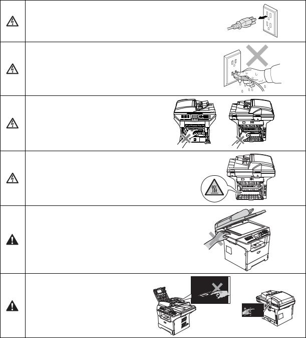
 WARNING
There are high voltage electrodes inside the machine. Before you clean the inside of the machine, make sure you have unplugged the telephone line cord first and then the power cord from the AC power outlet.
Do not handle the plug with wet hands.
Doing this might cause an electrical shock.
After you use the machine, some internal parts are extremely HOT! To prevent injuries, be careful not to put your fingers in the areas shown in the illustration.
The fuser unit is marked with a caution label.
Please do not remove or damage the label.
To prevent injuries, be careful not to put your hands on the edge of the machine under the scanner cover.
To prevent injuries, be careful not to put your fingers in the area shown in the illustrations.
Do not use a vacuum cleaner to clean up scattered toner. Doing this might cause the toner dust to ignite inside the vacuum cleaner, potentially starting a fire. Please carefully clean the toner dust with a dry, lint-free cloth and dispose of it according to local regulations.
xii |
Confidential |
 WARNING
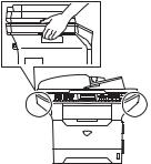
-When you move the machine, grasp the side hand holds that are under the scanner. DO NOT carry the machine by holding it at the bottom.
-Use caution when installing or modifying telephone lines. Never touch telephone wires or jack. Never install telephone wiring during a lightning storm. Never install a telephone wall jack in a wet location.
-This product must be installed near an AC power outlet that is easily accessible. In case of an emergency, you must disconnect the power cord from the AC power outlet to shut off the power completely.
-To reduce the risk of shock or fire, use only a No. 26 AWG or larger telecommunication line cord.
 CAUTION
Lightning and power surges can damage this product! We recommend that you use a quality surge protection device on the AC power line and on the telephone line, or unplug the cords during a lightning storm.
 WARNING
IMPORTANT SAFETY INSTRUCTIONS
When using your telephone equipment, basic safety precautions should always be followed to reduce the risk of fire, electric shock and injury to people, including the following:
1.Do not use this product near water, for example, near a bath tub, wash bowl, kitchen sink or washing machine, in a wet basement or near a swimming pool.
2.Avoid using this product during an electrical storm. There may be a remote risk of electric shock from lightning.
3.Do not use this product to report a gas leak in the vicinity of the leak.
4.Use only the power cord provided with the MACHINE.
SAVE THESE INSTRUCTIONS
xiii |
Confidential |
CHOOSING A LOCATION
Place your machine on a flat, stable surface that is free of vibration and shocks, such as a desk. Put the machine near a telephone wall jack and a standard, grounded AC power outlet.
Choose a location where the temperature remains between 50°F and 90.5°F (10°C and 32.5°C).
 CAUTION
-Avoid placing your machine in a high-traffic area.
-Do not place the machine near heaters, air conditioners, water, chemicals, or refrigerators.
-Do not expose the machine to direct sunlight, excessive heat, moisture, or dust.
-Do not connect your machine to an AC power outlet controlled by wall switches or automatic timers.
-Disruption of power can wipe out information in the machine’s memory.
-Do not connect your machine to an AC power outlet on the same circuit as large appliances or other equipment that might disrupt the power supply.
-Avoid interference sources, such as speakers or the base units of cordless phones.
xiv |
Confidential |
CHAPTER 1
PARTS NAMES & FUNCTIONS
Confidential
CHAPTER 1 PARTS NAMES & FUNCTIONS
This chapter contains external views and names of components and describes their functions. Information about the keys on the control panel is included to help you check operation or make adjustments.
|
|
CONTENTS |
1.1 |
EQUIPMENT OUTLINE |
...................................................................................................1-1 |
1.2 |
CONTROL PANEL........................................................................................................... |
1-2 |
1.3 |
COMPONENTS................................................................................................................ |
1-7 |
Confidential
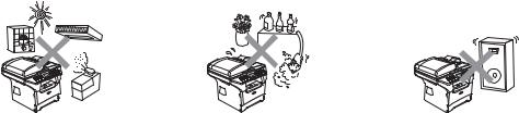
1.1 EQUIPMENT OUTLINE
Front view
Automatic Document Feeder (ADF)
Control Panel
Face-down Output Tray Support Flap with Extension (Support Flap)
Front Cover
Paper Tray
Fig. 1-1
Rear view
ADF Document Output Support Flap
Document Cover
Power Switch
AC Power Connector
Back Cover |
Parallel Interface Connector |
10/100 Baser TX Port |
USB Interface Connector |
|
Fig. 1-2
1-1 |
Confidential |
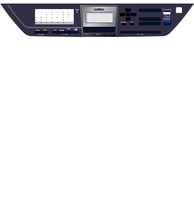
1.2 CONTROL PANEL
MFC-8460N, MFC-8860DN and MFC-8870DW have similar control keys.
1 |
|
|
|
|
2 |
3 |
4 |
|
5 |
6 |
||||||
|
|
|
|
|
|
|
|
|
|
|
|
|
|
|
|
|
|
|
|
|
|
|
|
|
|
|
|
|
|
|
|
|
|
|
|
|
|
|
|
|
|
|
|
|
|
|
|
|
|
|
|
|
|
|
|
|
|
|
|
|
|
|
|
|
|
|
|
|
|
|
|
|
|
|
|
|
|
|
|
|
|
|
|
|
|
|
|
|
|
|
|
|
|
|
|
|
|
|
|
|
|
|
|
|
|
|
|
|
|
|
|
|
|
|
|
|
|
|
|
|
|
|
|
|
|
|
|
|
|
|
|
|
|
|
|
|
|
|
|
|
|
|
|
|
|
|
|
|
|
|
|
|
11 |
10 |
9 |
8 |
7 |
|
Fig. 1-3 |
|
||
|
|
|
|
|
1. One-Touch Keys |
|
5. Dial pad Keys |
|
|
|
|
|
||
These 20 keys give you instant access to 40 |
|
Used to enter telephone and fax numbers or to |
||
previously stored numbers. |
|
|
enter text. |
|
Shift |
|
|
The [#] key temporarily switches the dialing mode |
|
|
|
from Pulse to Tone during a telephone call. |
||
Lets you access One-Touch numbers 21 to 40 when |
|
|||
held down. |
|
|
|
|
|
|
|
|
|
2. Status LED |
|
|
6. Stop/Exit Key |
|
|
|
|
||
The LED will flash and change color depending on |
|
Stops an operation or exits from a menu. |
||
the machine status. |
|
|
|
|
|
|
|
|
|
3. LCD |
|
|
7. Start Key |
|
|
|
|
||
Displays messages to help you use your machine. |
|
Starts sending a fax, making a copy or scanning. |
||
|
|
|
|
|
4. Menu Keys |
|
|
|
|
|
|
|
|
|
Menu |
|
|
|
|
Accesses the main menu. |
|
|
|
|
Clear/Back |
|
|
|
|
Deletes entered data or lets you exit the menu. |
|
|
|
|
OK |
|
|
|
|
Selects a setting. |
|
|
|
|
or |
|
|
|
|
Scrolls backwards or forwards through menu |
|
|
|
|
selections. |
|
|
|
|
Changes the volume when in fax or standby mode. |
|
|
|
|
or |
|
|
|
|
Scrolls through the menus and options. |
|
|
|
|
|
|
|
|
|
1-2 |
Confidential |
8. Copy Keys |
|
10. Fax and Telephone Keys |
|
|
|
Duplex (For MFC-8860DN and MFC-8870DW) |
|
Hook |
You can choose Duplex to copy on both sides of |
|
Press before dialing if you want to make sure a fax |
the paper. |
|
machine answers, and then press [Start] key. |
Contrast/Quality |
|
Also, press this key after you pick up the handset |
|
of an external telephone during the F/T ring (fast |
|
(For MFC-8860DN and MFC-8870DW) |
|
|
|
double-rings). |
|
Lets you change the quality or contrast for the next |
|
|
|
Resolution |
|
copy. |
|
|
Contrast (For MFC-8460N) |
|
Sets the resolution when sending a fax. |
|
Search/Speed Dial |
|
Lets you change the contrast for the next copy. |
|
|
Quality (For MFC-8460N) |
|
Lets you look up numbers stored in the dialing |
|
memory and LDAP server* (* MFC-8860DN and |
|
Lets you change the quality for the next copy. |
|
|
|
MFC-8870DW). |
|
Enlarge/Reduce |
|
|
|
You can search the stored number by |
|
Reduces or enlarges copies. |
|
alphabetically. |
Tray Select |
|
It also lets you look up the stored number in Speed- |
|
Dial numbers by pressing [Shift] key and [Speed- |
|
Lets you change which tray will be used for the |
|
|
|
Dial] key simultaneously and then the three digit |
|
next copy. |
|
|
|
number. |
|
Sort |
|
|
|
Redial/Pause |
|
Sorts multiple copies using the ADF. |
|
|
|
Redials the last number called. It also inserts a |
|
N in 1 |
|
|
|
pause when programming quick dial numbers. |
|
You can choose N in 1 to copy 2 or 4 pages onto |
|
|
one page. |
|
|
|
|
|
9. Mode Keys |
|
11. Print Keys |
|
|
|
Fax |
|
Secure |
|
Prints data saved in memory when you enter your |
|
Puts the machine in Fax mode. |
|
four-digit password. |
Scan |
|
Job Cancel |
|
Cancels a print job and clears the machine memory. |
|
Puts the machine in Scan mode. |
|
|
(For details about scanning. See Software User’s |
|
|
Guide on the CD-ROM.) |
|
|
Copy |
|
|
Puts the machine in Copy mode. |
|
|
|
|
|
1-3 |
Confidential |

DCP-8060 and DCP-8065DN have similar control keys.
1 |
2 |
3 |
4 |
5 |
|
|
8 |
|
|
|
|
|
|
|
|
|
9 |
7 |
6 |
|||
Fig. 1-4
1. Status LED
The LED will flash and change color depending on the machine status.
2. LCD
Displays messages to help you use your machine.
3. Menu Keys
Menu
Accesses the main menu.
Clear/Back
Deletes entered data or lets you exit the menu.
OK
Selects a setting.
 or
or 
Scrolls backwards or forwards through menu selections.
Changes the volume when in standby mode.
 or
or 
Scrolls through the menus and options.
4. Dial pad
Used to enter text.
5. Stop/Exit Key
Stops an operation or exits from a menu.
6. Start Key
Starts making a copy or scanning.
7. Copy Keys
Duplex (For DCP-8065DN)
You can choose Duplex to copy on both sides of the paper.
Contrast/Quality (For DCP-8065DN)
Lets you change the quality or contrast for the next copy.
Contrast (For DCP-8060)
Lets you change the contrast for the next copy.
Quality (For DCP-8060)
Lets you change the quality for the next copy.
Enlarge/Reduce
Reduces or enlarges copies.
Tray Select
Lets you change which tray will be used for the next copy.
Sort
Sorts multiple copies using the ADF.
N in 1
You can choose N in 1 to copy 2 or 4 pages onto one page.
8. Scan Key
 Scan
Scan
Puts the machine in Scan mode.
(For details about scanning. See Software User’s Guide on the CD-ROM.)
9. Print Keys
Secure
Prints data saved in memory when you enter your four-digit password.
Job Cancel
Cancels a print job and clears the machine memory.
1-4 |
Confidential |

<Status LED indications >
The Status LED (Light Emitting Diode) will flash and change color depending on the machine status.
Fig. 1-5
The LED indications shown in the table below are used in the illustrations in this chapter.
|
LED |
|
|
LED Status |
|
|
|
|
|
|
|
|
|
|
|
|
LED is off. |
|
|
|
|
|
|
|
|
|
|
|
LED is on. |
|
Green |
|
Yellow |
Red |
|
|
|
|
|
|
|
|
|
|
|
|
LED is blinking. |
|
Green |
|
Yellow |
Red |
|
|
|
|
|
|
|
|
|
|
|
||
LED |
Machine Status |
|
Description |
||
|
Sleep Mode |
|
The power switch is off or the machine is in Sleep |
||
|
|
|
|
mode. |
|
|
Warming Up |
|
The machine is warming up for printing. |
||
Green |
|
|
|
|
|
|
|
|
|
||
|
Ready |
|
The machine is ready to print. |
||
Green |
|
|
|
|
|
|
|
|
|
||
|
Receiving Data |
|
The machine is either receiving data from the |
||
|
|
|
|
computer, processing data in memory or printing |
|
Yellow |
|
|
|
data. |
|
|
|
|
|||
|
Data Remaining in Memory |
Print data remains in the machine memory. |
|||
Yellow |
|
|
|
|
|
|
|
|
|
||
|
Service error |
|
Follow the steps below. |
||
|
|
|
|
1. Turn off the power switch. |
|
|
|
|
|
2. Wait a few seconds, and then turn it back on and |
|
Red |
|
|
|
try to print again. |
|
|
|
|
If you cannot clear the error and see the same |
||
|
|
|
|
service call indication after turning the machine |
|
|
|
|
|
back on, please call Brother Customer Service. |
|
1-5 |
Confidential |

LED |
Machine Status |
Description |
|
|
|
|
Cover open |
The front cover or the back cover is open. |
|
|
Close the cover. |
|
Toner Life End |
Replace the toner cartridge with a new one. |
|
|
|
|
Paper error |
Put paper in the tray or clear the paper jam. |
Red |
|
Check the LCD message. |
|
Scan lock |
Check that the scanner lock lever is released. |
|
|
|
|
Others |
Check the LCD message. |
|
|
|
|
Out of memory |
Memory is full. |
|
|
|
NOTE: When the power switch is off or the machine is in Sleep mode, the LED is off.
1-6 |
Confidential |

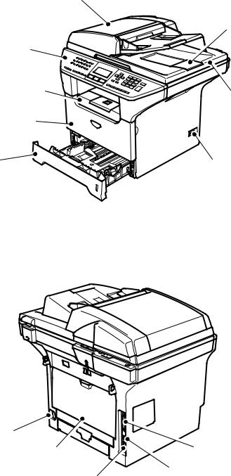
1.3 COMPONENTS
The equipment consists of the following major components:
ADF Unit
Panel Unit
Scanner Unit
NCU PCB
|
Speaker ASSY |
Joint Cover ASSY |
|
Driver PCB |
Laser Unit |
Outer Chute ASSY |
|
Back Cover |
Side Cover R |
Fuser Unit |
Frame Unit |
|
|
Main PCB |
|
|
Process Cover ASSY |
Front Cover
Access Cover |
PS PCB |
Side Cover L |
High-voltage PS PCB |
|
Paper Tray |
|
Fig. 1-6 |
1-7 |
Confidential |
CHAPTER 2
SPECIFICATIONS
Confidential
CHAPTER 2 SPECIFICATIONS
This chapter lists the specifications of each model, which enables you to make a comparison of different models.
|
|
|
CONTENTS |
|
2.1 |
GENERAL |
........................................................................................................................ |
2-1 |
|
|
2.1.1 |
General Specifications ......................................................................................... |
2-1 |
|
|
2.1.2 |
Paper Specifications............................................................................................. |
2-2 |
|
|
2.1.2.1 |
Paper handling ............................................................................................... |
2-2 |
|
|
2.1.2.2 |
Media specifications ....................................................................................... |
2-2 |
|
|
2.1.3 |
Printable Area ................................................................................................................ |
2-5 |
|
|
2.1.3.1 PCL5e/EPSON/IBM emulation....................................................................... |
2-5 |
||
|
2.1.3.2 |
PCLXL, PS (BR-Script 3)................................................................................ |
2-8 |
|
|
2.1.4 Print Speeds with Various Settings............................................................................. |
2-9 |
||
|
2.1.5 Toner Cartridge Weight Information ......................................................................... |
2-10 |
||
2.2 |
SPECIFICATIONS LIST................................................................................................. |
2-11 |
||
Confidential
2.1 |
GENERAL |
|
2.1.1 |
General Specifications |
|
|
Memory Capacity |
32 MB |
|
Automatic Document Feeder (ADF) |
Up to 50 sheets (Staggered) |
|
Paper Tray |
250 Sheets (20 lb (80 g/m 2 )) |
|
Printer Type |
Laser |
|
Print Method |
Electrophotography by semiconductor laser beam |
|
|
scanning |
|
Liquid Crystal Display (LCD) |
22 characters x 5 lines |
|
Power Source |
120V AC 50/60Hz (U.S.A./Canada) |
|
|
220 to 240V AC 50/60Hz (Europe/Asia/Oceania) |
|
Power Consumption |
Sleep: 17W (Average) (For the models with the NCU) |
|
|
: 15W (Average) (For the models with out NCU) |
|
|
Standby: 85W (Average) |
|
|
Peak: 1092W (U.S.A./Canada) |
|
|
1104W (Europe/Asia/Oceania) |
|
Dimensions (W x D x H) |
531 mm x 450 mm x 475 mm (20.9” x 17.7” x 18.7”) |
|
|
(with out carton) |
|
Weight |
Without Drum/Toner Unit: |
|
|
MFC-8460N: 16.5 kg (36.4 lb) |
|
|
MFC-8860DN/8870DW: 16.7 kg (36.81 lb) |
|
Noise |
Operating: 55 dB A or less (when ADF scanning) |
|
|
Standby: 30 dB A or less |
|
Temperature |
Operating: 10 to 32.5°C (50°F to 90.5°F) |
|
|
Storage: 0 to 40°C (32°F to 104°F) |
|
Humidity |
Operating: 20 to 80% (without condensation) |
|
|
Storage: 10 to 90% (without condensation) |
2-1 |
Confidential |
2.1.2 |
Paper Specifications |
|
|
|
|
|
|
||
2.1.2.1 |
Paper handling |
|
|
|
|
|
|
||
|
|
|
|
|
|
|
|
|
|
|
|
Paper Input* |
|
|
All models |
|
|
||
|
|
|
|
|
|
|
|
|
|
|
|
Multi-purpose tray |
|
50 sheets |
|
|
|||
|
|
|
|
|
|
|
|
|
|
|
|
Paper tray (Standard) |
|
250 sheets |
|
|
|||
|
|
Lower tray (Option) |
|
250 sheets |
|
|
|||
|
|
|
|
|
|
|
|
|
|
|
|
* Calculated with 80 g/m2 (21 lb) paper. |
|
|
|
|
|||
|
|
|
|
|
|
|
|
|
|
|
|
Paper Input* |
|
|
All models |
|
|
||
|
|
|
|
|
|
|
|
|
|
|
|
Face-down |
|
|
150 sheets |
|
|
||
|
|
* Calculated with 80 g/m2 (21 lb) paper. |
|
|
|
|
|||
|
|
|
|
|
|
|
|
|
|
|
|
Duplex |
|
MFC-8460N/DCP8060 |
|
MFC-8860DN/8870DW |
|||
|
|
|
|
DCP-8065DN |
|||||
|
|
|
|
|
|
|
|
||
|
|
|
|
|
|
|
|
|
|
|
|
Manual Duplex |
|
|
|
Yes |
|
|
|
|
|
Automatic Duplex |
|
N/A |
|
|
|
Yes |
|
|
|
|
|
|
|
|
|
|
|
2.1.2.2Media specifications
(1)Media types
The machine loads paper from the installed paper tray or the multi-purpose tray. The feedable media type and size are different depending on the paper tray installed. The names for the paper trays in the printer driver and this guides are as follows;
Paper tray |
Tray 1 |
|
|
Multi-purpose tray |
MP Tray |
|
|
Optional lower tray unit |
Tray 2 |
|
|
Duplex tray for automatic duplex printing |
DX |
(for MFC-8860DN/8870DW, DCP-8065DN) |
|
|
|
The table in the next page shows the feedable media of each paper tray described above.
2-2 |
Confidential |
|
|
|
|
|
|
Choose the media |
|
Tray 1/2 |
|
MP Tray |
|
DX |
type from the |
|
|
|
|
|
|
printer driver |
Plain paper |
|
|
|
|
Yes |
Plain paper |
75 g/m2 to 105 g/m2 |
Yes |
|
Yes |
|
||
(20 to 28 lbs.) |
|
|
|
|
|
|
Recycled paper |
Yes |
|
Yes |
|
Yes |
Recycled paper |
Bond paper |
2 Yes |
|
2 Yes |
|
|
|
Rough paper- |
2 |
2 |
|
|
||
60 g/m2 to 161 g/m2 |
60 g/m to 105 g/m |
60 g/m to 161 g/m |
N/A |
Bond paper |
||
(16 to 43 lbs.) |
(16 to 28 lbs.) |
|
(16 to 43 lbs.) |
|
|
|
|
|
|
|
|
|
|
|
|
|
|
|
|
|
Thin paper |
|
|
|
|
Yes |
Thin paper |
60 g/m2 to 75 g/m2 |
Yes |
|
Yes |
|
||
(16 to 20 lbs.) |
|
|
|
|
|
|
Thick paper |
|
|
|
|
N/A |
Thick Paper or |
105 g/m2 to 161 g/m2 |
N/A |
|
Yes |
|
||
(28 to 43 lbs.) |
|
|
|
|
|
Thicker Paper |
|
|
|
|
|
|
|
|
Yes |
|
Yes |
|
|
|
Transparency |
Up to 10 sheets |
|
Up to 10 sheets |
|
N/A |
Transparencies |
|
A4 or Letter ** |
|
A4 or Letter |
|
|
|
Labels |
N/A |
|
Yes |
|
N/A |
Thicker Paper |
|
A4 or Letter |
|
||||
|
|
|
|
|
|
|
|
|
|
|
|
|
Envelopes, |
Envelopes |
N/A |
|
Yes |
|
N/A |
Env. Thin, |
|
|
|
|
|
|
Env. Thick |
*Up to 10 sheets
**Not available for the optional Tray 2.
(2)Media size
Tray 1 (Standard) |
Tray 2 (Option) |
MP Tray |
DX |
|
|
|
|
A4, Letter, Legal*, |
A4, Letter, Legal*, |
Width: |
A4, Letter, Legal* |
B5 (ISO), Excutive, |
B5 (ISO), Excutive, |
69.9 to 215.9 mm |
|
A5, A6, B6 (ISO) |
A5, B6 (ISO) |
(2.75 to 8.5 in.) |
|
|
|
Length: |
|
|
|
116 to 406.4 mm |
|
|
|
(4.57 to 16 in.) |
|
*Legal size paper is not available in some regions outside the U.S.A. and Canada.
(3)Media weights
Tray 1 |
Tray 2 |
MP Tray |
DX |
|
Lower tray unit |
||
|
(Option) (LT-5300) |
|
|
60 to 105 g/m2 |
60 to 105 g/m2 |
60 to 161 g/m2 |
60 to 105 g/m2 |
(16 to 28 lb.) |
(16 to 28 lb.) |
(16 to 43 lb.) |
(16 to 28 lb.) |
|
2-3 |
|
Confidential |
Loading...