


Therm 4000 S
Bosch Therm 4000 S, GWH 12 CTDE 23 F5 S7805, GWH 12 CTDE 31 F5 S7805 Installation And Operating Instructions Manual
Installation and operating instructions
Balanced flue gas instantaneous water heater
Therm 4000 S
GWH 12 CTD E.. F5..
6 720 815 298 (2017/05) GB

2
Table of Contents
Therm 4000 S – 6 720 815 298 (2017/05)
Table of Contents
1 Key to symbols and safety instructions . . . . . . . . . . 3
1.1 Explanation of symbols . . . . . . . . . . . . . . . . . 3
1.2 General safety instructions . . . . . . . . . . . . . . 3
2 Product details . . . . . . . . . . . . . . . . . . . . . . . . . . . . . . . 5
2.1 Intended use . . . . . . . . . . . . . . . . . . . . . . . . . 6
2.2 EC declaration of type conformity . . . . . . . . 6
2.3 Type overview . . . . . . . . . . . . . . . . . . . . . . . . 6
2.4 Scope of delivery . . . . . . . . . . . . . . . . . . . . . . 6
2.5 Data plate . . . . . . . . . . . . . . . . . . . . . . . . . . . . 6
2.6 Description of the device . . . . . . . . . . . . . . . 6
2.7 Accessories (not included within the
scope of delivery) . . . . . . . . . . . . . . . . . . . . . .6
2.8 Dimensions and minimum clearances . . . . . 7
2.9 Layout of device . . . . . . . . . . . . . . . . . . . . . . 8
2.10 Wiring diagram . . . . . . . . . . . . . . . . . . . . . . . 9
2.11 Technical specifications . . . . . . . . . . . . . . . 10
2.12 Product data on energy consumption . . . . 11
2.13 Flue accessories . . . . . . . . . . . . . . . . . . . . . 12
2.13.1 Vertical flue gas routing . . . . . . . . . . . . . . . . 13
2.13.2 Horizontal flue gas routing . . . . . . . . . . . . . 13
3 Operating instructions . . . . . . . . . . . . . . . . . . . . . . . 14
3.1 Digital display - Description . . . . . . . . . . . . 14
3.2 Before commissioning the device . . . . . . . 14
3.3 Device ON/OFF . . . . . . . . . . . . . . . . . . . . . . 14
3.4 Setting the temperature . . . . . . . . . . . . . . . 14
3.5 Program key . . . . . . . . . . . . . . . . . . . . . . . . . 15
3.6 Draining the device . . . . . . . . . . . . . . . . . . . 15
3.7 Error codes on the display . . . . . . . . . . . . . 15
3.8 Cleaning the casing of the device . . . . . . . . 15
4 Regulations . . . . . . . . . . . . . . . . . . . . . . . . . . . . . . . . . 16
5 Installation (only for approved contractors) . . . . . 16
5.1 Important information . . . . . . . . . . . . . . . . . 16
5.2 Selecting the installation location . . . . . . . 17
5.2.1 Regulations for the installation location . . . 17
5.2.2 Total length of the flue system (Type C
devices) . . . . . . . . . . . . . . . . . . . . . . . . . . . 17
5.3 Minimum clearances . . . . . . . . . . . . . . . . . . 17
5.4 Fitting the wall mounting bracket . . . . . . . . 18
5.5 Installing the device . . . . . . . . . . . . . . . . . . 19
5.6 Water connection . . . . . . . . . . . . . . . . . . . . 19
5.7 Gas connection . . . . . . . . . . . . . . . . . . . . . . 20
5.8 Installation of the flue gas/air accessories . 20
5.9 Altitude of installation location . . . . . . . . . . 21
5.10 Starting the device . . . . . . . . . . . . . . . . . . . 21
6 Electrical connection (only for approved
contractors) . . . . . . . . . . . . . . . . . . . . . . . . . . . . . . . . .22
6.1 Power cable . . . . . . . . . . . . . . . . . . . . . . . . . 22
6.2 Replacing power cable . . . . . . . . . . . . . . . . 22
7 Gas regulating (only for approved contractors) . . 22
7.1 Factory setting . . . . . . . . . . . . . . . . . . . . . . 22
7.2 Service mode . . . . . . . . . . . . . . . . . . . . . . . 23
7.3 Gas supply with propane gas . . . . . . . . . . . 23
7.4 Setting the device . . . . . . . . . . . . . . . . . . . . 23
7.4.1 Access to the pressure test ports . . . . . . . . 23
7.4.2 Setting the maximum gas volume
(parameter P1) . . . . . . . . . . . . . . . . . . . . . . .23
7.4.3 Setting the minimum gas volume
(parameter P2) . . . . . . . . . . . . . . . . . . . . . . .24
7.4.4 Adjustment of the burner nozzle pressure
(parameter P0) . . . . . . . . . . . . . . . . . . . . . . .24
7.4.5 Factory setting (parameter P4) . . . . . . . . . 24
7.5 Converting gas type . . . . . . . . . . . . . . . . . . 25
8 Maintenance (only for approved contractors) . . . 25
8.1 Removing the casing . . . . . . . . . . . . . . . . . . 25
8.2 Regular maintenance . . . . . . . . . . . . . . . . . 25
8.3 Replacing the fuses (control device) . . . . . 26
8.4 Putting into operation after maintenance . 26
8.5 Safe operation/ risk for prolonged use . . . 26
9 Faults . . . . . . . . . . . . . . . . . . . . . . . . . . . . . . . . . . . . . . 27
10 Environmental protection/disposal . . . . . . . . . . . . 28
3
Key to symbols and safety instructions
Therm 4000 S – 6 720 815 298 (2017/05)
1 Key to symbols and safety instructions
1.1 Explanation of symbols
Warnings
The following signal words are defined and can be used in this
document:
• NOTICE indicates that material damage may occur.
• CAUTION indicates that minor to medium personal injury
may occur.
• WARNING indicates that severe or life-threatening
personal injury may occur.
• DANGER indicates that severe to life-threatening personal
injury will occur.
Important information
Additional symbols
1.2 General safety instructions
These installation instructions are
directed to the owner of the device as
well as to approved gas, water and
heating engineers and electricians.
▶ Read and retain the operating
instructions (device, heating
controller, etc.) prior to operation.
▶ Read the installation instructions
(device, heating controller, etc.) prior
to operation.
▶ Observe safety instructions and
warnings.
▶ Observe national and regional
regulations, technical rules and
guidelines.
▶ Keep a record of all work carried out.
If you smell gas
A gas leak could potentially cause an
explosion. Observe the following rules if
you smell gas.
▶ Avoid producing flames or sparks:
– Do not smoke, do not use a lighter
or strike matches.
– Do not operate any electrical
switches or pull out any plugs.
– Do not use the telephone or ring
doorbells.
▶ Turn off the gas supply at the main
shut-off valve or at the gas meter.
▶ Open windows and doors.
▶ Warn your neighbours and leave the
building.
▶ Prevent anyone from entering the
building.
▶ Stay well away from the building: call
the emergency services and the gas
supplier.
Intended use
The device may only be used for DHW
heating for domestic use or for similar
Warnings in the text are indicated by a
warning triangle.
In addition, signal words are used to indicate
the type and seriousness of the ensuing risk
if measures for minimising the danger are
not taken.
Important information where there is no
danger to people or property is indicated
with the adjacent symbol.
Symbol Meaning
▶Step
Cross-reference to another part of the document
• List/list entry
– List/list entry (second level)
Table 1

4
Key to symbols and safety instructions
Therm 4000 S – 6 720 815 298 (2017/05)
purposes, and it may only be operated
on an intermittent basis.
Any other type of use is considered as
improper. Any damage that may result is
excluded from liability.
Installation, commissioning and
maintenance
Installation, commissioning and
maintenance may only be carried out by
an approved contractor.
▶ Check all connections on the device
for leaks (gas, water and flue gas).
▶ In the case of open flue operation:
▶ Ensure that the installation location
meets the ventilation requirements.
▶ Only install original spare parts.
Inspection and maintenance
Regular inspection and maintenance are
prerequisites for safe and
environmentally compatible operation
of the heating system.
We recommend arranging an annual
inspection and maintenance contract
with the manufacturer.
▶ Have work carried out only by an
approved contractor.
▶ All defects that are detected must be
eliminated immediately.
Every situation, which does not
correspond to the conditions described
in the manual, must be evaluated by an
approved technician. If there is approval
for this, the contractor must specify a
catalogue of maintenance
requirements, which take wear and the
particular operating conditions into
account, and which comply with the
standards and requirements of the
country.
Conversion and repairs
Unprofessional modifications to the
device or other parts of the installation
can result in personal injury and/or
material damage.
▶ Have work carried out only by an
approved contractor.
▶ Never remove the panelling of the
device.
▶ Never carry out any modifications to
the device or to other parts of the
installation.
Electrical work
Electrical work may only be carried out
by qualified and approved electricians.
▶ Before starting electrical work:
– Isolate all poles of the mains
voltage and secure against
reconnection.
– Using suitable means, test that the
power supply is disconnected.
▶ Also observe the connection
diagrams of other system
components.
Open flue operation
The installation location must be
adequately ventilated, if the device
draws its combustion air from the room.
▶ Never cover or reduce the size of

5
Product details
Therm 4000 S – 6 720 815 298 (2017/05)
ventilation openings in doors,
windows and walls.
▶ Consult an approved contractor in the
following cases to ensure that the
ventilation requirements are met:
– If structural modifications are
made (e.g. replacing windows and
doors)
– If devices with an air discharge
outside are subsequently installed
(e.g. extractor or circulation fans,
kitchen fans or air conditioning
units).
Combustion air/ambient air
The air in the installation location must
be free of flammable or chemically
aggressive substances.
▶ Do not store or use any highly
flammable or explosive materials
(paper, petrol, thinners, paints etc.)
within the vicinity of the heat source.
▶ Do not store or use any corrosive
substances (solvents, adhesives,
chlorinated cleaning agents, etc.)
within the vicinity of the heat source.
Handover to the user
Instruct the user in the operation and
operating conditions of the product.
▶ Explain the operation - with particular
emphasis on all safety-related
actions.
▶ Explain that conversions or repairs
must only be carried out by an
approved contractor.
▶ Point out the need for regular
inspections and maintenance for safe
and environmentally compatible
operation.
▶ The installation and operating
instructions must be given to the user
for keeping.
Safety of electrical devices for
domestic use and similar purposes
The following requirements apply in
accordance with EN 60335-1 in order to
prevent hazards when using electrical
devices:
“This device may be operated by
children aged 8 or over, by people with
physical, sensory and mental
disabilities, and by people who have no
experience with this type of device,
provided they are supervised or
instructed on how to use the device
safely and on the associated risks.
Children must not play with the device.
Children must not clean or service the
device without supervision.”
“In order to prevent hazards, damaged
power cables must be replaced by the
manufacturer, the service department
or an approved contractor, who has
been authorised by the manufacturer.”
2 Product details
GWH devices are for DHW heating. They can be started up by simply pressing a key.
6
Product details
Therm 4000 S – 6 720 815 298 (2017/05)
2.1 Intended use
The device may only be used for DHW heating.
The device may only be installed in mobile homes.
Any other use is considered inappropriate. Any damage that
may result is excluded from liability.
2.2 EC declaration of type conformity
This device complies with the requirements of European
Directives 2009/142/EC, 2006/95/EC, 2004/108/EC and
the model described in the EC type-examination certificate.
The device is tested in accordance with EN 26.
2.3 Type overview
[GWH]Gas instantaneous water heater
[12] DHW output (l/min)
[CT] Thermostatically controlled
[D] Digital user interface
[E] Electrical ignition
[23] Device set for natural gas
[31] Device set for butane
[F5] Air box
[S...] Special number
Test gas details with code number and gas category in
accordance with EN 437:
2.4 Scope of delivery
• Balanced flue gas instantaneous water heater
•Fixing materials
• Documents about the device
• Water connection accessories
• Connection accessories
• Gas isolator
2.5 Data plate
The data plate is located on the outside at the bottom of the
device.
At the relevant location there is information about the
output, type approvals and serial number of the device.
2.6 Description of the device
• Device for wall-mounted installation, irrespective of
chimney and room size
• Multi-function display
• Device for operation with natural gas or LPG
• Electronic ignition
•Flow meter
• Temperature sensor for monitoring the water temperature
at the water inlet and outlet of the device.
• Safety equipment:
– Ionising electrode
–Thermal fuse
– Hot water temperature sensor
–Switch box
–Air temperature sensor
• Electrical connection: 230 V, 50 Hz.
2.7 Accessories (not included within the scope of
delivery)
•Gas conversion kits
• Flue accessories
• Frost protection accessories
• Remote control.
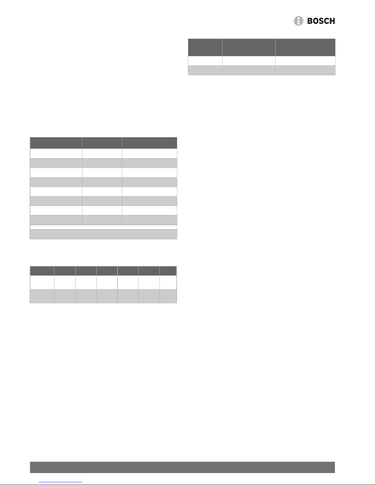
Type Country Category
GWH 12 PT, ES, IT, GB II
2R3R
NL II
2L3B/P (25; 30)
DE II
2ELL3B/P (20; 50)
FR II
2ESi3B/P (20/25; 30)
BE I
2E(S), I3B
AT-CH II
2H3B/P (20; 50)
HR II
2H3B/P (20; 30)
LU I
2E
Installation type B23, C13, C33, C43, C53, C
83
Table 2
GWH12 CT D E 23 F5 S....
GWH12 CT D E 31 F5 S....
Table 3
Code
numbers
Wobbe index
(W
S
) (15 °C)
Gas family
23 12.7-15.2 kWh/m
3
Natural gas group 2
31 20.2-21.3 kWh/m
3
LPG group 3
Table 4
7
Product details
Therm 4000 S – 6 720 815 298 (2017/05)
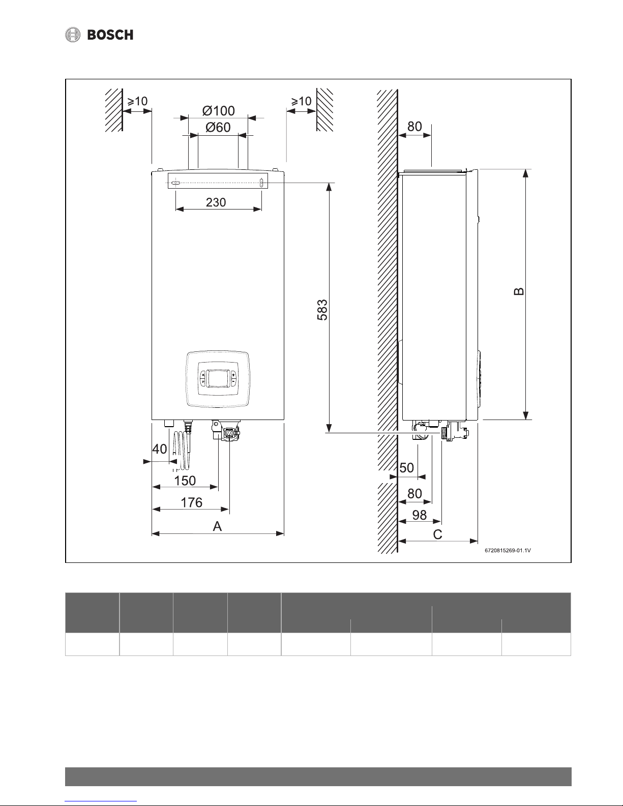
2.8 Dimensions and minimum clearances
Fig. 1 Dimensions (in mm)
Connection
Water Gas
A B C Cold water Domestic hot Natural gas LPG
GWH 12... 300 568 170 ¾ “ ½ “ ½ “ ½ “
Table 5 Dimensions (in mm)
8
Product details
Therm 4000 S – 6 720 815 298 (2017/05)
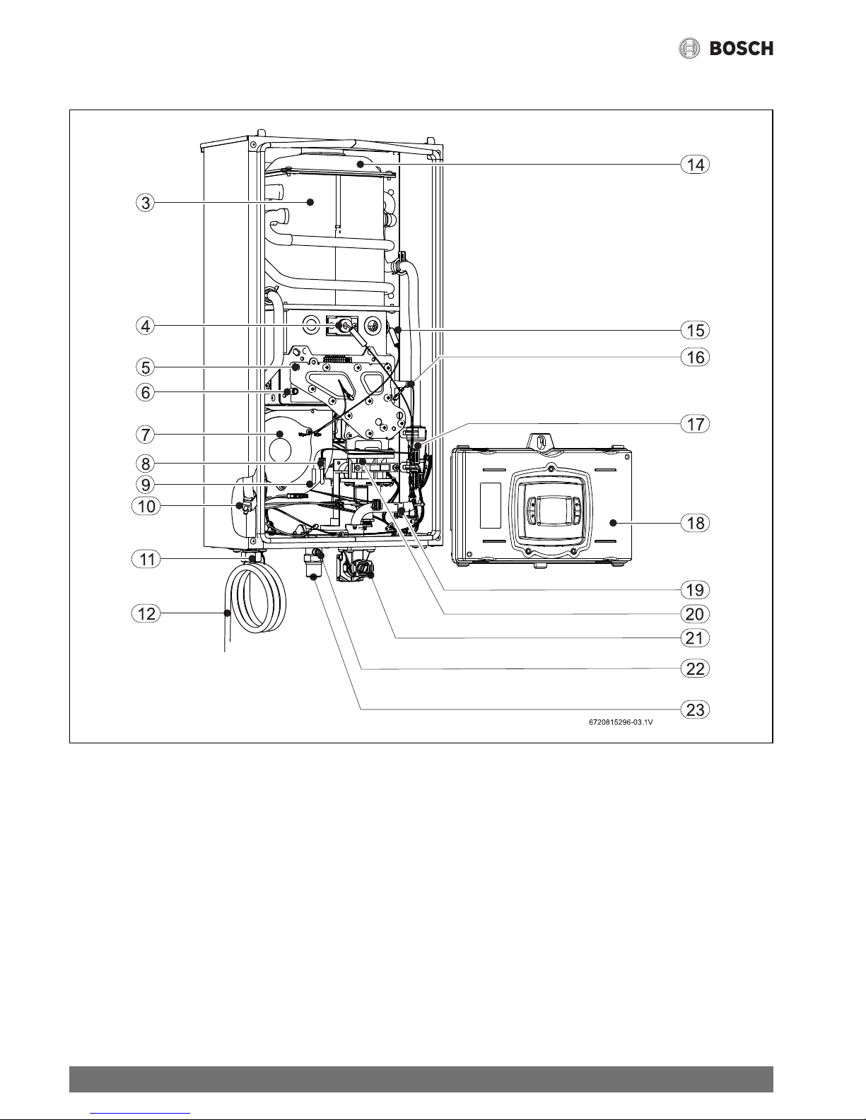
2.9 Layout of device
Fig. 2
[3] Combustion chamber
[4] Ionising electrode
[5] Burner
[6] Test port for air pressure in the casing
[7] Fan
[8] Air temperature sensor in the casing
[9] Thermal fuse
[10] Hot water temperature sensor
[11] DHW outlet
[12] Connecting lead with plug
[13] Combustion air test port
[14] Flue gas collector
[15] Ignition electrode
[16] Test port for gas pressure in the burner
[17] Flow meter
[18] Switch box
[19] Cold water temperature sensor
[20] Gas isolator
[21] Water inlet
[22] Test port for gas pressure at the gas connection
[23] Gas
9
Product details
Therm 4000 S – 6 720 815 298 (2017/05)
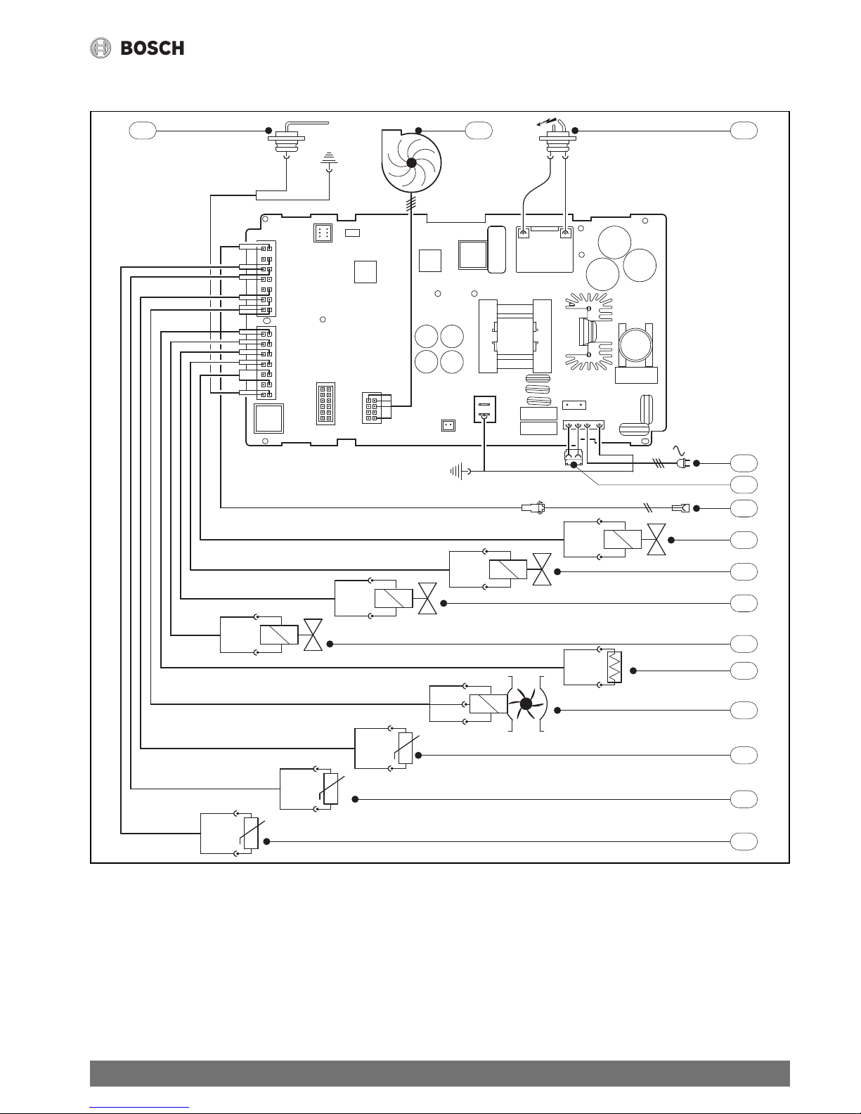
2.10 Wiring diagram
Fig. 3 Wiring diagram
[1] Ionising electrode
[2] Fan
[3] Ignition electrode
[4] Power supply
[5] Connection for frost protection accessories
[6] Connection for remote control
[7] Solenoid valve 1
[8] Solenoid valve 2
[9] Solenoid valve 3
[10] Solenoid valve 4
[11] Thermal fuse
[12] Flow meter
[13] Air temperature sensor in the casing
[14] Hot water temperature sensor
[15] Cold water temperature sensor
6720804089-10.1V
1 32
4
6
7
8
9
10
11
12
13
14
15
230 V
AC
M1
5
10
Product details
Therm 4000 S – 6 720 815 298 (2017/05)
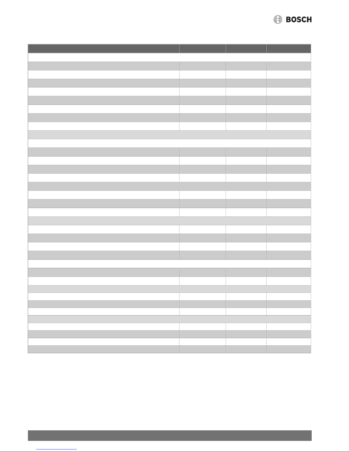
2.11 Technical specifications
Technical properties Symbols Unit GWH12
Output
1)
1) Hi 15- 1013 mbar - dry: Natural gas (G20) 34.02 MJ/m3 (9.5 kWh/m3) / Natural gas (G25) 37.38 MJ/m3 (10.38 kWh/m3)
Butan 45,65 MJ/kg (12,7 kWh/kg) - Propan 46,34 MJ/kg (12,9 kWh/kg) °C
Max. rated output (G20 / G31 / G25) Pn kW 20.8
Max. rated output (G25)
2)
2) G25: Category E(S), ESi
Pn kW 16.6
Minimum rated output (G20 / G31 / G25) Pmin kW 2.9
Minimum rated output (G25)
2)
Pmin kW 2.3
Heat load Qn kW 22.5
Minimum rated heat load Qmin kW 3.0
Efficiency at 100% of the rated heat load % 91.5
Efficiency at 30% of the rated heat load % 94
Gas specification
Permitted gas supply pressure
Natural gas G20 mbar 20
Natural gas G25 mbar 25
Butane G30 mbar 28-30 / 50
Propane G31 mbar 30 / 37 / 50
Gas supply value
Natural gas G20 m
3
/h 2.4
Butane G30 kg/h 1.8
Propane G31 kg/h 1.7
Water specification
Max. permitted pressure
3)
3) Allowing for water expansion, this value must not be exceeded.
pw bar 12
Minimum operating pressure pwmin bar 0.1
Switch-on flow rate l/min 2.2
Max. water volume at a l/min 9.0
Flue gas specification
Flow rate of the combustion products
4)
4) At rated heat output
kg/h 50
Flue gas temperature at the test points °C 170
Electrical specification
Power supply V 230
Max. power consumption W 100
IP rating IPX4D
General information
Weight (excl. packaging) kg 10
Height mm 570
Width mm 300
Depth mm 170
Table 6
11
Product details
Therm 4000 S – 6 720 815 298 (2017/05)
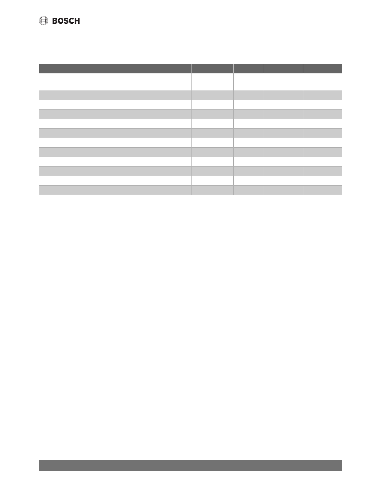
2.12 Product data on energy consumption
The following product data complies with the requirements of EU Regulations 811/2013, 812/2013, 813/2013 and 814/2013
as supplement to the Directive 2010/30/EU.
Product data Symbol Unit 7736503028 7736503029
Product type – – GWH 12 CTDE
23 F5 S7805
GWH 12 CTDE
31 F5 S7805
Emissions of nitrogen oxides NO
x
mg/kWh 127 127
Sound power level, indoors L
WA
dB(A) 67 67
Declared load profile – – M M
Water heating energy efficiency class – – A A
Water heating energy efficiency
wh
% 73 73
Annual electricity consumption AEC kWh 15 15
Daily electricity consumption (average climate conditions) Q
elec
kWh 0,068 0,068
Annual fuel consumption AFC GJ 6 6
Daily fuel consumption Q
fuel
kWh 8,439 8,439
Smart control enabled? – – No No
Thermostat temperature (factory setting) T
set
°C 60 60
Table 7 Product data on energy consumption
12
Product details
Therm 4000 S – 6 720 815 298 (2017/05)
2.13 Flue accessories
Condensate trap
We recommend the use of a condensate trap.
Fig. 4 Concentric pipes
[A] Running length of the flue
[B] Temperature of the suction air
Fig. 5 Separate pipes
[A] Running length of the flue
[B] Temperature of the suction air
DANGER: The flue must not have any leaks
after it has been installed.
▶ Should this requirement not be met, flue
gas could enter the installation room,
which could result in severe injury or
death.
See accessories list below. For the correct
operation of the device use only genuine
accessories.
(A)
10 m
9 m
7 m
6 m
8 m
5 m
4 m
3 m
2 m
1 m
0 m
0°C-5°C-10°C 5°C 10°C 15°C 20°C 25°C
(B)
6720809968-04.3V
0°C-5°C-10°C 5°C 10°C 15°C 20°C 25°C
(B)
6720809968-03.3V
(A)
0 m
2 m
4 m
1 m
3 m
6 m
5 m
9 m
7 m
8 m
10 m
15 m
11 m
14 m
12 m
13 m
13
Product details
Therm 4000 S – 6 720 815 298 (2017/05)
Concentric pipes
The concentric pipes of the flue accessories have an internal
diameter of 60 mm and an external diameter of 100 mm.
Separate pipes
The separate pipes of the flue accessories have an internal
diameter of 80 mm.
2.13.1 Vertical flue gas routing
Maximum lengths (Lmax)
2.13.2 Horizontal flue gas routing
Maximum lengths (Lmax)
Type Description Item number
AZ369 Set for vertical flue gas routing 7 716 050 044
AZ361 Set for horizontal telescopic connection (425-725 mm) 7 716 050 036
AZ362 Set for horizontal flue gas routing 7 716 050 037
--- 90° bend 7 736 995 079
--- 45° bend 7 736 995 071
--- Straight section 350 mm 7 736 995 059
--- Straight section 750 mm 7 736 995 063
--- Straight section 1500 mm 7 736 995 067
--- Condensate trap for horizontal flue gas routing 7 736 995 087
--- Condensate trap for vertical flue gas routing 7 736 995 089
Table 8 Flue accessories Ø 60-100 mm
Type Description Item number
----- Adaptor for concentric pipe (Ø 60/100 ->Ø 80-Ø 80) 7 736 995 095
----- 90° bend 7 736 995 107
----- 45° bend 7 736 995 106
----- Straight section 500 mm 7 736 995 100
----- Straight section 1000 mm 7 736 995 101
----- Straight section 2000 mm 7 736 995 102
----- Straight section 1000 mm + pipe bottoms 7 736 995 105
----- Straight section 135 mm with condensate collector 7 736 995 103
Table 9 Flue accessories Ø 80 mm
Lmax
Concentric pipes Separate pipes
GWH12 12 m 15 m + 15 m
Table 10
Lmax
Concentric pipes Separate pipes
GWH12 10 m 15 m + 15 m
Table 11

14
Operating instructions
Therm 4000 S – 6 720 815 298 (2017/05)
3 Operating instructions
3.1 Digital display - Description
Fig. 6 Digital display
[1] ON/OFF key
[2] Program key
[3] LCD display
[4] Forwards key
[5] Backwards key
3.2 Before commissioning the device
▶ It must be ensured that the gas type, which is given on the
data plate, corresponds to that which is available at the
installation location.
▶ Connect the device to the power supply.
▶ Open the gas isolator on the system.
▶ Open the water tap on the system.
3.3 Device ON/OFF
Switching on
▶ Press the key.
The display shows the desired DHW temperature.
Fig. 7
Switching off
▶ Press the key.
3.4 Setting the temperature
▶ Press the or keys, until the desired value is set.
Fig. 8
If the temperature is set to the lowest possible value in line with
the particular requirement, the energy and water consumption
Open all shut-off valves for gas and water.
CAUTION: Risk of burns!
The front can become very hot in the area of
the burner, and there is a risk of burns if it is
touched.
CAUTION:
▶The instantaneous water heater must be
commissioned for the first time by an
approved contractor, who should
provide the customer with all the
required information for proper
operation of the device.
The DHW temperature is set as standard to
42 °C.
The temperature shown on the display
corresponds to the preset temperature.
15
Operating instructions
Therm 4000 S – 6 720 815 298 (2017/05)
will be reduced, and it will be easier to prevent any possible
limescale deposits in the internal body of the device.
Water flow rate
The temperature, which is shown on the display, flashes until
the set value is reached.
If the set temperature is not reached after 30 seconds, the
symbol of a water tap appears on the display to show that the
water volume has to be matched correctly.
▶ Increase the water volume to reach the set
temperature.
▶ Reduce the water volume to reach the set
temperature.
3.5 Program key
Saving the DHW outlet temperature
Fig. 9
▶ Press the or keys to set the temperature that is
to be saved.
▶ Press the program key and hold it down for 3 seconds to
save the temperature.
The set temperature is saved, when the display no longer
flashes.
Selecting the saved temperature
To select the saved temperature:
▶ Hold the program key down for 1 second.
The display shows the previously saved temperature. This is
now the selected temperature.
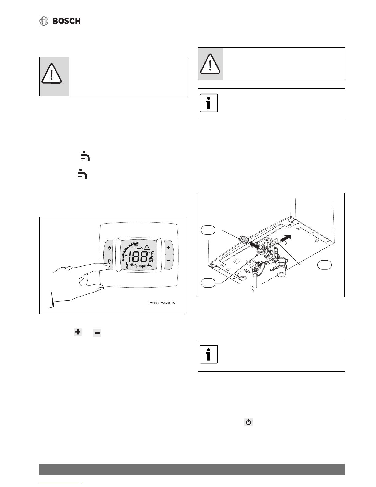
3.6 Draining the device
If there is a danger of frost:
▶ Close the water shut-off valve, which is upstream of the
device.
▶ Open one hot water tap.
▶ Remove the fixing ring [2] from the cold water pipe [1].
▶ Remove the holder [3].
▶ Allow the water inside the device to flow out completely.
Fig. 10 Drain screw
[1] Water inlet
[2] Fixing ring
[3] Cap
3.7 Error codes on the display
See Tab. 18 on page 27.
Resetting the device
Many faults can be eliminated by resetting the device:
▶ Hold down the key for 3 seconds.
3.8 Cleaning the casing of the device
▶ If required, clean the casing with a damp cloth.
CAUTION: The temperature indicator on the
display shows an approximate value. Always
test the temperature with your hand before
bathing.
NOTICE:
Frost can result in damage to the device: drain
the device if there is a danger of frost.
Place a container under the device to
completely catch the water flowing out.
Installing a frost protection accessory protects
the device from freezing.
6720804089-07.1V
3
1.
2.
2
1
16
Regulations
Therm 4000 S – 6 720 815 298 (2017/05)
4Regulations
The currently applicable European standards must be
observed. Installation, repairs and maintenance must only be
carried out by approved contractors.
The appliance installation must meet the requirements of
EN1949 standard.
5 Installation (only for approved
contractors)
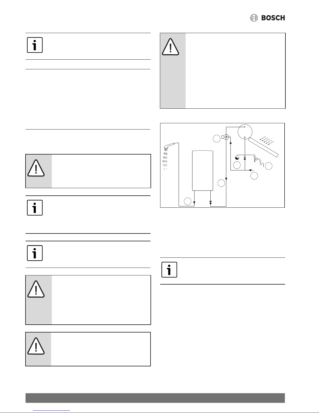
Solar system (thermosiphon)
Fig. 11 Solar system
[1] Cold water
[2] Water inlet
[3] Thermostatic valve
[4] Expansion vessel
[5] Safety assembly
5.1 Important information
▶ Prior to installation, consult your gas supplier about wall-
mounted gas boilers and ventilation at the installation
location, and also observe all the relevant standards.
Water quality
The device is used for DHW heating for domestic purposes in
accordance with the relevant regulations. Use of a water
treatment system is recommended in areas with a high level of
water hardness. The water parameters, which have an effect on
limescale, must generally comply with the values given in
Tab. 12.
Never use aggressive or corrosive cleaning
agents.
DANGER: Risk of explosion!
▶ Always close the gas isolator prior to
commencing any work on gas-carrying
components.
The installation, electrical connection, gas
connection and the connection of the air
suction and flue pipes, as well as the initial
commissioning, must only be carried out by
approved contractors.
The device may only be used in the countries
that are given on the data plate.
NOTICE: Damage to the device!
Leaking connections.
▶ Do not put the device down on the floor
with the connections facing
downwards, so that the metal threads
are not damaged.
NOTICE: Appliance malfunction!
▶ Always place the appliance front cover
after installation or after maintenance
work.
CAUTION:
▶ The water inlet temperature for the
device must not exceed 60 °C.
▶ If the water inlet temperature reaches
higher values, a 3-way valve or a
thermostatic valve (set for values below
60 °C) must be fitted upstream of the
device.
▶ In the case of solar systems, ensure that
the system has an expansion vessel.
In the case of water outlet temperatures
above 45 °C, the use of a decalcification
system is recommended.
2
2
1
3
6720608999-11.6V
T
5
4
17
Installation (only for approved contractors)
Therm 4000 S – 6 720 815 298 (2017/05)
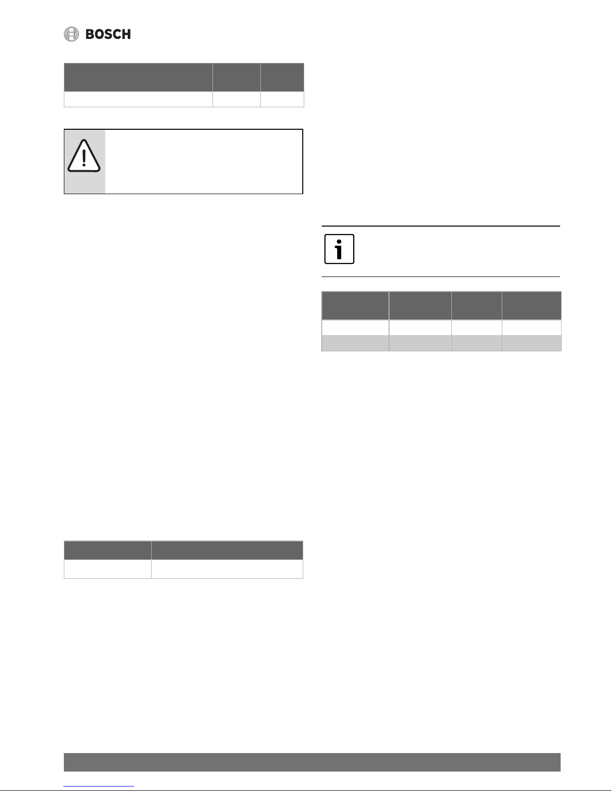
5.2 Selecting the installation location
5.2.1 Regulations for the installation location
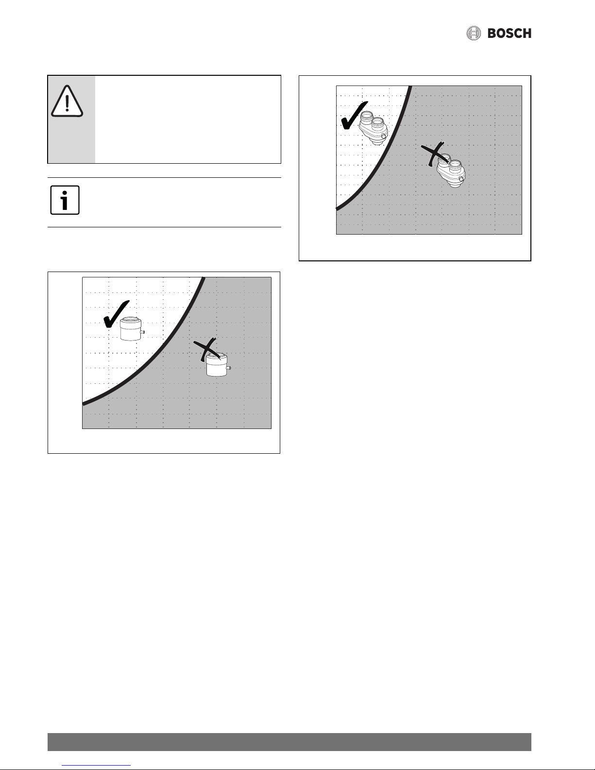
General notes
▶ Observe country-specific requirements.
▶ Never install the instantaneous water heater above a heat
source.
▶ Maintain the minimum clearances specified in Fig. 12.
▶ Never install the device in rooms, where the temperature
can fall below freezing point (0 °C). When there is a danger
of frost, switch the device OFF and drain it ( Fig. 10).
-or-
▶ Installing frost protection accessories.
▶ It must be ensured that at the installation location there is a
socket available, which is easily accessible after the
instantaneous water heater has been installed.
Type B devices
▶ Only install the device in rooms with a minimum size of
8m
3
. The furniture should not comprise more than 2 m3.
Air supply (Type B devices)
Depending on the type of device, the location intended for the
installation of the device must have the area for air supply that
is listed in the table.
In addition to the above minimum requirements, countryspecific requirements must also be observed.
Combustion air
The air grille for the air suction must be located in a well
ventilated room.
Keep the supply of combustion air free of corrosive substances
to prevent corrosion.
Corrosive substances include halogenated hydrocarbons
which contain chlorine and fluoride compounds. These could
be contained in, for example, solvents, paints, adhesives,
propellants and domestic cleaning agents.
If these conditions cannot be met, another location must be
selected for the air supply.
5.2.2 Total length of the flue system (Type C devices)
The total length of the flue system must not exceed the values
given in Tabs. 10 and 11, and it must not be smaller than the
values (Lmin) given in Tab. 14.
The equivalent length (Leq) must be taken into account for
each accessory used, when determining the overall length of
the system.
Surface temperature
The maximum surface temperature of the device is less than
85 °C. In accordance with TRGI or TRF, it is not therefore
necessary to observe safety clearances for combustible
construction materials and installed furniture. Country-specific
guidelines must be observed.
5.3 Minimum clearances
When selecting the installation location for the device, the
following restrictions must be observed:
▶ Maximum clearance for all protruding parts, such as hoses,
pipes etc.
▶ Ensure easy accessibility for maintenance and observe the
minimum clearances shown in Fig. 12.
TDS (Total dissolved solids) (mg/l) Hardness
(mg/l)
PH
0 - 600 0 - 180 6.5 - 9.0
Table 12
NOTICE: Damage to the device!
If these values are not observed, it can result in
partial blockage and faster ageing of the
internal body of the device.
Device Minimum effective area
GWH12... 60 cm
2
Table 13 Effective area for the air supply
If the flue gas routing is horizontal, the first
bend after the outlet from the device must
not be taken into account for the calculation.
Ø Accessory
part
Leq Lmin
Ø 80 90 ° bend 1.5 m 0.5 m
Ø 60/100 90 ° bend 2m 0.375 m
Table 14 Equivalent lengths
18
Installation (only for approved contractors)
Therm 4000 S – 6 720 815 298 (2017/05)
Fig. 12 Minimum clearances
[A] At the side 1cm
[B] 40 cm
[C] At the front 2cm
Minimum clearances for the flues
Fig. 13 Minimum clearances for the flues
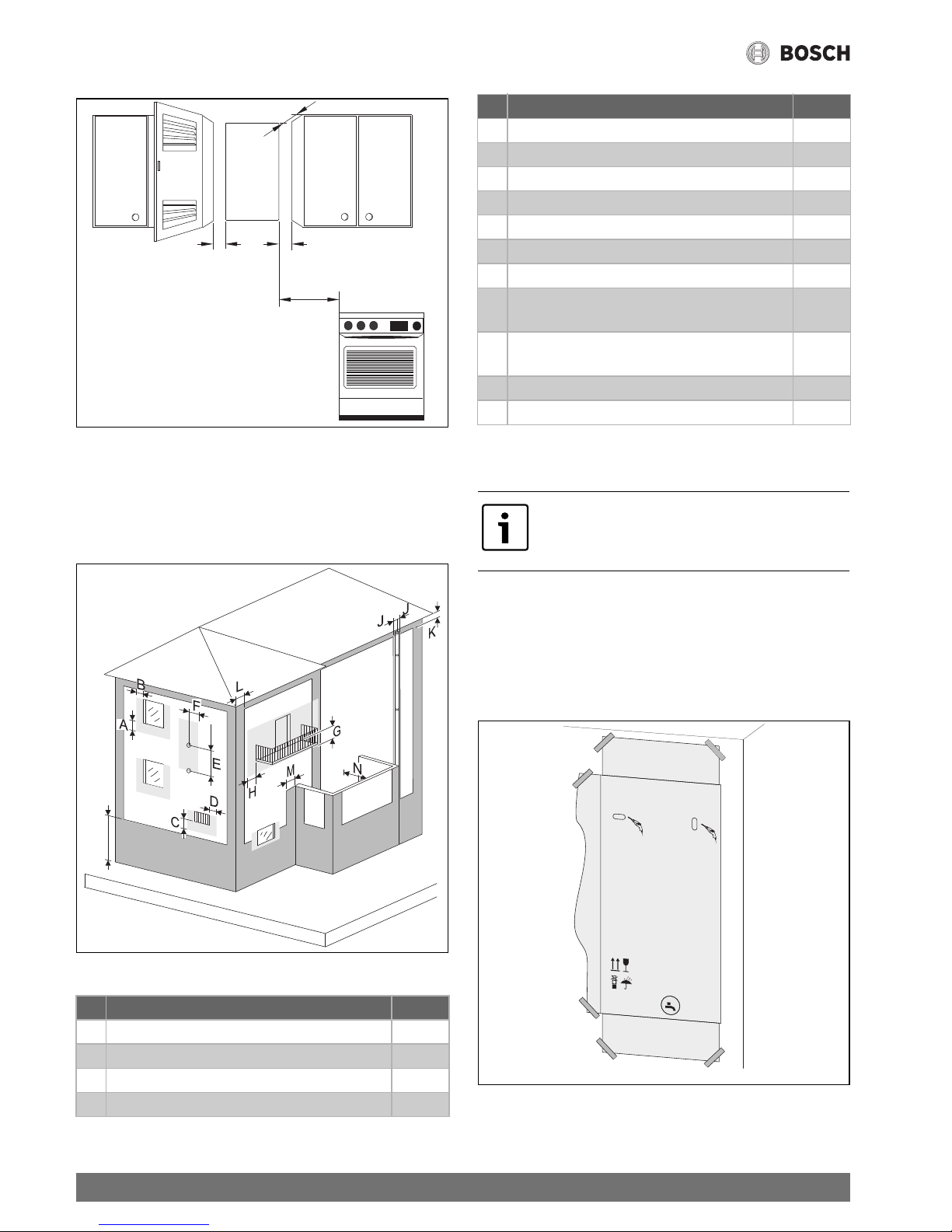
5.4 Fitting the wall mounting bracket
No special wall protection is required. The wall must be even
and with sufficient load-bearing capacity to hold the weight of
the device.
▶ Remove the device from the packaging.
▶ Fasten the packaging to the wall to mark the position of the
holes.
Fig. 14 Mounting template
▶ Remove the mounting template from the wall.
Minimum clearances for the flues (mm)
A Below a window 600
B Beside a window 400
C Below an air inlet or outlet opening 600
D Beside an air inlet or outlet opening 600
Table 15
C
AA
B
6720804089-14.1V
I
6720806426-05.2V
E Vertical clearance between two flues 1 500
F Horizontal clearance between two flues 600
G Below a balcony 300
H Beside a balcony 1 000
I To the floor or another floor of the building 2 200
J To vertically or horizontally running flues 300
K Below the roof edge 300
L To the wall / internal corner / external corner in
the case of buildings without windows
300
M To the wall / internal corner / external corner in
the case of buildings with windows
1 000
N To the front wall with windows 3 000
N To the front wall without windows 2 000
Prior to fitting the wall mounting bracket,
check whether the connections for water,
gas and flue accessories are available.
Minimum clearances for the flues (mm)
Table 15
Ø8mmØ
8
mm
Ø8mmØ
8
mm
_
_
_
_
_
_
_
_
_
_
_
_
_
_
_
_
_
_
_
_
_
_
_
_
_
_
_
_
_
_
_
_
_
_
_
_
_
_
_
_
_
_
_
_
_
_
_
_
_
_
_
_
_
_
_
_
_
_
_
_
_
_
_
_
_
_
_
_
_
_
_
_
_
_
_
_
_
_
_
_
_
_
_
_
_
_
_
_
_
_
_
_
_
_
_
_
_
_
_
_
_
_
_
_
_
_
_
_
_
_
_
_
_
_
_
_
_
_
_
_
_
_
_
_
_
_
c
s
lt
l
v
p
l
e
n
d
z
e
s
n
l
m
a
p
t
d
e
f
r
i
t
_
_
_
_
_
_
_
_
_
_
_
_
_
_
_
_
_
_
_
_
_
_
_
_
_
_
_
_
_
_
_
_
_
_
_
_
_
_
_
_
_
_
_
_
_
_
_
_
_
_
_
_
_
_
_
_
_
_
_
_
_
_
_
_
_
_
_
_
_
_
_
_
_
_
_
_
_
_
_
_
_
_
_
_
_
_
_
_
_
_
_
_
_
_
_
_
_
_
_
_
_
_
_
_
_
_
_
_
_
_
_
_
_
_
_
_
_
_
_
_
_
_
_
_
_
_
_
_
_
_
_
_
_
_
_
_
_
_
_
_
_
_
_
_
_
_
_
_
_
_
_
_
_
_
_
_
_
_
_
_
_
_
_
_
_
_
_
_
_
_
_
_
_
_
_
_
_
_
_
_
_
_
_
_
_
_
_
_
_
_
_
_
_
_
_
_
_
_
_
_
_
_
_
_
_
_
_
_
_
_
_
_
_
_
_
_
_
_
_
_
_
_
_
_
_
_
_
_
_
_
_
_
_
_
_
_
_
_
_
_
_
_
_
_
_
_
_
_
_
_
_
_
_
_
_
_
_
_
_
_
_
_
_
_
_
_
_
_
_
_
_
_
_
_
_
_
_
_
_
_
_
_
_
_
_
_
_
_
_
_
_
_
_
_
_
_
_
_
_
_
_
_
_
_
_
_
_
_
_
_
_
_
_
_
_
_
_
_
_
_
_
_
_
_
_
_
_
_
_
_
_
_
_
_
_
_
_
_
_
_
_
_
_
_
_
_
_
_
_
_
_
_
_
_
_
_
_
_
_
_
_
_
_
_
_
_
_
_
_
_
_
_
_
_
_
_
_
_
_
_
_
_
_
_
_
_
_
_
_
_
_
_
_
_
_
_
_
_
_
_
_
_
_
_
_
_
_
_
_
_
_
_
_
_
_
_
_
_
_
_
_
_
_
_
_
_
_
_
_
_
_
_
_
_
_
_
_
_
_
_
_
_
_
_
_
_
_
_
_
_
_
_
_
_
_
_
_
_
_
_
_
_
_
_
_
_
_
_
_
_
_
_
_
_
_
_
_
_
_
_
_
_
_
_
_
_
_
_
_
_
_
_
_
_
_
_
_
_
_
_
_
_
_
_
_
_
_
_
_
_
_
_
_
_
_
_
_
_
_
_
_
_
_
_
_
_
_
_
_
_
_
_
_
_
_
_
_
_
_
_
_
_
_
_
_
_
_
_
_
_
_
_
_
_
_
_
_
_
_
_
_
_
_
_
_
_
_
_
_
_
_
_
_
_
_
_
_
_
_
_
_
_
_
_
_
_
_
_
_
_
_
_
_
_
_
_
_
_
_
_
_
_
_
_
_
_
_
_
_
_
_
_
_
_
_
_
_
_
_
_
_
_
_
_
_
_
_
_
_
_
_
_
_
_
_
_
_
_
_
_
_
_
_
_
_
_
_
_
_
_
_
_
_
_
_
_
_
_
_
_
_
_
_
_
_
_
_
_
_
_
_
_
_
_
_
_
_
_
_
_
_
_
_
_
_
_
_
_
_
_
_
_
_
_
_
_
_
_
_
_
_
_
_
_
_
_
_
_
_
_
_
_
_
_
_
_
_
_
_
_
_
_
_
_
_
_
_
_
_
_
_
_
_
_
_
_
_
_
_
_
_
_
_
_
_
_
_
_
_
_
_
_
_
_
_
_
_
_
_
_
_
_
_
_
_
_
_
_
_
_
_
_
_
_
_
_
_
_
_
_
_
_
_
_
_
_
_
_
_
_
_
_
_
_
_
_
_
_
_
_
_
_
_
_
_
_
_
_
_
_
_
_
_
_
_
_
_
_
_
_
_
_
_
_
_
_
_
_
_
_
_
_
_
_
_
_
_
_
_
_
_
_
_
_
_
_
_
_
_
_
_
_
_
_
_
_
_
_
_
_
_
_
_
_
_
_
_
_
_
_
_
_
_
_
_
_
_
_
_
_
_
_
_
_
_
_
_
_
_
_
_
_
_
_
_
_
_
_
_
_
_
_
_
_
_
_
_
_
_
_
_
_
_
_
_
_
_
_
_
_
_
_
_
_
_
_
_
_
_
_
_
_
_
_
_
_
_
_
_
_
_
_
_
_
_
_
_
_
_
_
_
_
_
_
_
_
_
_
_
_
_
_
_
_
_
_
_
_
_
_
_
_
_
_
_
_
_
_
_
_
_
_
_
_
_
_
_
_
_
_
_
_
_
_
_
_
_
_
_
_
_
_
_
_
_
_
_
_
_
_
_
_
_
_
_
_
_
_
_
_
_
_
_
_
_
_
_
_
_
_
_
_
_
_
_
_
_
_
_
_
_
_
_
_
_
_
_
_
_
_
_
_
_
_
_
_
_
_
_
_
_
_
_
_
_
_
_
_
_
_
_
_
_
_
_
_
_
_
_
_
_
_
_
_
_
_
_
_
_
_
_
_
_
_
_
_
_
_
_
_
_
_
_
_
_
_
_
_
_
_
_
_
_
_
_
_
_
_
_
_
_
_
_
_
_
_
_
_
_
_
_
_
_
_
_
_
_
_
_
_
_
_
_
_
_
_
_
_
_
_
_
_
_
_
_
_
_
_
_
_
_
_
_
_
_
_
_
_
_
_
_
_
_
_
_
_
_
_
_
_
_
_
_
_
_
_
_
_
_
_
_
_
_
_
_
_
_
_
_
_
_
_
_
_
_
_
_
_
_
_
_
_
_
_
_
_
_
_
_
_
_
_
_
_
_
_
_
_
_
_
_
_
_
_
_
_
_
_
_
_
_
_
_
_
_
_
_
_
_
_
_
_
_
_
_
_
_
_
_
_
_
_
_
_
_
_
_
_
_
_
_
_
_
_
_
_
_
_
_
_
_
_
_
_
_
_
_
_
_
_
_
_
_
_
_
_
_
_
_
_
_
_
_
_
_
_
_
_
_
_
_
_
_
_
_
_
_
_
_
_
_
_
_
_
_
_
_
_
_
_
_
_
_
_
_
_
_
_
_
_
_
_
_
_
_
_
_
_
_
_
_
_
_
_
_
_
_
_
_
_
_
_
_
_
_
_
_
_
_
_
_
_
_
_
_
_
_
_
_
_
_
_
_
_
_
_
_
_
_
_
_
_
_
_
_
_
_
_
_
_
_
_
_
_
_
_
_
_
_
_
_
_
_
_
_
_
_
_
_
_
_
_
_
_
_
_
_
_
_
_
_
_
_
_
_
_
_
_
_
_
_
_
_
_
_
_
_
_
_
_
_
_
_
_
_
_
_
_
_
_
_
_
_
_
_
_
_
_
_
_
_
_
_
_
_
_
_
_
_
_
_
_
_
_
_
_
_
_
_
_
_
_
_
_
_
_
_
_
_
_
_
_
_
_
_
_
_
_
_
_
_
_
_
_
_
_
_
_
_
_
_
_
_
_
_
_
_
_
_
_
_
_
_
_
_
_
_
_
_
_
_
_
_
_
_
_
_
_
_
_
_
_
_
_
_
_
_
_
_
_
_
_
_
_
_
_
_
_
_
_
_
_
_
_
_
_
_
_
_
_
_
_
_
_
_
_
_
_
_
_
_
_
_
_
_
_
_
_
_
_
_
_
_
_
_
_
_
_
_
_
_
_
_
_
_
_
_
_
_
_
_
_
_
_
_
_
_
_
_
_
_
_
_
_
_
_
_
_
_
_
_
_
_
_
_
_
_
_
_
_
_
_
_
_
_
_
_
_
_
_
_
_
_
_
_
_
_
_
_
_
_
_
_
_
_
_
_
_
_
_
_
_
_
_
_
_
_
_
_
_
_
_
_
_
_
_
_
_
_
_
_
_
_
_
_
_
_
_
_
_
_
_
_
_
_
_
_
_
_
_
_
_
_
_
_
_
_
_
_
_
_
_
_
_
_
_
_
_
_
_
_
_
_
_
_
_
_
_
_
_
_
_
_
_
_
_
_
_
_
_
_
_
_
_
_
_
_
_
_
_
_
_
_
_
_
_
_
_
_
_
_
_
_
_
_
_
_
_
_
_
_
_
Pe
d
in
s
t
a
la
c
řč
řš
ě
ňš
ě
ř
šm
o
n
t
u
o
ja
n
t
p
e
rs
k
a
it
y
ti
m
o
n
ta
v
im
o
in
s
tr
u
k
c
i
j
ą!
šžp
e
r
s
k
a
ity
t
i
im
o
in
s
t
r
u
k
c
ij
ą!
žąą
ā
ž
a
s
iz
la
s
īt ža
s
ža s
iz
la
s
š
ādī
š
a
n
a
s
t
e
lp
a
i
j
ān
o
d
r
o
šin
a
v
ēd
in
ā
š
a
n
a
s
p
r
a
s
īb
a
s
!
ćę
ćęł
żłć ą
í
p
ro
s
tu
d
u
jte
in
s
ta
la
n
í
n
á
v
o
d
!
Pe
d
s
p
u
tn
í
m
p
r
o
s
tu
d
u
jt
e
n
á
v
o
d
p
r
o
o
b
s
lu
h
u
!
M
ís
tn
o
s
t
in
s
t
a
la
c
e
m
u
s
í
s
p
l
o
v
a
t
p
o
d
m
ín
k
y
p
r
o
z
a
ji
tn
í
p
ív
o
d
u
s
p
a
lo
v
a
n
é
h
o
v
z
d
u
c
h
u
!
P
r
ie
P
r
ie
p
a
le
id
ia
n
t
n
a
u
d
o
j
P
a
ta
lp
o
je
,
k
u
r
io
je
d
irb
s
r
e
n
g
in
y
s
,
u
tik
r
in
t
i
r
e
ik
ia
m
v
e
n
t
ilia
c
ij
!
P
ir
m
s
m
o
n
t
m
o
n
t
in
s
t
r
u
k
c
iju
!
li
e
to
a
n
a
s
in
s
t
r
u
k
c
iju
!
U
z
s
t
Vo
o
r
h
e
t
in
s
ta
lle
re
n
,
in
s
ta
lla
t
ie
v
o
o
r
s
c
h
r
if
t
d
o
o
r
le
z
e
n
!
Vo
o
r
h
e
t
in
b
e
d
r
ijft
n
e
m
e
n
,
b
e
d
ie
n
in
g
s
v
o
o
r
s
c
h
r
ift
d
o
o
rle
z
e
n
!
D
e
o
p
s
t
e
llin
g
s
r
u
im
t
e
d
ie
n
t
a
a
n
d
e
d
a
a
v
o
o
r
g
e
ld
e
n
d
e
v
o
o
r
s
c
h
rif
te
n
t
e
v
o
ld
o
e
n
!
P
r
z
e
d
z
a
in
s
t
a
lo
w
a
n
ie
m
p
r
z
e
c
z
y
ta
in
s
t
r
u
k
c
j
in
s
ta
la
c
ji!
P
rz
e
d
u
ru
c
h
o
m
ie
n
ie
m
p
r
z
e
c
z
y
ta
in
s
tr
u
k
c
j
o
b
s
u
g
i!
M
ie
js
c
e
m
o
n
t
a
u
m
u
s
i
s
p
e
n
ia
w
y
m
a
g
a
n
ia
d
o
t
y
c
z
c
e
w
e
n
ty
la
c
ji!
į
ā
āīt
R
e
a
d
in
s
ta
lla
t
io
n
m
a
n
u
a
l
p
r
io
r
to
in
s
ta
lla
tio
n
o
f
th
is
u
n
it
!
R
e
a
d
u
s
e
r
m
a
n
u
a
l
b
e
fo
r
e
p
u
tt
in
g
th
is
u
n
it
in
o
p
e
r
a
tio
n
!
T
h
e
in
s
ta
lla
t
io
n
ro
o
m
m
u
s
t
fu
lf
ill
th
e
v
e
n
tila
tio
n
r
e
q
u
ir
e
m
e
n
ts
!
L
e
e
r
la
s
in
s
tr
u
c
c
io
n
e
s
te
c
n
ic
a
s
a
n
t
e
s
d
e
in
s
t
a
la
r
e
l
a
p
a
r
a
to
!
L
e
e
r
la
s
in
s
t
r
u
c
c
io
n
e
s
p
a
r
a
e
l
u
s
u
a
r
io
a
n
t
e
s
d
e
p
o
n
e
r
e
n
f
u
n
c
io
n
a
m
ie
n
t
o
e
l
a
p
a
r
a
to
!
E
l
c
a
le
n
ta
d
o
r
s
o
lo
p
u
e
d
e
s
e
r
in
s
t
a
la
d
o
e
n
u
n
lo
c
a
l
q
u
e
c
u
m
p
la
lo
s
r
e
q
u
is
ito
s
d
e
v
e
n
t
ila
c
io
n
a
d
e
c
u
a
d
o
s
!
P
ir
m
s
ie
d
a
r
b
in
n
a
L
e
r
a
s
in
s
t
r
u
ç
õ
e
s
d
e
in
s
ta
la
ç
ã
o
a
n
t
e
s
d
e
in
s
t
a
la
r
o
a
p
a
r
e
lh
o
!
A
n
te
s
d
e
c
o
lo
c
a
r
o
a
p
a
r
e
lh
o
e
m
f
u
n
c
io
n
a
m
e
n
to
,
le
r
a
s
in
s
tr
u
ç
õ
e
s
d
e
u
tiliz
a
ç
ã
o
!
O
lo
c
a
l
d
e
in
s
t
a
la
ç
ã
o
d
e
v
e
c
u
m
p
r
ir
a
s
e
x
ig
ê
n
c
ia
s
d
e
v
e
n
t
ila
ç
ã
o
!
Vo
r
In
s
ta
lla
tio
n
In
s
ta
lla
t
io
n
s
a
n
le
it
u
n
g
le
s
e
n
!
Vo
r
I
n
b
e
t
r
ie
b
n
a
h
m
e
B
e
d
ie
n
u
n
g
s
a
n
le
itu
n
g
le
s
e
n
!
D
e
r
A
u
fs
t
e
llr
a
u
m
m
u
s
s
d
ie
B
e
lu
ftu
n
g
s
a
n
fo
r
d
e
ru
n
g
e
n
e
rfu
lle
n
!
L
ir
e
la
n
o
t
ic
e
t
e
c
h
n
iq
u
e
a
v
a
n
t
d
'in
s
ta
lle
r
l
'a
p
p
a
r
e
il!
L
ir
e
la
n
o
t
ic
e
d
'u
til
is
a
tio
n
a
v
a
n
t
la
m
is
e
e
n
fo
n
c
tio
n
n
e
m
e
n
t
d
e
l
'a
p
p
a
r
e
il!
L
e
lie
u
d
'in
s
ta
lla
tio
n
d
o
it
r
e
p
o
n
d
r
e
a
u
x
p
r
e
s
c
r
ip
t
io
n
s
d
e
v
e
n
tila
t!
P
r
im
a
d
i
e
f
fe
tt
u
a
re
l
'in
s
ta
lla
z
io
n
e
d
e
ll
'a
p
p
a
r
e
c
c
h
io
le
g
g
e
r
e
le
is
t
r
u
z
io
n
i
d
i
in
s
t
a
lla
z
io
n
e
!
P
rim
a
d
i
e
f
f
e
tt
u
a
r
e
la
m
e
s
s
a
in
s
e
r
v
iz
io
le
g
g
e
re
le
is
tr
u
z
io
n
i
d
'u
s
o
!
L
e
c
a
r
a
t
te
r
is
t
ic
h
e
d
i
v
e
n
til
a
z
io
n
e
d
e
l
lo
c
a
le
n
e
l
q
u
a
le
e
in
s
t
a
lla
t
o
l
'a
p
p
a
r
e
c
c
h
io
d
e
v
o
n
o
e
s
s
e
r
e
c
o
n
f
o
r
m
i
a
lle
n
o
r
m
a
tiv
e
v
ig
e
n
ti!
ز
ﺎﻬ
ﺟ
ﻟ
ﻛ
ﺗ
ﺑﻗ
ﺗﻛ
ﻟ
ﻗ
ﺟ
ز
ﺎﻬ
ﺟ
ﻟ
ﻐ
ﺷ
ﺗ
ﺑﻗ
ﺎﻣ
ﻌ
ﺗﺳ
ﻻ
ﺔ
ﻔ
ﻛ
ﻗ
ﺟ
ز
ﺔ
ﻬ
ﺗﻟ
ﺷ
ﻟ
ﺟ
ﺗﺳ
ﺟ
ز
ﺎﻬ
ﺟ
ﻟ
ﻛ
ﺗ
ﺎﻛ
ﻣ
ﺔ
ﻟﻵ
ﻛ
ﺗ
ﺑﻗ
ﻗ
ﻘ
ﺗﻟ
ت
ﺎﻣ
ﻠﻌ
ﺗﻟ
ﻗ
ﻰ
ﺟ
ﺔ
ﺔ
ﻟﻵ
ﻐ
ﺷ
ﺗ
ﺑﻗ
ﺎﻣ
ﻌ
ﺗ
ﺳ
ﻻ
ت
ﺎﻣ
ﻠﻌ
ﺗ
ﻗ
ﻰ
ﺟ
ﻟﺔ
ﻛ
ﺗﻟ
ﺎﻛ
ﻣ
ﻲ
ﻓ
ﺔ
ﻬ
ﺗﻠﻟ
ﺔ
ﻣ
ز
ﻼ
ﻟ
ﺷ
ﻟ
ﻛ
ﻓ
ﺗ
ﺟ
3
6720804089-12.1V
 Loading...