


Rexroth IndraControl VR 21
Table of contents
 Loading...
Bosch Rexroth IndraControl VR 21, Rexroth IndraControl VR 21 Singletouch, Rexroth IndraControl VR2109 Singletouch, Rexroth IndraControl VR2104 Singletouch, Rexroth IndraControl VR2107 Singletouch Operating Instructions Manual
...
Electr ic Drives
and Co ntrols Pneuma tics
Hydrau lics
Linear Motion and
Assemb ly Technolo gies
Servic e
Rexroth IndraControl
VR 21
Operating Panel
Operating Instructions
R911339476
Edition 02
Bosch Rexroth AG VR 21
Record of Revision
Edition
Release Date Notes
First edition 09.2013 -Edition 02 04.2014 Revision
Copyright
© Bosch Rexroth AG 2014
This document, as well as the data, specifications and other information set
forth in it, are the exclusive property of Bosch Rexroth AG. It may not be reproduced or given to third parties without its consent.
Liability
The specified data is intended for product description purposes only and shall
not be deemed to be a guaranteed characteristic unless expressly stipulated in
the contract. All rights are reserved with respect to the content of this documentation and the availability of the product.
Editorial Department
Development Automation Systems Control Hardware CV (KaWa/PiGe)
RS-188e285b0a9b33770a6846a50164e9a6-2-en-US-4

VR 21 Bosch Rexroth AG
Table of Contents
Table of Contents
Page
1 About this Documentation..................................................................... 1
2 Product Identification and Scope of Delivery........................................ 2
2.1 Product Identification............................................................................ 2
2.2 Scope of Delivery................................................................................... 2
3 Using the Safety Instructions................................................................. 3
3.1 Safety Instructions – Structure.............................................................. 3
3.2 Explaining Signal Words and Safety Alert Symbol................................. 3
3.3 Symbols Used........................................................................................ 4
4 Intended Use.......................................................................................... 4
5 Spare Parts, Accessories and Wear Parts.............................................. 5
5.1 External 24 V Power Supply Unit .......................................................... 5
5.2 Wear Parts............................................................................................. 5
6 Ambient Conditions............................................................................... 6
7 Technical Data....................................................................................... 6
7.1 VR 21 Singletouch.................................................................................. 6
7.2 VR 21 Multitouch................................................................................... 7
8 Standards.............................................................................................. 8
8.1 General Information............................................................................... 8
8.2 Used Standards..................................................................................... 8
8.3 CE Marking............................................................................................. 9
8.3.1 Declaration of Conformity .................................................................... 9
8.4 UL/CSA Certified................................................................................... 9
9 Interfaces............................................................................................. 10
9.1 Interface View...................................................................................... 10
9.2 Interface Overview............................................................................... 10
9.3 DC 24 V Voltage Supply....................................................................... 11
9.4 USB Interfaces X9, X10........................................................................ 11
9.5 Ethernet Interface X5........................................................................... 12
9.6 Slot for SD Memory Card..................................................................... 12
DOK-SUPPL*-VR21**.01**-IT02-EN-P
I

Bosch Rexroth AG
VR 21
Table of Contents
Page
10 Assembly, Disassembly and Electrical Installation.............................. 13
10.1 Housing Dimensions............................................................................ 13
10.1.1 Front View............................................................................................ 13
10.1.2 Overview of Housing Dimensions - Side View...................................... 14
10.2 Installation Notes................................................................................. 14
10.3 Mounting Cut-Out................................................................................ 15
10.4 Mounting Dimensions.......................................................................... 16
10.5 Disassembly......................................................................................... 16
10.6 Electrical Wiring................................................................................... 16
10.6.1 Connecting the Supply Voltage............................................................ 16
10.6.2 Connecting the Functional Earth (FE)................................................. 17
11 Commissioning.................................................................................... 18
12 Device Description............................................................................... 18
12.1 General Information............................................................................. 18
12.2 Control and Display Elements.............................................................. 19
12.2.1 Display................................................................................................. 19
12.2.2 Touchscreen........................................................................................ 19
12.2.3 Real-Time Clock .................................................................................. 19
12.3 Variants................................................................................................ 19
13 Error Causes and Elimination.............................................................. 20
14 Maintenance........................................................................................ 20
14.1 General Information............................................................................. 20
14.2 Display................................................................................................. 20
14.3 Cleaning Notes..................................................................................... 21
14.4 Fuse..................................................................................................... 21
14.5 Regular Maintenance Tasks................................................................. 21
15 Ordering Information........................................................................... 21
15.1 Accessories and Spare Parts............................................................... 21
15.2 Type Code VR21xx.01.......................................................................... 22
16 Disposal............................................................................................... 22
16.1 Take-Back............................................................................................. 22
16.2 Packaging............................................................................................. 23
II
DOK-SUPPL*-VR21**.01**-IT02-EN-P

VR 21 Bosch Rexroth AG
Table of Contents
Page
17 Service and Support............................................................................ 23
Index.................................................................................................... 25
DOK-SUPPL*-VR21**.01**-IT02-EN-P
III

Bosch Rexroth AG VR 21
IV
DOK-SUPPL*-VR21**.01**-IT02-EN-P
Presales Aftersales
Selection
Mounting
(assembly/installation)
Engineering
Commissioning
Operation
Decommissioning
Product
phases
Target
groups
Activities
Design engineer
Programmer
Technologist
Process
specialist
Select
Prepare
Design
Construct
Mechanic/
electrician
Unpack
Mount
Install
Programmer
Commissioning engineer
Parameterize
Program
Configure
Simulate
Technologist
Process specialist
Optimize
Test
Machine
operator
Maintenance
technician
Service
Operate
Maintain
Remove
faults
Create
the NC program
Mechanic/
electrician
Disposal company
Dismount
Dispose
VR 21
Bosch Rexroth AG
About this Documentation
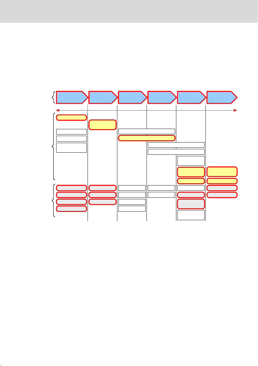
1 About this Documentation
Overview – target groups and product phases
The activities, product phases and target groups that refer to the present docu-
mentation are marked in red color in the following figure.
Example: In the product phase "Mounting (assembly/installation)", the "mechan-
ic/electrician" can execute the activity "install" using this documentation.
Fig. 1-1: Assigning the present documentation to the target groups, product phases and activities of the target group
Purpose
This document instructs the technical staff of the machine manufacturer on how
to perform the mechanic and electrical installation in a safe way and on how to
commission the device.
Required qualifications: Individual who is able to assess the tasks assigned and
identify possible safety risks owing to qualification in the subject, knowledge
and experience. The individual should also be familiar with the standards and
regulations.
Scope
This document is valid for all variants whose type code starts with "VR21xx.
01…".
The type code specifications are located on the type plate of the device, see al-
so chapter 2.1 "Product Identification" on page 2.
DOK-SUPPL*-VR21**.01**-IT02-EN-P
1/29

1
5
12
9
7
2
3
4
11
8
10
6
Bosch Rexroth AG
VR 21
Product Identification and Scope of Delivery
Further documents
Title Part number and document type
Rexroth IndraControl
VAP 01
R911339613
Operating Instructions
Power Supply Unit
Rexroth IndraControl
V Devices
R911343901
Project Planning Manual
Operating Systems
Tab. 1-1: Required and supplementing documentation
Customer feedback
Customer requests, comments or suggestions for improvement are of great im-
portance to us. Please email your feedback on the documentations to Feed-
back.Documentation@boschrexroth.de. Directly insert comments in the elec-
tronic PDF document and send the PDF file to Bosch Rexroth.
2
Product Identification and Scope of Delivery
2.1 Product Identification
The type plate is located on the rear panel.
1 Logotype
2 Part number
3 State of revision
4 Date of manufacture (yyWww)
5 Division or plant number
6 Designation of origin
Fig. 2-1: Type plate IndraControl VR 21
2.2 Scope of Delivery
● Product insert "Safety and Warning Instructions"
2/29
7 Nominal current
8 Serial number as barcode
9 Company address
10 Serial number
11 Nominal voltage
12 Type code (type designation code)
DOK-SUPPL*-VR21**.01**-IT02-EN-P

Burns and chemical burns due to wrong
battery treatment!
CAUTION
Safety alert symbol
Signal word
Consequences and
source of danger
Avoiding danger
Do not open the batteries and do not heat them over 80 °C.
DANGER
WARNING
VR 21
● Six mounting brackets including tool
● 24 V female connector strip
3 Using the Safety Instructions
3.1 Safety Instructions – Structure
The safety instructions are structured as follows:
Fig. 3-1: Safety instructions – Structure
Bosch Rexroth AG
Using the Safety Instructions
3.2 Explaining Signal Words and Safety Alert Symbol
The safety instructions in this documentation contain specific signal words (danger, warning, caution, notice) and, if necessary, a safety alert symbol (according
to ANSI Z535.6-2006).
The signal word is meant to draw the reader's attention to the safety instruction
and signifies the degree of danger.
The safety alert symbol (a triangle with an exclamation point), which precedes
the signal words danger,warning and caution is used to alert the reader to personal injury hazards.
In case of non-compliance with this safety instruction, death or serious injury
will occur.
In case of non-compliance with this safety instruction, death or serious injury
can occur.
DOK-SUPPL*-VR21**.01**-IT02-EN-P
3/29

CAUTION
NOTICE
NOTICE
Bosch Rexroth AG
Intended Use
In case of non-compliance with this safety instruction, minor or moderate injury
could occur.
In case of non-compliance with this safety instruction, property damage could
occur.
VR 21
3.3 Symbols Used
Notes are displayed as follows:
This is a note.
Tips are displayed as follows:
This is a tip.
4 Intended Use
The IndraControl VR 21 devices by Bosch Rexroth are machine operator panels
that can, depending on the application, visualize control data and trigger functions at the machine.
Danger of destruction of the device if not expressly stated accessories, mounting parts and
other components, cables, lines, software and
firmware are used
The machine operator panels may be used only as intended and with the accessories, mounting parts, and other components specified in this documentation.
Components that are not expressly mentioned must neither be attached nor
connected. The same applies to cables and lines.
Operation must only be carried out with the hardware component configurations and combinations that are expressly specified and with the software and
firmware indicated and specified in the respective documentation and functional descriptions.
Typical areas of application of the machine operator panels are:
● Handling systems and assembly systems
4/29
DOK-SUPPL*-VR21**.01**-IT02-EN-P

VR 21
Bosch Rexroth AG
Spare Parts, Accessories and Wear Parts
● Packaging and food processing machines
● Printing machines and paper converting machines
● Machine tools
● Wood processing machines
The machine operator panels may only be operated under the mounting and installation conditions, the position, and the ambient conditions (temperature, degree of protection, humidity, EMC etc.) specified in this documentation.
5 Spare Parts, Accessories and Wear Parts
5.1 External 24 V Power Supply Unit
Order code Parts number Description
VAP01.1H-W23-024-010-NN R911171065 External 24 V power supply unit for the
Tab. 5-1: External 24 V power supply unit for the operating panel
5.2 Wear Parts
Wear parts are not subject to any warranty.
Backlight
The service life of the backlight is limited. After this time has been exceeded,
the backlight will produce only 50 % of its original brightness. The service life of
the following table refers to an ambient temperature of 25 °C.
Display size
107.95 mm (4.3") 40,000 hours
177.8 mm (7") 40,000 hours
228.6 mm (9") 70,000 hours
IndraControl V devices
Service life
Tab. 5-2: Half-life period of the TFT displays
Touch screen
After 3 million touches, no damage or malfunction have occured under the fol-
lowing conditions:
Touch element: R8, HS40 silicone rubber
Touch pressure: 150 g
Touch frequency: 3 Hz
DOK-SUPPL*-VR21**.01**-IT02-EN-P
5/29
Loading...