


Rexroth IndraControl L25
Table of contents
 Loading...
Bosch Rexroth IndraControl L25, Rexroth IndraControl L65, Rexroth IndraControl L45, Rexroth IndraControl L85 Instruction Manual
Electric Drives
and Controls Pneumatics
Hydraulics
Linear Motion and
Assembly Technologies
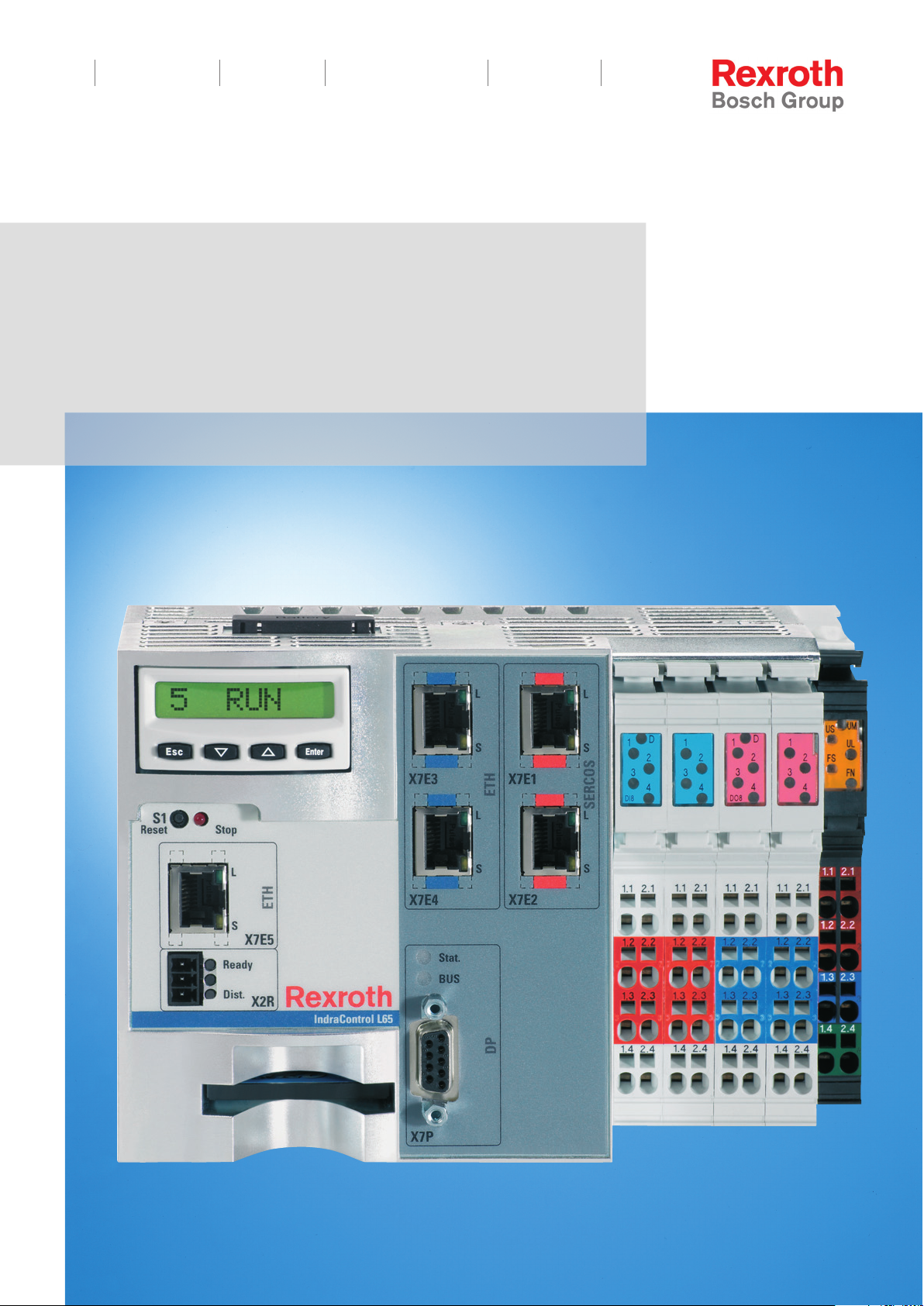
Rexroth IndraControl
L25, L45, L65 and l85
Controls
Instructions
Service
R911336525
Edition 01

Bosch Rexroth AG DOK-CONTRL-IC*LX5*****-IT01-EN-P
Rexroth IndraControl L25, L45, L65 and L85 Controls
Title
Type of Documentation
Document Typecode
Internal File Reference
Record of Revision
Copyright
Liability
Published by
Note
Rexroth IndraControl
L25, L45, L65 and L85
Controls
Instructions
DOK-CONTRL-IC*LX5*****-IT01-EN-P
RS-65021c30ed05e1790a6846a50196054e-1-en-US-4
Edition Release Date Notes
First edition 01.2012 --
© Bosch Rexroth AG 2012
This document, as well as the data, specifications and other information set
forth in it, are the exclusive property of Bosch Rexroth AG. It may not be re‐
produced or given to third parties without its consent.
The specified data is intended for product description purposes only and shall
not be deemed to be a guaranteed characteristic unless expressly stipulated
in the contract. All rights are reserved with respect to the content of this docu‐
mentation and the availability of the product.
Bosch Rexroth AG
Bgm.-Dr.-Nebel-Str. 2 ■ 97816 Lohr am Main, Germany
Phone +49 9352 18 0 ■ Fax +49 9352 18 8400
http://www.boschrexroth.com/
Development automation systems control platform SR (CS)
This document has been printed on chlorine-free bleached paper.

DOK-CONTRL-IC*LX5*****-IT01-EN-P
Rexroth IndraControl L25, L45, L65 and L85 Controls
Bosch Rexroth AG I/65
Table of Contents
Table of Contents
Page
1 About this Documentation.............................................................................................. 5
2 Product Identification and Scope of Delivery................................................................. 7
2.1 Product Identification.............................................................................................................................. 7
2.2 Scope of Delivery.................................................................................................................................... 7
3 Using the Safety Instructions......................................................................................... 9
3.1 Safety instructions – structure................................................................................................................. 9
3.2 Explaining Signal Words and Safety Alert Symbol................................................................................. 9
4 Intended Use................................................................................................................ 11
5 Spare Parts, Accessories, and Wear Parts.................................................................. 13
5.1 Connector Set for the L45, L65, L85 Control........................................................................................ 13
5.2 Connector Set for the L25 Control........................................................................................................ 13
5.3 Fan for the L45, L65 and L85 Control................................................................................................... 13
5.4 Battery for the L45, L65 and L85 Control.............................................................................................. 13
5.5 Display Set............................................................................................................................................ 13
5.6 Cap for Compact Flash Slot.................................................................................................................. 13
5.7 Power Supply Unit ............................................................................................................................... 14
5.8 Wear Parts............................................................................................................................................ 14
6 Ambient Conditions...................................................................................................... 15
7 Technical Data............................................................................................................. 17
8 Standards..................................................................................................................... 19
8.1 Used Standards.................................................................................................................................... 19
8.2 CE Mark................................................................................................................................................ 19
8.2.1 Declaration of Conformity ................................................................................................................. 19
8.3 UL/CSA Certified.................................................................................................................................. 19
9 Interfaces..................................................................................................................... 21
9.1 Interface View....................................................................................................................................... 21
9.2 Overview............................................................................................................................................... 22
10 Mounting, Dismounting and Electrical Installation....................................................... 25
10.1 Installation Notes.................................................................................................................................. 25
10.2 Housing Dimensions............................................................................................................................. 26
10.3 Mounting the Control............................................................................................................................ 30
10.4 Mounting the Fan (if Necessary)........................................................................................................... 34

II/65
Table of Contents
10.5 Dismounting the Control....................................................................................................................... 34
10.6 Dismounting and changing the Inline terminals.................................................................................... 36
10.7 Electrical Installation............................................................................................................................. 38
10.7.1 General Information........................................................................................................................... 38
10.7.2 External Power Supply Unit .............................................................................................................. 38
10.7.3 Voltage Supply for the Control........................................................................................................... 38
10.7.4 24 V Voltage Supply.......................................................................................................................... 40
10.7.5 Grounding
10.7.6 Shielding............................................................................................................................................ 42
10.7.7 Connecting Lines (for Digital Onboard Inputs, Outputs and Voltage Supply) to Tension Spring Con‐
10.7.8 Notice for Use of the Control above 2700 m above MSL.................................................................. 43
10.7.9 Digital Onboard Inputs on Controls L45, L65 and L85...................................................................... 44
10.7.10 Digital Onboard Outputs on Controls L45, L65 and L85.................................................................... 45
10.7.11 Further Interfaces.............................................................................................................................. 46
Bosch Rexroth AG DOK-CONTRL-IC*LX5*****-IT01-EN-P
Rexroth IndraControl L25, L45, L65 and L85 Controls
Page
........................................................................................................................................................... 41
nection Points.................................................................................................................................... 42
11 Commissioning............................................................................................................ 47
12 Device Description....................................................................................................... 49
12.1 General Information.............................................................................................................................. 49
12.2 Display Elements.................................................................................................................................. 49
13 Error Causes and Error Elemination............................................................................ 51
14 Maintenance................................................................................................................ 53
14.1 General Information.............................................................................................................................. 53
14.2 Regular Maintenance............................................................................................................................ 53
14.3 Display (LCD Display)........................................................................................................................... 53
14.4 Lithium Battery...................................................................................................................................... 53
15 Ordering Information.................................................................................................... 55
15.1 Accessories and Spare Parts............................................................................................................... 55
15.2 Type Designation Code L25................................................................................................................. 55
15.3 Type Designation Code L45................................................................................................................. 56
15.4 Type Designation Code L65................................................................................................................. 57
15.5 Type Designation Code L85................................................................................................................. 58
16 Disposal....................................................................................................................... 59
16.1 General Information.............................................................................................................................. 59
16.2 Take-Back............................................................................................................................................. 59
16.3 Package................................................................................................................................................ 59
16.4 Batteries and Accumulators.................................................................................................................. 59

DOK-CONTRL-IC*LX5*****-IT01-EN-P
Rexroth IndraControl L25, L45, L65 and L85 Controls
Bosch Rexroth AG III/65
Table of Contents
Page
17 Service and Support.................................................................................................... 61
Index............................................................................................................................ 63

IV/65
Bosch Rexroth AG DOK-CONTRL-IC*LX5*****-IT01-EN-P
Rexroth IndraControl L25, L45, L65 and L85 Controls

Selection
Enginee ring
Design engineer
Mechanic/
electrician
Se rvic e
Pres ales Aftersa le s
Mounting
Product
phases
Target
groups
Activities
(assembly/installation)
Commissioning
Operation
Decommissioning
Programmer
Technologist
Process
specialist
Programmer
Commissioning engineer
Technologist
Process specialist
Machine
operator
Maintenance
technician
Mechanic/
electrician
Disposal company
To select
To prepare
To design
To construct
To unpack
To mount
To install
To parameterize
To program
To configure
To simulate
To optimize
To test
To operate
To maintain
To remove
faults
To create
the NC program
To dismount
To dispose
DOK-CONTRL-IC*LX5*****-IT01-EN-P
Rexroth IndraControl L25, L45, L65 and L85 Controls
1 About this Documentation
Bosch Rexroth AG 5/65
About this Documentation
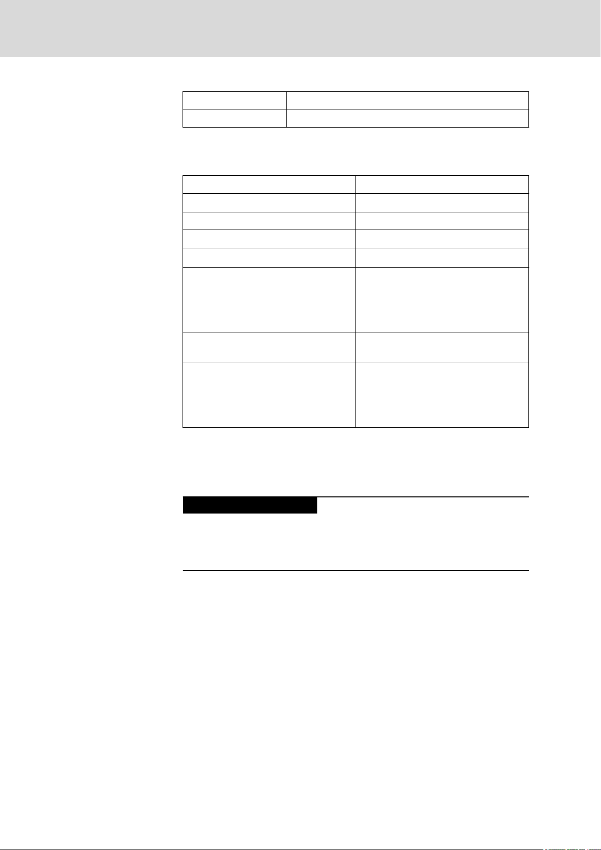
Overview – target groups and
product phases
The activities, product phases and target groups that refer to the present doc‐
umentation are marked in red color in the following figure.
Example: In the product phase "Mounting (assembly/installation)", the target
group "mechanic/electrician" can execute the activity "install" using this docu‐
mentation.
Availability
Scope
Fig.1-1: Assigning the present documentation to the target groups, product
phases and activities of the target group
This document instructs the technical staff of the machine manufacturer on
how to perform the mechanic and electrical installation in a safe way and on
how to commission the device.
Required qualifications: Individual who is able to assess the tasks assigned
and identify possible safety risks owing to qualification in the subject, knowl‐
edge and experience. The individual should also be familiar with the stand‐
ards and regulations.
This document is part of the present product delivery. This document has to
be available to the user at any time. The product has to be passed on togeth‐
er with this document only.
This document is valid for all variants of the control, whose type designation
code starts with:
CML25.1...
CML45.1...
CML65.1...
CML85.1...
The type designation code specifications are located on the type plate of the
device, see also chapter 2 "Product Identification and Scope of Delivery" on
page 7.
6/65
Bosch Rexroth AG DOK-CONTRL-IC*LX5*****-IT01-EN-P
About this Documentation
Rexroth IndraControl L25, L45, L65 and L85 Controls
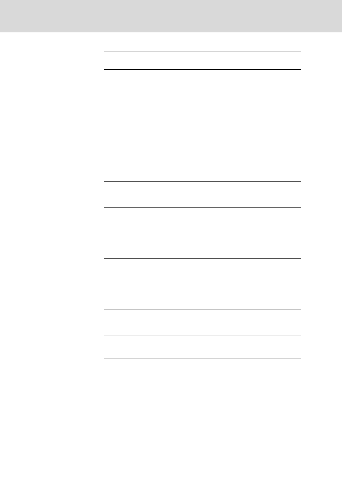
Further documents
Title Code (part short text) and
type of documentation
PLC Programming with
Rexroth IndraLogic 1.0
RECO-Inline PROFIBUS
DP
(Rexroth-Inline PROFIBUS
DP)
RECO Inline PROFIBUS DP
Terminal and Module Sup‐
ply
(Rexroth Inline PROFIBUS
DP Terminal and Module
Supply)
Rexroth IndraWorks xxVRS
Engineering
Automation Terminals of the
Rexroth Inline Product
Range
DOK-CONTRLIL**PRO*V01-AWxx-EN-P
Operating and Programming
Guide
DOK-CONTRL-R-ILPBSSYS-AWxx-EN-P
Application Manual
DOK-CONTRL-R-IL-PB*BK-FKxx-EN-P
Application Manual
DOK-IWORKS-ENGIN‐
EE*Vxx-AWxx-EN-P
Application Manual
DOK-CONTRL-ILSY‐
SINS***-AWxx-EN-P
Application Manual
1)
Parts number
R911305036
R911289597
R911289587
R911327718
R911317021
Rexroth IndraControl L
Function Modules
Rexroth IndraWorks xxVRS
IndraLogic 2G
Rexroth IndraControl L25 DOK-CONTRL-IC*L25*****-
Rexroth IndraControl L45,
L65, L85
A Lx5 control is required to operate a MLC, IndraLogic, MTX, MLC, XLC or an
IndraLogic component. Therefore do also observe the documentation of the relevant
system.
DOK-CONTRL-IC*L*FM****PRxx-EN-P
Project Planning Manual
DOK-CONTRLIL2GPRO*Vxx-APxx-EN-P
Application Manual
PRxx-EN-P
Project Planning Manual
DOK-CONTRLICL45L65L85-PRxx-EN-P
Project Planning Manual
R911326408
R911325440
R911328474
R911332116
Fig.1-2: Further documents
For further documents, please enter the specified parts number under "Docu‐
mentation and Downloads" in the "Rexroth Media Directory" at http://
www.boschrexroth.com.
The documents are updated regularly on the internet.
1)
xx is the placeholder for the relevant edition of the documentation.
MA6/210-7402-M
U
N
IN 3AC 230V 50/60 Hz
I
N
OUT 10/7,5/5/5/1,5/1,5 A max.
I-C-B-T-V
SW-Vers ion V0,002
MNR: 1070086300 -105 04W03
1070
13026
2
3
6
7
7
10
11
12
13
14
9
8
5
4
1
Bosch rexroth Electric Drives and Controls GmbH
D-64711 Erbach Made in Germany
BTV40.1AHB-256S-P5CUN-FW
UN IN 3AC 230V 50760Hz
IN
OUT 10/7,5/5/5/1,5/1,5A max.
I-C-B-T-V
SW-Version V0,002
MNR: 1070170021 -101 03W19
7261
IND.CONT.EQ 17YB
SN: 123456814
15
16
Made in Germany
UN: AC 230V / 115V
IN: 0,7A / 1,4A
MNR: 1070086255 -101
V-Nr: 1
TYP: PCPNL PEN400J1287 IS110-T
Bosch Rexroth Electric Drives and Controls GmbH
D-6471
1 Erbach
SN: 004012652
7261
IND.CONT-EQ 17YB
XXXXXXXXXXXXXXXXX
I-C-B-H-T-V
FD: 05W01
1
2
3
4
8
9
5
10
6
12
11
13
14
15
16
DOK-CONTRL-IC*LX5*****-IT01-EN-P
Bosch Rexroth AG 7/65
Rexroth IndraControl L25, L45, L65 and L85 Controls
Product Identification and Scope of Delivery
2 Product Identification and Scope of Delivery
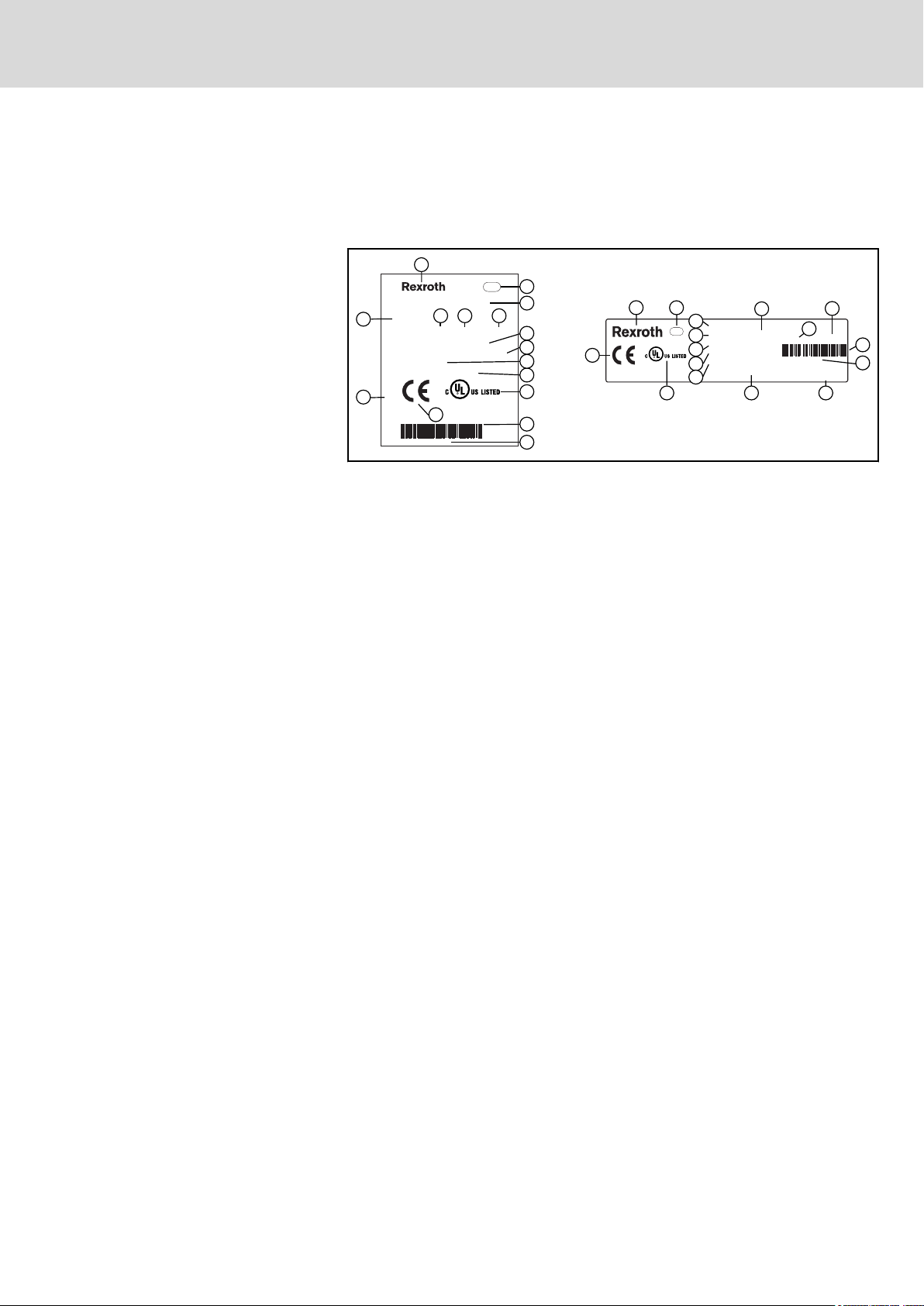
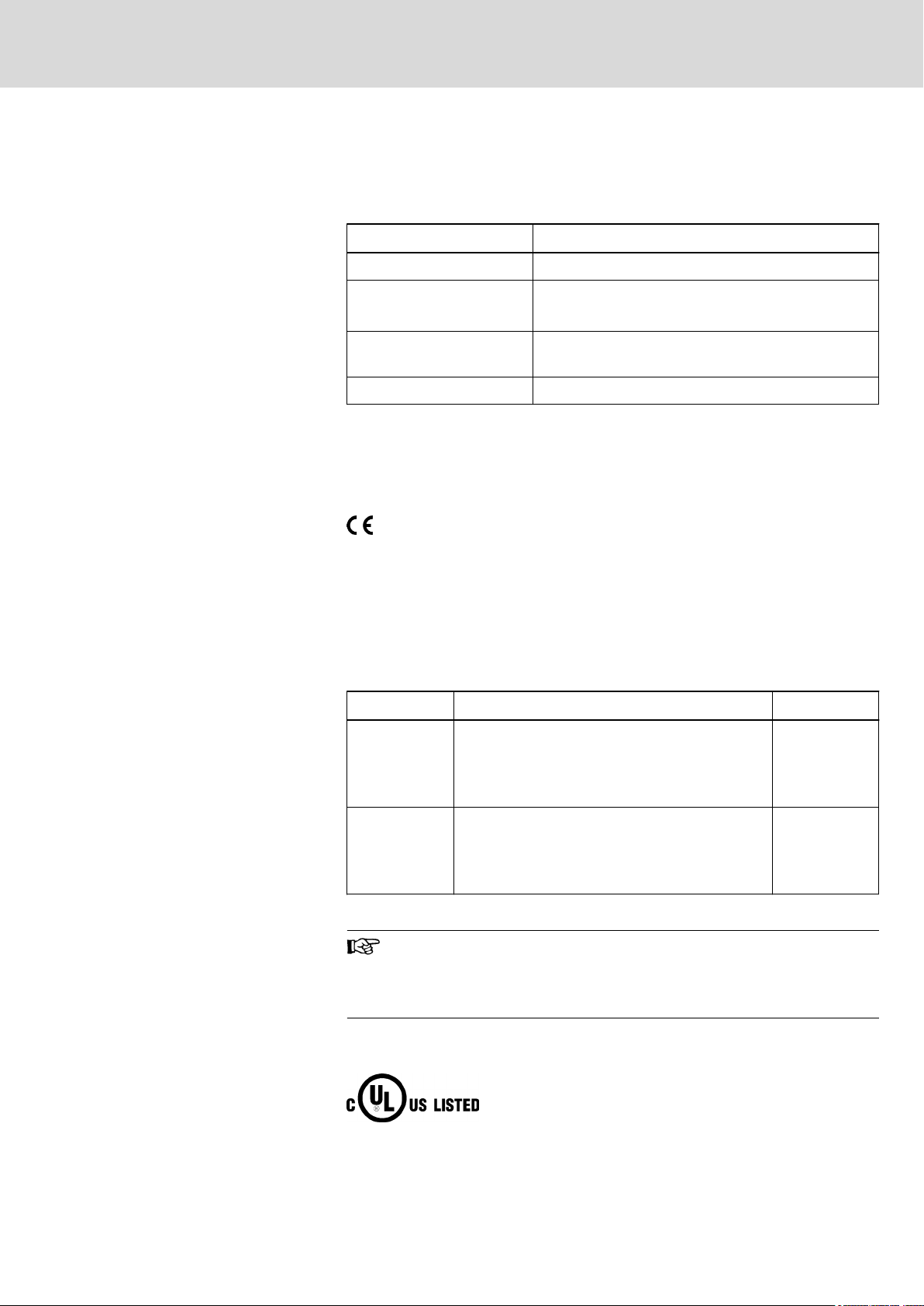
2.1 Product Identification
The type plate is located on the back side.
1 Logotype
2 Division or plant number
3 Type code (type designation code)
4 Parts number
5 State of revision
6 Date of manufacture (yyWww)
7 Nominal voltage
8 Nominal current
9 Test marking
10 Version number
11 CE marking
12 Underwriters Laboratories Inc. mark
13 Barcode
14 Serial number
15 Designation of origin
16 Company address
Fig.2-1: Type plates, example
2.2 Scope of Delivery
● Control
● Instructions
● Fan (only included in the scope of delivery of control L85)
● Power connector (only included in the scope of delivery of control L25)
● End clamp
● EMI shielding
● Female connector strip (already mounted)
● Antistatic bag
● Lithium battery (already inserted)
1)
Not included in the scope of delivery of the controls with parts numbers
R911170827 and R911170899.
2)
Only included in the scope of delivery of control L85 and the controls with parts
numbers R911170827 and R911170899.
1)
1)
1)
1)
2)

8/65
Bosch Rexroth AG DOK-CONTRL-IC*LX5*****-IT01-EN-P
Rexroth IndraControl L25, L45, L65 and L85 Controls
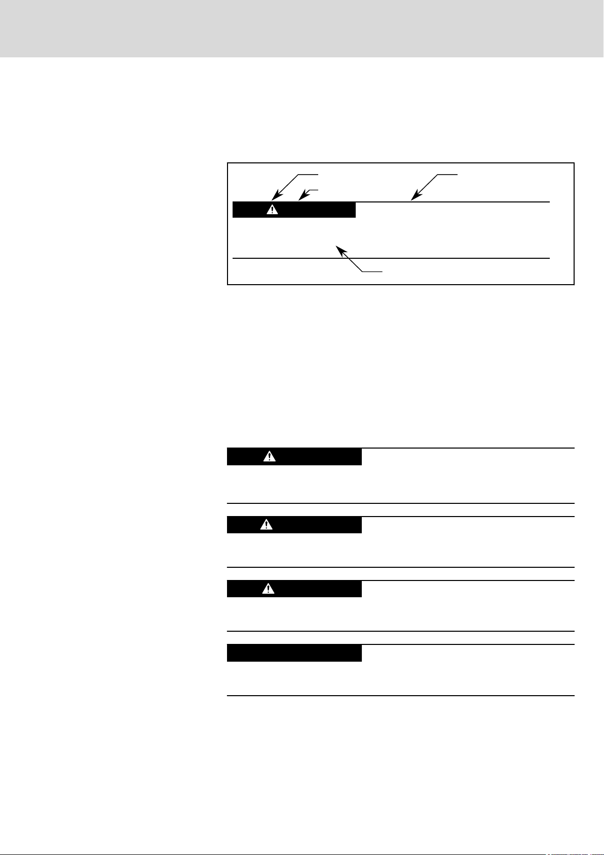
Burns and chemical burns due to wrong
battery treatment!
CAUTION
Safety alert symbol
Signal word
Consequences and
source of danger
Avoiding danger
Do not open the batteries and do not heat them over 80 °C.
DANGER
WARNING
CAUTION
NOTICE
DOK-CONTRL-IC*LX5*****-IT01-EN-P
Rexroth IndraControl L25, L45, L65 and L85 Controls
3 Using the Safety Instructions
3.1 Safety instructions – structure
The safety instructions are structured as follows:
Fig.3-1: Safety instructions – structure
Bosch Rexroth AG 9/65
Using the Safety Instructions
3.2 Explaining Signal Words and Safety Alert Symbol
The safety instructions in this documentation contain specific signal words
(danger, warning, caution, notice) and, if necessary, a safety alert symbol
(according to ANSI Z535.6-2006).
The signal word is meant to draw the reader's attention to the safety instruc‐
tion and signifies the degree of danger.
The safety alert symbol (a triangle with an exclamation point), which pre‐
cedes the signal words danger,warning and caution is used to alert the read‐
er to personal injury hazards.
In case of non-compliance with this safety instruction, death or serious injury
will occur.
In case of non-compliance with this safety instruction, death or serious injury
can occur.
In case of non-compliance with this safety instruction, minor or moderate in‐
jury could occur.
In case of non-compliance with this safety instruction, property damage could
occur.

10/65
Bosch Rexroth AG DOK-CONTRL-IC*LX5*****-IT01-EN-P
Rexroth IndraControl L25, L45, L65 and L85 Controls

NOTICE
DOK-CONTRL-IC*LX5*****-IT01-EN-P
Rexroth IndraControl L25, L45, L65 and L85 Controls
4 Intended Use
The control may only be used with the accessories and mounting parts listed
in this documentation. Components that are not expressly mentioned must
neither be attached nor connected. The same is valid for cables and lines.
Operation must only be carried out with the hardware component configura‐
tions and combinations that are expressly specified and with the software and
firmware indicated and specified in the respective documentation and func‐
tional descriptions.
Typical fields of use of the controls are:
● Handling systems and assembly systems
● Packaging and food processing machines
● Printing machines and paper converting machines
● Machine tools
● Woodworking machines
The controls may only be operated under the mounting and installation condi‐
tions, the position, and the ambient conditions (temperature, degree of pro‐
tection, humidity, EMC etc.) specified in this documentation.
Bosch Rexroth AG 11/65
Intended Use
Danger of destruction of the device if not ex‐
pressly stated accessories, mounting parts
and other components, cables, lines, soft‐
ware and firmware are used.

12/65
Bosch Rexroth AG DOK-CONTRL-IC*LX5*****-IT01-EN-P
Rexroth IndraControl L25, L45, L65 and L85 Controls
DOK-CONTRL-IC*LX5*****-IT01-EN-P
Rexroth IndraControl L25, L45, L65 and L85 Controls
Spare Parts, Accessories, and Wear Parts
Bosch Rexroth AG 13/65
5 Spare Parts, Accessories, and Wear Parts
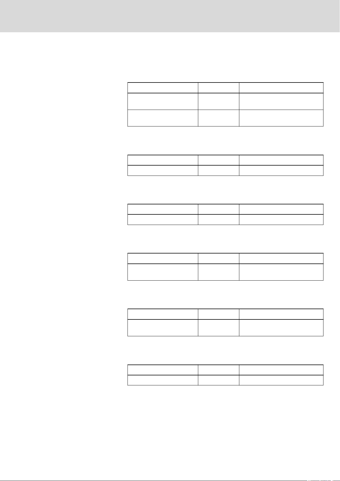
5.1 Connector Set for the L45, L65, L85 Control
Order code Parts number Description
R-IB IL CML S01 PLSET R911299856 2 input, 2 output and 1 power con‐
nector
R-IB IL CML S04 PLSET R911172193 2 input, 2 output and 1 power con‐
nector, continuously numbered
Fig.5-1: Connector set for the L45, L65 and L85 control
5.2 Connector Set for the L25 Control
Order code Parts number Description
R-IB IL SCN-PWR IN PWR R911171765 -
Fig.5-2: Power connector for the L25 control
5.3 Fan for the L45, L65 and L85 Control
Order code Parts number Description
CAL01.1-F2 R911171153 -
Fig.5-3: Fan for the L45, L65 and L85 control
5.4 Battery for the L45, L65 and L85 Control
Order code Parts number Description
CAP01.1-B2 R911170806 3 V lithium battery for onboard
Fig.5-4: Battery for the L45, L65 and L85 control
5.5 Display Set
Order code Parts number Description
CAL03.1-D1 R911172142 Display exchange set for the con‐
Fig.5-5: Display set for the control
SRAM
trols
5.6 Cap for Compact Flash Slot
Order code Parts number Description
CAL02.1-S1 R911171617 Cap for Compact Flash slot
Fig.5-6: Cap for Compact Flash slot

14/65
Spare Parts, Accessories, and Wear Parts
Bosch Rexroth AG DOK-CONTRL-IC*LX5*****-IT01-EN-P
5.7 Power Supply Unit
Order code Parts number Description
VAP01.1H-W23-024-010-NN R911171065 24 V power supply unit
Fig.5-7: Power supply unit
5.8 Wear Parts
Wear parts are not subject to any warranty.
Display
3 V lithium battery
The service life of the display is limited. A progressive deterioration takes
place after the service life has been exceeded.
Service life:
● 60,000 hours at a temperature of 23℃ (± 5°C) and a relative air humidi‐
ty of 60% RH (± 20% RH).
Service life: At least five years.
Fan
Fans are mechanical components subject to wear. The service life of the fan
depends particularly on the temperature.
Service life of the fan:
● 95,000 hours at 24 °C.
The fan operating hours counter can be read via the control.
Rexroth IndraControl L25, L45, L65 and L85 Controls
NOTICE
DOK-CONTRL-IC*LX5*****-IT01-EN-P
Rexroth IndraControl L25, L45, L65 and L85 Controls
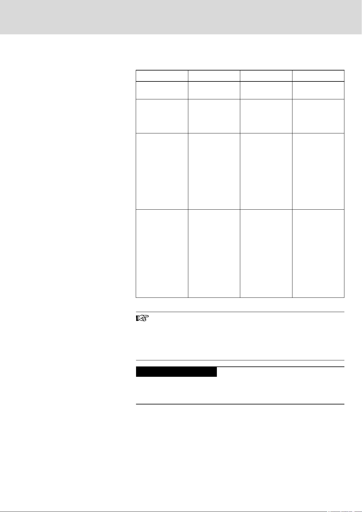
6 Ambient Conditions
In operation Transport Storage
Bosch Rexroth AG 15/65
Ambient Conditions
Max. surrounding
air temperature
Relative humidity RH -2; 5 % to 95 %
Air pressure Up to 2,700 m
Mechanical
strength
+5 ℃ to +55 ℃ -25 ℃ to +70 ℃ -25 ℃ to +70 ℃
according to DIN
EN 61131-2,
non-condensing.
above MSL accord‐
ing to DIN 60204.
Above 2700 m
above MSL, see
chapter 10.7.8
"Notice for Use of
the Control above
2700 m above
MSL" on page 43.
Max. vibration:
Frequency range:
10 Hz to 150 Hz
Excursion:
0.075 mm
at 10 Hz to 57 Hz
Acceleration: 1 g
at 57 Hz to 150 Hz
acc. to EN
60068-2-6
RH -2; 5 % to 95 %
according to DIN
EN 61131-2,
non-condensing.
Up to 3000 m
above MSL accord‐
ing to DIN 60204.
Above 2700 m
above MSL, see
chapter 10.7.8
"Notice for Use of
the Control above
2700 m above
MSL" on page 43.
Max. shock:
15 g acc. to
EN 60 068-2-27, no
disturbance of the
function.
RH -2; 5 % to 95 %
according to DIN
EN 61131-2,
non-condensing.
Up to 3000 m
above MSL accord‐
ing to DIN 60204.
Above 2700 m
above MSL, see
chapter 10.7.8
"Notice for Use of
the Control above
2700 m above
MSL" on page 43.
Max. shock:
15 g acc. to
EN 60 068-2-27, no
disturbance of the
function.
Notice for control L25
Fig.6-1: Ambient conditions
The surrounding air must be free from acids, alkaline solutions,
corrosive agents, salts, metal vapors, and other electrically con‐
ductive contaminants in high concentrations.
The ambient air must be dust-free. Housings and installation com‐
partments must at least comply with degree of protection IP 54
according to DIN VDE 0470-1.
Production failure possible due to control fail‐
ure resulting from overheating.
Operation is allowed up to 55 ℃ and if the air recirculates. If the air does not
recirculate, the fan has to be used.
If the internal temperature is 87 ℃ or higher, the display indicates the
"Temp !!!" warning.
If the internal temperature reaches approx. 92 ℃, the control switches off au‐
tomatically.
NOTICE
16/65
Bosch Rexroth AG DOK-CONTRL-IC*LX5*****-IT01-EN-P
Ambient Conditions
Notice for control L45, L65 and
Notice for control L85
Rexroth IndraControl L25, L45, L65 and L85 Controls
Use the "IH_Temperature" function to read out the internal control tempera‐
ture in the "RIH_CMLx.library" library of the "IndraWorks" application program
(from version 11), see also documentation Rexroth IndraWorks 12VRS Basic
Libraries IndraLogic 2G, ( DOK-IL*2G*-BASLIB**V12-LI01-EN-P, parts num‐
ber R911333835).
L85
Production failure possible due to control fail‐
ure resulting from overheating.
Operation is allowed up to 55 ℃ and if the air recirculates. If the air does not
recirculate, the fan has to be used.
If the internal temperature is 70 ℃ or higher, the display indicates the
"Temp !!!" warning.
If the internal temperature reaches approx. 80 ℃, the control switches off au‐
tomatically.
Use the "IH_Temperature" function to read out the internal control tempera‐
ture in the "RIH_CMLx.library" library of the "IndraWorks" application program
(from version 11), see also documentation Rexroth IndraWorks 12VRS Basic
Libraries IndraLogic 2G, ( DOK-IL*2G*-BASLIB**V12-LI01-EN-P, parts num‐
ber R911333835).
With the IndraControl L85 control, the fan is included in the scope
of delivery and is imperatively necessary for its operation. Infor‐
mation on the fan assembly is contained in chapter 10.4 "Mount‐
ing the Fan (if Necessary)" on page 34.
DOK-CONTRL-IC*LX5*****-IT01-EN-P
Rexroth IndraControl L25, L45, L65 and L85 Controls
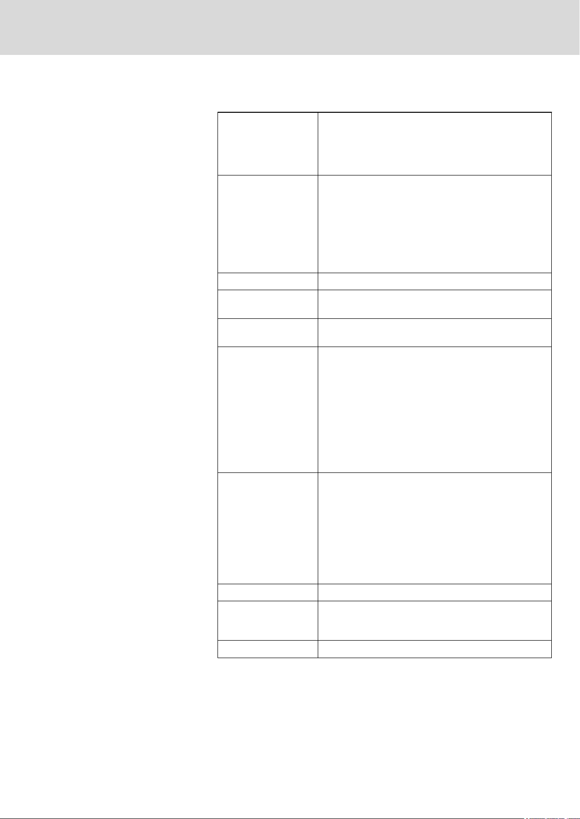
7 Technical Data
Processor Control L25: Renesas SH7785 with 576 MHz (CPU CLK)
RAM Controls L45, L65 and L85:
Interfaces:
Interface to function
modules
Bosch Rexroth AG 17/65
Technical Data
Control L45: AMD LX800 with 500 MHz
Control L65: Intel Celeron M with 1.0 GHz
Control L85: Intel Core2Duo with 1.2 GHz
Min. 256 MByte DRAM and min. 256 kByte RDS
Optional:
● 8 or 16 MByte SRAM battery buffered
Control L25:
Min. 128 MByte DRAM and min. 256 kByte RDS
● Rexroth PC104
Plus
1)
1)
Interface to
I/O terminals
Communication interfa‐
ces
(on L45, L65 and L85)
Communication interfa‐
ces
(on L25)
Ready Contact ● 1 × single-pin ready contact
● Rexroth Inline interface
● 1 × Ethernet connection (RJ 45, 10Base-T,
100Base-TX)
Optional:
● 1 × third generation sercos master/slave interface
Optional:
● 1 × PROFIBUS DP master/slave interface
● 2 × Ethernet connection (RJ 45, 10Base-T, 100
Base-TX) for TCP/IP or RT Ethernet (PROFINET RT
or EtherNet/IP)
● 1 × Ethernet connection (RJ 45, 10/100 base-T)
● 1 × third generation sercos master/slave interface
● Alternative option to the sercos master/slave inter‐
face
- 1 × PROFIBUS DP master/slave interface or
- 2 × Ethernet connection (RJ 45, 10Base-T, 100
Base-TX) for TCP/IP or RT Ethernet (PROFINET RT
or EtherNet/IP)
Digital inputs and out‐
puts (only on L45, L65
and L85)
Weight 1.8 kg
1)
RDS - Remanent Data Storage
● 8 × electrically isolated digital inputs
● 8 × electrically isolated digital outputs
Remanent data is automatically written to the Compact Flash card after loss of
voltage and is restored after rebooting the control.
NOTICE
18/65
Bosch Rexroth AG DOK-CONTRL-IC*LX5*****-IT01-EN-P
Technical Data
Voltage supply and current, power
consumption
Rexroth IndraControl L25, L45, L65 and L85 Controls
Degree of protection IP 20
Dimensions See chapter 10.2 "Housing Dimensions" on page 26
Fig.7-1: Technical data
The control is supplied with 24 V. The following values according to
DIN EN 61131-2 apply to the operating voltage:
Nominal voltage DC 24 V
Tolerance -15 %, +20 % (without residual ripple)
Residual ripple ±5 %
U
max
U
min
Power consumption of the controls from
ULS at nominal voltage and all connected
function modules and Inline terminals
Current consumption of the controls from
UM and U
Power consumption (typically) of the con‐
trols (without connected I/O and function
modules)
S
30 V
19.2 V
Control L25: 2 A max.
Control L 45: 2.6 A max.
Control L65: 3.0 A max.
Control L85: 3.0 A max.
Max. 8 A in total
Control L25: 8.7 W
Control L45: 14 W
Control L65: 18 W
Control L85: 21 W
Fig.7-2: Operating voltage and current, power consumption
Three operating voltages (segment voltage US, the supply voltage ULS and
the main voltage UM) are to be applied to the control, see also chapter 10.7.4
"24 V Voltage Supply" on page 40.
Possible production failures due to malfunc‐
tions caused by feed backwards due to un‐
connected ground terminal.
Ensure that a ground terminal is always connected. In this way malfunctions
that are caused by feed backwards via I/O signals can be avoided.
DOK-CONTRL-IC*LX5*****-IT01-EN-P
Rexroth IndraControl L25, L45, L65 and L85 Controls
8 Standards
8.1 Used Standards
Standard Description
DIN EN 60 204-1 Electrical equipment of machines
DIN EN 61 131-2 Programmable logic controllers
DIN EN 60 529 Degrees of protection (including housings and installa‐
UL 508 Industrial Control Equipment
Fig.8-1: Used standards
8.2 CE Mark
Bosch Rexroth AG 19/65
Standards
Equipment and tests requirements
tion compartments)
8.2.1 Declaration of Conformity
The electronic products described in these instructions comply with the re‐
quirements and targets of the following EU Directive and with the harmonized
European standards:
EMC Directive 2004/108/EC
The electronic products described in the present instructions are intended for
operation in industrial environments and comply with the following require‐
ments:
Standard Title Issue
DIN EN 610006-4
(VDE 0839-6-4
)
DIN EN 610006-2
(VDE 0839-6-2
)
Fig.8-2: Standards on the electromagnetic compatibility (EMC)
Electromagnetic compatibility (EMC)
Part: 6-4: Generic standards – Emission standard
for industrial environments (IEC 61000-6-4:2006)
Electromagnetic compatibility (EMC)
Part: 6-2: Generic standards – Noise immunity for
industrial environments (IEC 61000-6-2:2005)
September
2007
March 2006
8.3 UL/CSA Certified
The devices are certified according to
● UL508 (Industrial Control Equipment) and
Loss of CE conformity due to changes to the device.
The CE marking is only valid for the device in its delivery status.
After having modified the device, the CE conformity is to be veri‐
fied.
Loading...