


Rexroth VT-VSPA1-1
Electrical amplifiers
Type VT-VSPA1-1 and VT-VSPA1K-1
Component series 1X
RE 30111/09.05
Replaces: 02.03
H5897_d
1/12
Table of contents
Contents Page
Features 1
Ordering code 2
Functional description 2 and 3
Block circuit diagram / pin assignment VT-VSPA1-1 4
Block circuit diagram / pin assignment VT-VSPA1K-1 5
Technical data 6
Output characteristic curves 7
Indicator / adjustment elements 8 and 9
Meaning of DIL switches 10
Unit dimensions 11
Engineering / maintenance notes / supplementary in for ma tio n 11
Troubleshooting 12
Features
– Suitable for controlling all direct and pilot operated proportion-
al pressure control valves without electrical position feedback
and only one solenoid as actuator that are available at the time
of publication of this data sheet
– Differential input, can be switched between voltage and cur-
rent input
– Additional command value input, 0 to +9 V
–
Ramp generator, can be adjusted separately for up and down ramps
– Clocked output stage
– Signal "ready for operation" (VT-VSPA1K-1 only with LED
indicator lamp)
– Reverse polarity protection for voltage supply
– Cable break detection of current input 4 to 20 mA
– Short-circuit protection of solenoid cable
– Cable break detection of solenoid cable
Suitable card holders for VT-VSPA1-1:
– Type VT 3002-2X/32, see RE 29928
Single card holder without power supply unit
Suitable power supply unit:
– Type VT-NE30-1X, see RE 29929
Compact power supply unit 115/230 VAC → 24 VDC, 108
W
2/12 Bosch Rexroth AG Hydraulics
Ordering code
VT-VSPA1-1 and VT-VSPA1K-1
RE 30111/09.05
VT-VSPA1 1 1X
Amplifiers for controlled proportional pressure
control valves, analogue, with one solenoid
With 32-pin male connector and front panel = No code
With 16-pin terminal strip; without front panel = K
Functional description
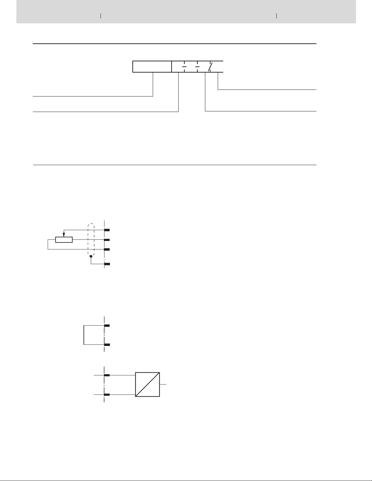
The command value voltage is applied to command value input
1 either directly or via an external command value potentiometer
with
the help of the regulated + 9V voltage from the power supply
unit [14].
The following is valid for this input: +9 V +100 % 1).
External command value feedforward
12(ac)
5K
Note:
When an external command value potentiometer is used, in ter nal potentiometer "Gw" [3] must be set to maximum or the
required maximum pressure.
Internal command value feedforward
Differential input (input 2)
10(ac)
14(ac)
18(ac)
12(ac)
10(ac)
Input 1
+9 V
M0
Input 1
+9 V
*
Further details in clear text
1X = Component series 10 to 19
(10 to 19: unchanged technical data and pin
assignment)
For substitutes for amplifier types VT 2000 (up to
component series 4X), VT 2010, VT 2013 or VT 2023
for rack installation, blind plate 4TE/3HE must be ordered separately. Material no. R900021004
Command value input 2 is a differential input [1] (0 to + 10 V).
With the help of DIL switches
rent input (4 to 20 mA or 0 to + 20 mA). If the command value
is fed forward by external electronics with a different reference
potential (e.g. by a PLC), this input must be used. When the
command value voltage is applied or withdrawn, care must be
taken that both signal cables are disconnected from or connected to the input.
Before being passed on, both command values are summated
[2] and then fed to a potentiometer [3] that is accessible on
the front pan el and acts as attenuator and limits the maximum
com mand value.
The downstream ramp generator [4] generates a ramp-shaped
out put signal from a stepped input signal. The time constant
of this signal can be adjusted separately for “up” and “down”
ramps with the help of two potentiometers. The specifi ed ramp
time refers to a command value step-change of 100% and can
be approx. 1 s or 5 s, depending on the setting of a DIL switch 2).
If a command value step-change of less than 100 % is fed to
the input of the ramp generator or when attenuator [3] is effective, the ramp time shortens ac cord ing ly
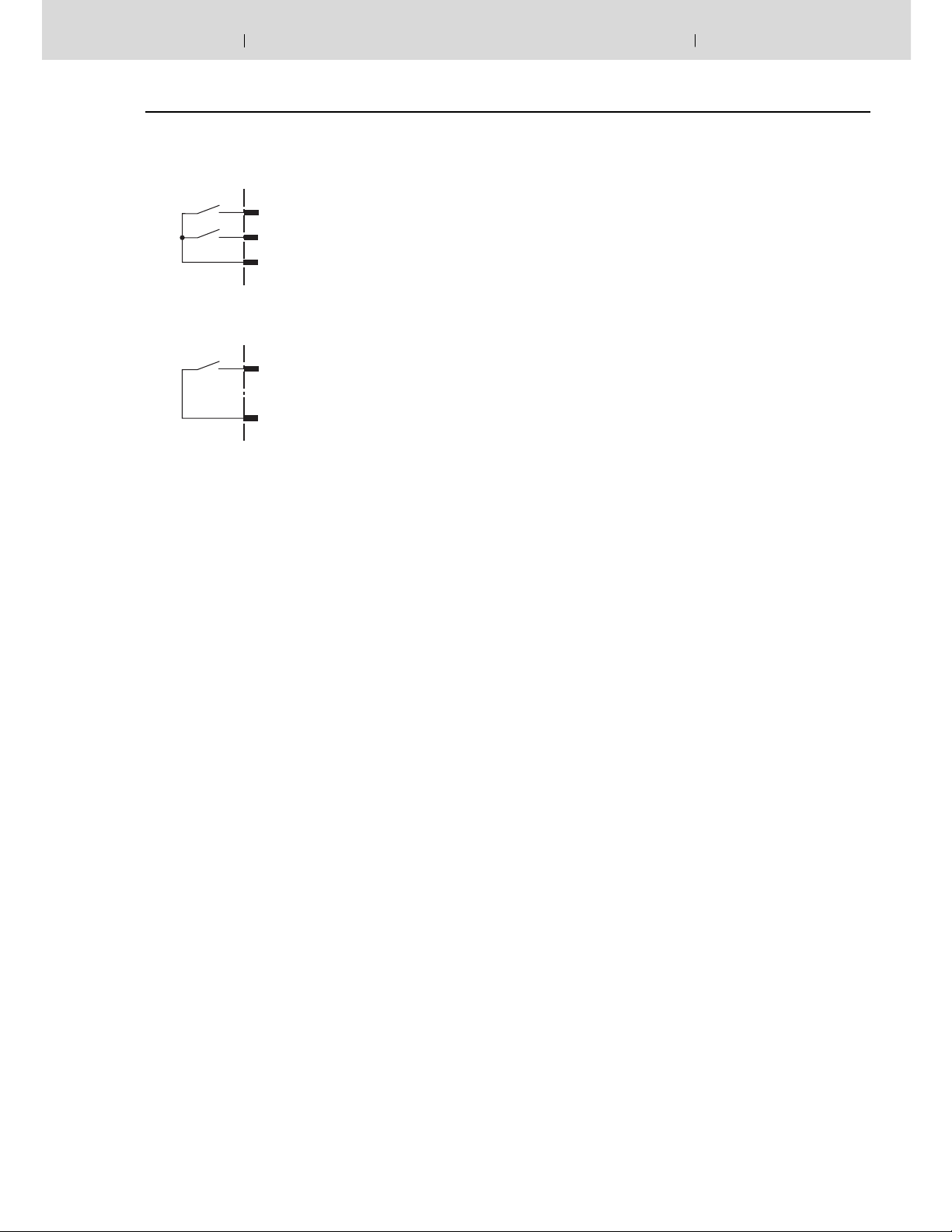
The following is valid for type VT-VSPA1-1: The up and down
ramp times can be set separately to their minimum value (approx. 30 ms) with the help of the external contacts “ramp up/
down OFF”.
The following is valid for type VT-VSPA1K-1: The up and down
ramp times can be set collectively to their minimum value (approx. 30 ms) with the help of the external contact “ramp OFF”.
2)
it can be confi gured as cur-
0 to +10 V / 4 to 20 mA
0 to 20 mA
0V reference potential
28(ac)
u (i)
30(ac)
Additions to the pin designations in brackets are only valid
for type VT-VSPA1-1.
u
RE 30111/09.05
VT-VSPA1-1 and VT-VSPA1K-1
Functional description (continued)
Hydraulics Bosch Rexroth AG
3/12
Ramp "up/down" OFF
VT-VSPA1-1
2a
2c
Ramp "up" OFF
Ramp "down" OFF
4ac
VT-VSPA1K-1
2
Ramp OFF
4
The output signal of ramp generator [4] is fed as current command value to the summing amplifier [5]. Here, a command value of 100 % corresponds to a voltage of +6 V.
Summing amplifi er [5] adds the output signals of the char ac ter is tic curve generators [6 or 7] to the command value (can
be se lect ed by means of DIL switches
2)
depending on the
valve to be controlled). The current command value can also be
fi ltered through a low-pass fi lter that can be cut in. Current output stage [9] is controlled via current regulator [8]. In addition,
the current regulator mod u lates the current command value
with clock-pulse encoder signal [10] (the frequency can be programmed with the help of DIL switches
2)
). The clocked actual
current value acts in the solenoid of the valve like a constant
current with overlaid dither signal. Type VT-VSPA1-1 is pro vid ed with measuring sockets for the internal command value
and the actual value.
The following is valid for the command value: +6 V 100 %
The following is valid for the actual value: 1 mV 1 mA
The signal "ready for operation" is output and LED "H2" on the
front panel (with VSPA1-1) or LED "H2" (with VSPA1K-1) is lit,
when:
– The solenoid cables are not short-circuited and the output
stage is not overloaded,
– a command value is applied (cable break detection),
– there is no cable break present on the solenoid cable.
1)
Reference potential for command value 1 is M0 (measuring
zero).
2)
For
DIL switch settings, see "adjustment elements" on page 8
[ ] … Cross-reference to block circuit diagrams on pages 4
and 5
4/12 Bosch Rexroth AG Hydraulics
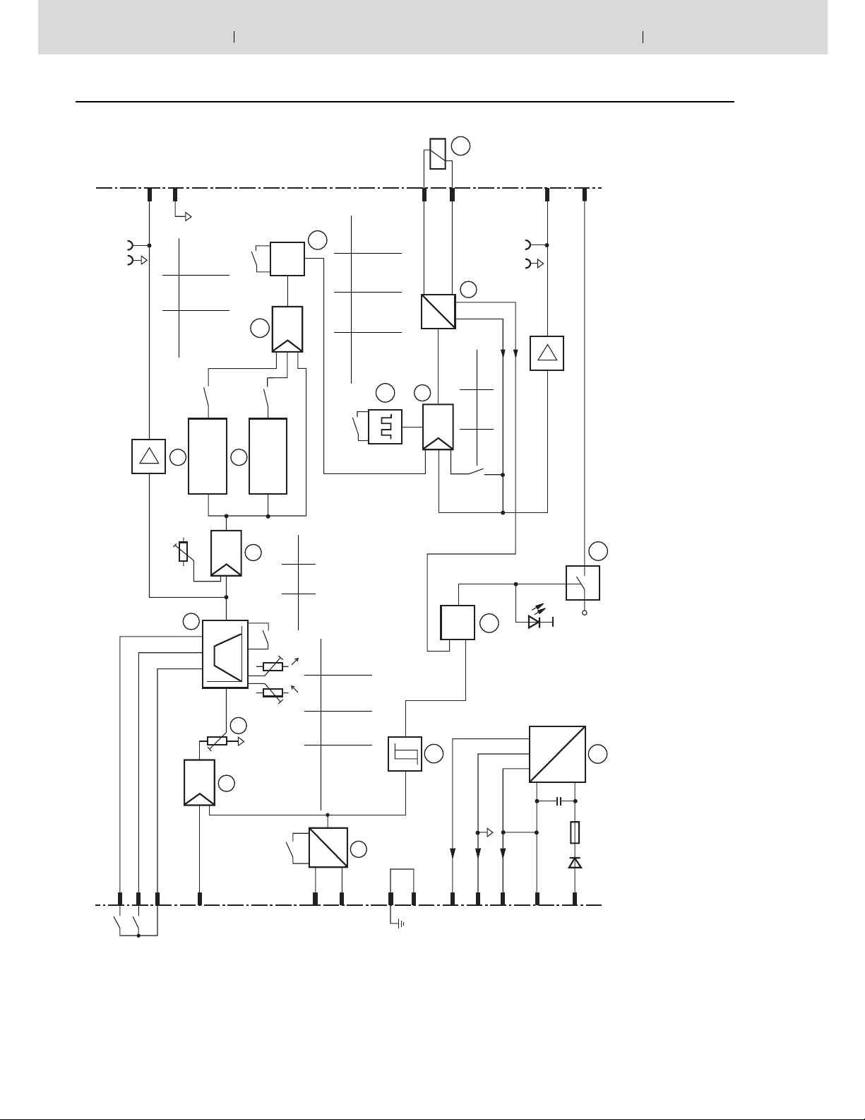
Block circuit diagram / pin assignment: VT-VSPA1-1
Comm. value 0 to 6 V
32ac
14ac
22ac
VT-VSPA1-1 and VT-VSPA1K-1
11
Act. current value
1 mV 1 mA
26c
20ac
26a
Ready for operation
RE 30111/09.05
24 V (50 mA)
value "w"
Command
S2.3 S2.4
0 off off
–3dB
f
S1.5
6
Zw (R130)
4
4 Hz on off
2,5 Hz off on
Char. curve 1
Σ
S2.3 / S2.4
I
15
S1.6
7
Char. curve 2
5
Soll
S1.4
⬃
Σ
S1.4 on off
5 s 1 s
max
t
16
S2.5 S2.6 S2.7
clock
f
100 Hz on on on
200 Hz off on on
S2.5...S2.7
10
300 Hz off off on
"I"
9
i
Actual current value
= Signal “ready for operation“
Additional biasing current adjustment
= Command value attenuation
(0 to 300 mA or 0 to 600 mA)
= Ramp time adjustment
=
u
H2
Gw
t
Zw
(R130)
8
1.6 A 0.8 A
max
I
S1.7 off on
S1.7
Command value monitoring
Monitors14Power supply unit
Low-pass filter
Output “ready for operation“
17
12
13
16
17
&
13
H2
+ 24 V
Note: Measuring zero (M0) is raised by 9 V as against 0V operating voltage!
2a
2c
OFF
Ramp "up" OFF
Ramp "down"
4ac
3
Gw
Σ
2
12ac
Command value 1
t t
S1.1 S1.2 S1.3
Comm. value 2
S1.1...S1.3
28ac
Command value
0…10 V off off off
0…20 mA on on off
4…20 mA on on on
U
1
U/I
8ac
30ac
+10 V
2
4 - 20 mA / 0 - 20 mA
6ac
GND ⊥
12
10ac
+ 9 V (25 mA)
14ac
16ac
M0 (25 mA)
– 9 V (25 mA)
18ac
0 V
DC
Characteristic curve generator 2
Current regulator
Proportional solenoid of valve
Current output stage10Clock-pulse generator
14
DC
2,5 A T
2 x 220 µF
24ac
+ 24 V
8
9
7
Summator
Differential input
1
2; 5; 15
11
1
Max. command value attenuator
Ramp generator
Characteristic curve generator
3
4
6
 Loading...