


RP27PT
BBT
NORTH AMERICA
Bosch Group
www.boschpro.com

Existen restricciones en las
tuberías de fontanería.
Compruebe la fontanería. Utilice
sólo cinta de teflón para sellar las
juntas de las tuberías. Compruebe y
limpie la pantalla del filtro de aire en
el calentador.
Presión de suministro de agua
demasiado baja.
Compruebe que las válvulas de
cierre de entrada están totalmente
abiertas.
Caudal de agua
demasiado bajo
Las válvulas de cierre de salida
tienen un ajuste demasiado
bajo.
Ajuste las válvulas de cierre de
salida según se describe en la
sección "Ajuste del caudal" (véase la
Página 8).
La temperatura
del agua fluctúa
Fluctuación en la presión del
agua o en el caudal
Evite utilizar al mismo tiempo varias
salidas de agua caliente, ya que
esto puede ocasionar fluctuaciones
en la temperatura.
Si el problema no se soluciona
La persona que instaló inicialmente la unidad es la más adecuada para proporcionar
ayuda.
También puede llamar al número de teléfono de llamada gratuita de BBT 800-798-8161. Tenga a
mano esta guía cuando llame.
PowerStream Pro
GARANTÍA LIMITADA DE 10 AÑOS
COBERTURA
APPLIED ENERGY PRODUCTS, A TRAVÉS DE SU DISTRIBUIDOR EN LOS EE.UU., BOSCH WATER
HEATING (en lo sucesivo denominado BBT) garantiza este calentador de agua al propietario
original del mismo y en la ubicación de instalación original contra defectos en los materiales y en la
fabricación durante el período de tiempo indicado a continuación.
PERÍODO DE GARANTÍA
1. Intercambiador de calor: si existen pérdidas o fallos en el intercambiador de calor antes de los diez
(10)
años a partir de la fecha de instalación original del calentador de agua que estén ocasionados
por un defecto en el material o la fabricación, BBT proporcionará al propietario un nuevo calentador
del modelo actual equiparable.
Sin embargo, si el calentador de agua se instala en otra ubicación distinta de una vivienda familiar
individual, esta garantía está limitada a dos (2) años a partir de la fecha de la instalación y
funcionamiento originales.
Nota: La garantía no cubre los daños ocasionados por congelación.
Nota: La garantía no cubre los daños ocasionados por la formación de incrustaciones.
2. Otros componentes que no sean el intercambiador de calor: si otro componente (que no sea el
intercambiador de calor) presenta defectos en el material o la fabricación antes de un (1) año a
partir de la fecha de instalación original del calentador de agua, BBT proporcionará al propietario
nuevos componentes.
Important Safety Instructions
When using this electrical equipment, basic safety precautions should always be
followed, including the following:
1. READ AND FOLLOW ALL INSTRUCTIONS.
2. This appliance must be grounded.
3. Disconnect this product from the electrical supply before cleaning, servicing or removing the
cover.
4. To reduce the risk of injury, close supervision is necessary when the product is used near
children or elderly persons.
5. Warning: Do not install the heater in a location where it may be subject to freezing.
6. Warning: Do not install a check valve or any other type of back flow preventer within ten feet of
the cold water inlet.
7. The electrical installation must conform to current National Electrical Codes.
8. Warning: Do not switch the heater on if you suspect that it may be frozen. Wait until you are
sure that it has completely thawed out.
9. The Powerstream Pro is designed to heat potable cold water for domestic purposes. The
maximum inlet water temperature it can handle is 86 degrees F. Contact Bosch Water Heating
before specifying or installing the appliance in any other application.
10. Additional Canadian safety instructions:
a) As per the Canadian Electrical Code, C22.1-02 Section 26-744, an auxiliary terminal block
must be fitted to the unit before connecting to the electrical supply (Kit Part N° "AE Canada
Kit"). (See Page 6).
b) A green terminal (or a wire connector marked “G,” “GR,” “GROUND” or “GROUNDING”) is
provided within the control. To reduce the risk of electrical shock, connect this terminal or
connector to the grounding terminal of the electrical service of supply panel with a
continuous copper wire in accordance with the Canadian Electrical Code, Part I.
c) This product shall be protected by a Class A ground fault circuit interrupter.
Contents
Using the Powerstream Pro 3
Installing the Powerstream Pro 3
Spare Parts 7
Starting up the Powerstream Pro 7
How the Powerstream Pro works 8
Specifications 9
If you have a problem 10
Warranty 11
SAVE THESE INSTRUCTIONS
Keep this guide in a safe place once your unit has been installed.
You may need to refer to it for general instructions or future maintenance.
2
Using the Powerstream Pro
WARNING
Do not use the unit if you think it may be frozen, as this could result in ser ious damage to the unit. Wait
until you are sure that it has completely thawed out before you switch it on.
•
Check that the power is switched on at the circuit breaker panel.
•
Turn on the hot water faucet FULLY. The hot water temperature can be changed by adjusting the
temperature dial on the bottom surface of the unit. (The dial adjusts the temperature typically
between 95°F and 131°F. The factory sets the temperature dial at the lowest position.)
•
There are internal safety thermal cut-outs which will operate if the unit overheats. If a thermal cutout trips, then it must be reset by a qualified electrician.
• If the unit has been used recently, run the water through for a few seconds to let the temperature
settle down. You may initially get a short burst of very hot water from the unit.
•
If a second outlet connected to the unit is also turned on, the hot water will be shared between the
two.
Installing the Powersteam Pro
WARNING IMPORTANT
Do not install the unit in a room where there Read entire instructions.
is a chance of freezing.
Check the pressure of the main water supply. To operate correctly, the unit needs the following running
pressures : Minimum: 15 psi (1 Bar) Maximum: 150 psi (10 Bar)
Securing the unit to the wall
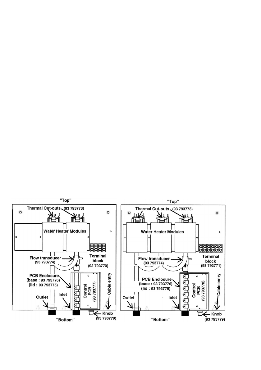
Diagram 1 RP17PT Unit RP27PT Unit
3

• La temperatura del agua de salida también puede variar si se sobrepasa el caudal máximo
(consulte el Gráfico 1) o si cambia el voltaje de entrada.
• Cada módulo calefactor está protegido por un disyuntor térmico electromecánico. Si la temperatura
de uno de los módulos calefactores sube demasiado, el disyuntor se disparará y cortará el
suministro eléctrico en dicho módulo calefactor. Si se dispara el disyuntor, debe ser reajustado por
un técnico de mantenimiento cualificado. Este disyuntor sólo se disparará en circunstancias
excepcionales.
• La unidad RP17PT se suministra con dos voltajes independientes, y la unidad RP27PT se
suministra con tres voltajes independientes. La unidad puede seguir funcionando si se desconecta
o si falla uno de estos voltajes, pero el control de temperatura será deficiente (En Canadá, la unidad
sólo dispone de un suministro de voltaje).
• Según el territorio del país, la temperatura del suministro de agua puede variar entre algo más de
4ºC en invierno y 21ºC en verano, con un promedio de 12,7ºC.
Diagrama 4: Diagrama de conexiones internas para una unidad monofásica RP27PT. (La unidad
RP17PT tiene dos módulos calefactores dos suministros). (En Canadá, durante la instalación se coloca
un bloque de terminales auxiliar).
CUTOUT
L2A
L2C
L2B
L1A
L1B
L1C
Wiring Diagram for AE125, 3 x 240V supply. PowerStar heater.
Thermistor
CUTOUT
CUTOUT
Electronic PCB
Temperature
adjustment
potentiometer
MODULE A
Flow
transducer
Brass inlet manifold and Triac heat sink
For clarity
The positions of
terminals shown
here do not
correspond to
their positions on
the installer
terminal blocks
MODULE B
MODULE C
Especificaciones
Unidad RP17PT
Unidad RP27PT
Suministro de voltaje
2 x 240V CA (Canadá 240V
CA)
3 x 240V CA (Canadá 240V
CA)
Amperaje
2 x 40 A (Canadá 80 A)
3 x 40 A (Canadá 120 A)
Potencia máxima
17,25 kW
26,85kW
Intervalo de control de
temperatura
35°C a 55°C
35°C a 55°C
Intervalo de presión
15 psi hasta 150 psi
15 psi hasta 150 psi
Caudal mínimo
2,26 litros/min
3,02 litros/min
Caudal máximo
Véase el Gráfico 1, Página 8
Véase el Gráfico 1, Página 8
Dimensiones (sin acoplamientos
de agua)
39,3 cm alto x 38,7 cm ancho x
11,4 cm profundo
39,3 cm alto x 38,7 cm ancho x
11,4 cm profundo
Peso (sin agua)
9 kg
10 kg
WARNING
The unit must only be installed in the orientation shown in Diagram 1, i.e., mounted in a vertical position
with the water fittings located at the bottom of the unit.
Under no circumstances should the unit be
mounted differ ently.
•
If being used in a public place, position the unit out of easy reach to discourage vandalism.
•
Mount the unit onto a flat section of wall, well away from any potential splashes of water or spray.
• Position the unit upright with all plumbing and electrical connections at the bottom of the unit.
Mounting on the wall
• Undo the retaining screws on the front cover and take the cover off the unit. Hold the back plate in
position against the wall and mark the four mounting holes.
•
Drill the holes and secure the unit using the four wood screws supplied or an appropriate alternative
method.
Plumbing the unit
WARNING
Do not install a non-return check valve within 10 feet of the inlet. Do not apply heat or solder to
connections or pipes if they are already directly connected to the unit.
Fitting the pipes
• The unit should be connected directly to the main cold water supply and not to pre-heated water.
(The inlet water temperature must not be greater than 86°F.) The unit should be installed with shutoff valves on both the inlet and outlet connections.
• It is recommended that you use ¾ inch or ½ inch copper or high-pressure flex connections.
•
Use Teflon tape for sealing pipe threads. Do NOT use pipe dope.
•
Remember to keep the hot water pipe runs as short as possible.
• After the unit has been plumbed, and before you wire it, flush it with water to remove any debris or
loose particles. Failure to do so may make the unit inoperable.
Connecting the unit to the pipes
• The inlet and outlet connections are clearly marked on the unit. They each have a ¾ inch NPT
connector.
• Install a ball valve in the cold water line. This valve can be used to turn off th e water supply to the
unit if it needs servicing, or to reduce the water flow if it is too high.
DISCLAIMER
As a condition of installing this product in the Commonwealth of Massachusetts a pressure relief valve
shall be installed on the cold water side, by a licensed plumber MGL 142 Section 19 Approval number:
P1-09-25
Wiring to the unit in the United States of America
WARNING
The unit must be installed by a qualified electrician, in accordance with the current version of the National
Electrical Code. The unit must be grounded.
4
 Loading...