


RA1054
IMPORTANT: IMPORTANT : IMPORTANTE:
Read Before Using Lire avant usage Leer antes de usar
For English Version Version française Versión en español
See page 2 Voir page 6 Ver la página 10
Operating/Safety Instructions
Consignes de fonctionnement/sécurité
Instrucciones de funcionamiento y seguridad
1-877-BOSCH99 (1-877-267-2499) www.boschtools.com
Call Toll Free for
Consumer Information
& Service Locations
Pour obtenir des informations
et les adresses de nos centres
de service après-vente,
appelez ce numéro gratuit
Llame gratis para
obtener información
para el consumidor y
ubicaciones de servicio
RA1054
BM 2610998756 09-11:BM 2610998756 09-11 9/22/11 8:03 AM Page 1
-2-
Read and und e r s t a n d
these instructions and tool
manual for use of these accessories.
Disconnect the plug from
the power source before
making any adjustm e n t s , ch a n g i n g
accessories, or storing the tool. Such
preventive safety measures reduce the risk
of starting the tool accidentally.
ASSEMBLING FOR USE AS AN
EDGE GUIDE
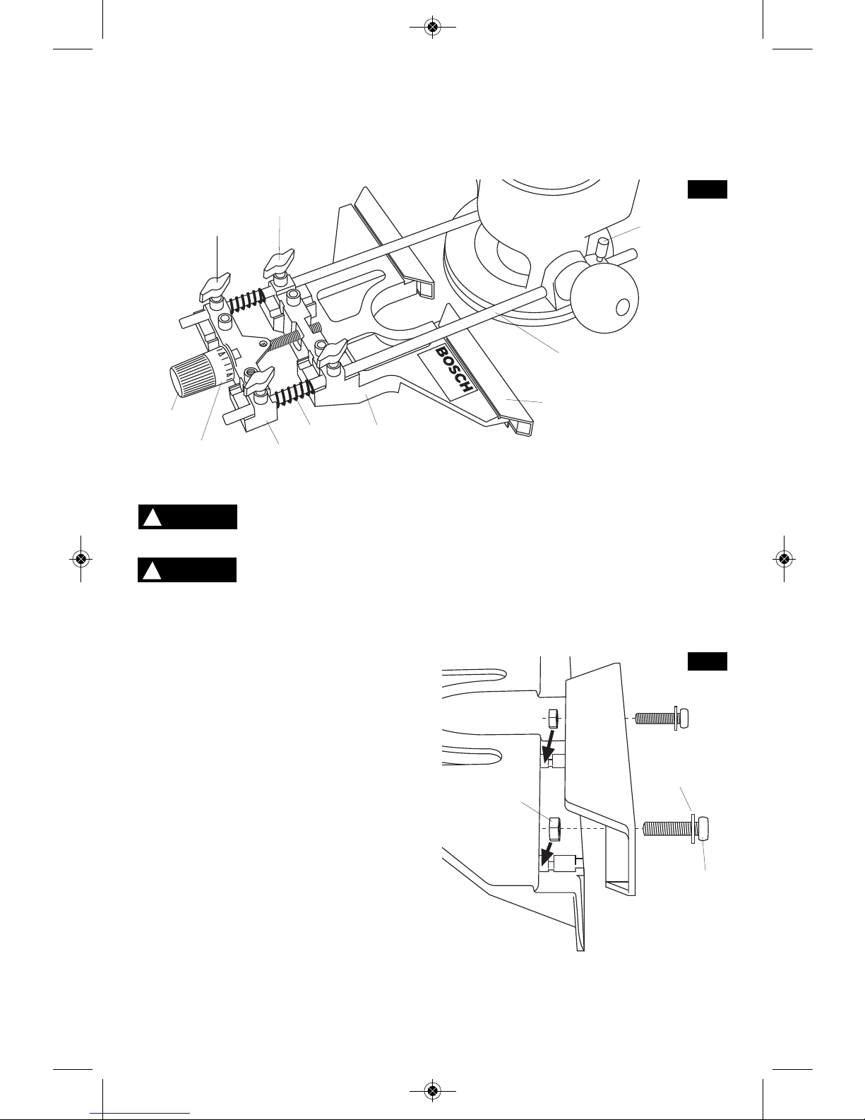
To assemble the Deluxe Router Guide: (Fig. 1)
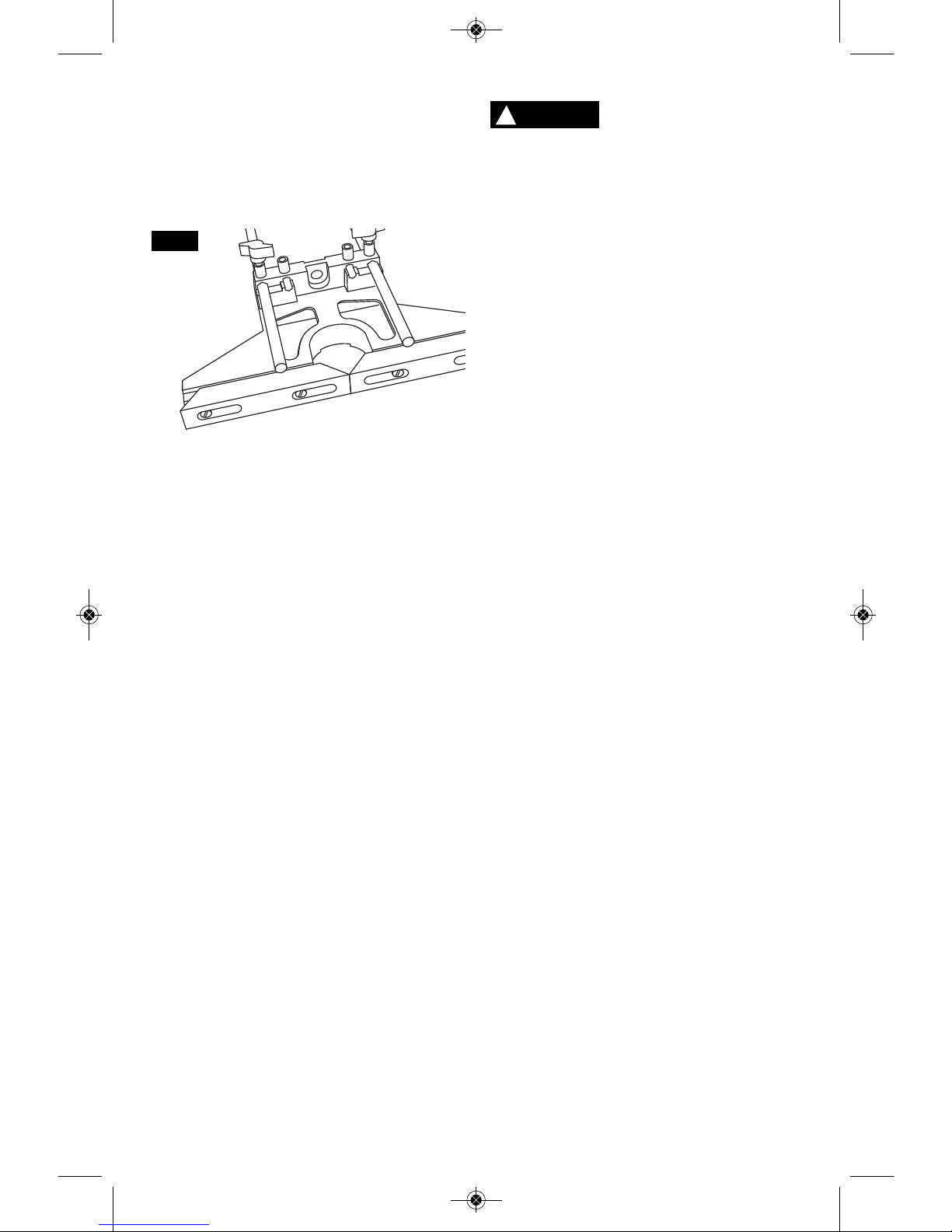
1. Attach the screws (A), washers (B) and nuts
(C) to the guide plates (D) as shown (Fig. 2).
Note: See “Attaching the Dust Extraction
Hood”, on page 2, if you want to attach the
dust extraction hood.
2. Insert the assembled guide plates (D) into
the top of the guide base (E) and tighten.
3. Insert guide rods (F) into the outer holes of
guide base (E).
4. Tighten rods in place with front wing knobs
(G).
5. Place springs (H) over the ends of the rods.
6. Attach rear wing knobs (I) to fine adjustment
guide (J) and slide it over the rods.
7. Screw fine adjustment knob (K), spacer (not
shown) and indicator (L) through fine adjust
guide (J) and into guide base (E). While
assembling, the fine adjustment knob (K)
should be tightened to the point that the
springs H are slightly compressed between the
fine adjust base (J) and the guide base (E).
8. Tighten rear wing knobs (I).
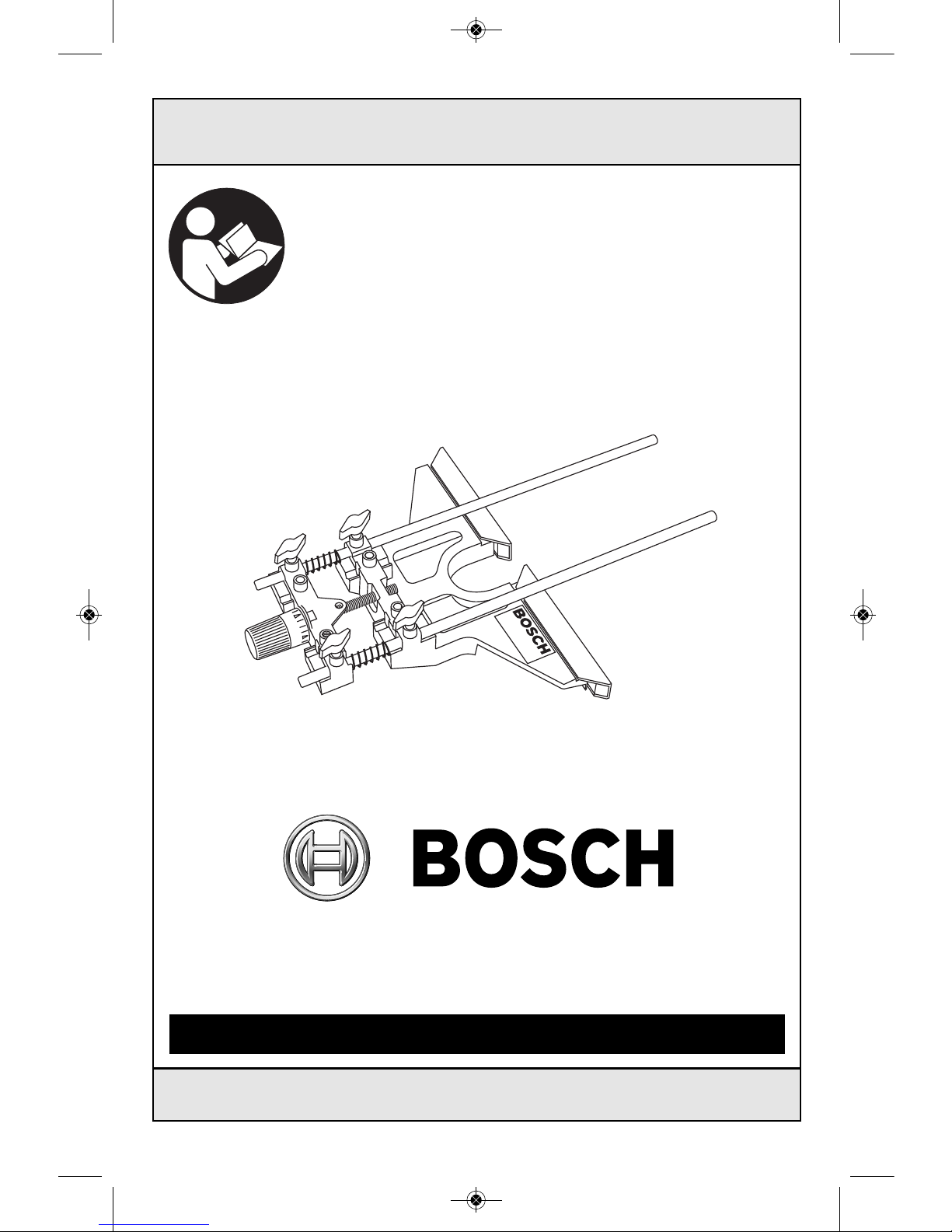
RA1054 BOSCH DELUXE ROUTER GUIDE
For use with Bosch 1613, 1615, 1617/18, 1619, and MR23EVS Series routers
J
F
A
B
D
E
C
K
L
H
E
G
I
FIG. 1
D
N
WARNING
!
FIG. 2
WARNING
!
BM 2610998756 09-11:BM 2610998756 09-11 9/22/11 8:03 AM Page 2
-3-
Do not overreach. Keep
proper footing and balance
at all times. This enables better control of the
power tool in unexpected situations.
Always maintain control of
tool power switch. Some
cutting applications require repositioning of
your hands. Always ensure that one hand is
in control of the power switch.
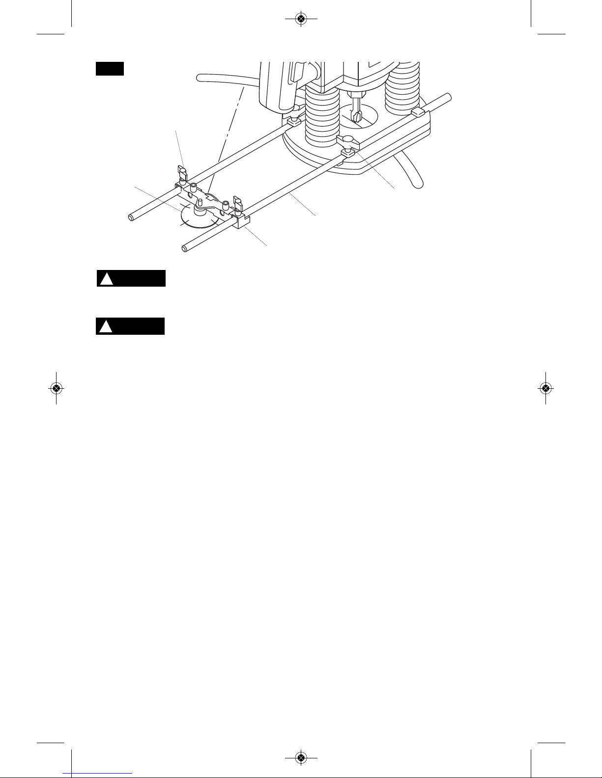
ASSEMBLY FOR USE AS
A CIRCLE GUIDE
To reassemble the deluxe router guide for use
as a circle guide (or arc guide), follow these
steps: (Fig. 3)
1. Loosen rear w i n g knobs (I) and fine
adjustment knob (K), spacer, and indicator
(L) and remove these parts from guide rods
(F).
2. Remove springs (H) from guide rods.
3. Loosen front wing knobs (G) and guide
base (E) and remove from the guide rods.
4. Reinstall fine adjustment guide (J) onto
guide rods (F) rotated 180 degrees from
normal position so that circle guide hole
faces away from the router.
5. Insert guide rods (F) into router base. For
maximum stability, make sure each rod
goes through both holes and protrudes out
the other side of the router base. (At a
minimum, the rods must be inserted far
enough into the router base that they are
both su pported from below at a point
beyond the fastener on the router.)
6. Securely fasten the router to the rods by
tigh t e n i n g the thumbscrews (N).
(Depending on the router model, another
set of wing knobs (O) may be used instead
of the knurled thumbscrews.) The largest
circles and arcs can be made when the
guide rods enter the side of the router
where the thumbscrews (or wing knobs)
are located.
7. Mark the workpiece at the center of the
desired circle.
8. Using the centering slots on the edge of the
pivot plate (P), center the pivot plate on the
center mark and attach to the workpiece
with several strips of strong tape placed
over the pivot plate in a crisscross pattern.
9. Place fine adjustment guide (J) on pivot
plate (P) so that the hole in guide (J) fits
over the steel pin.
10.Adjust the position of the rods and router as
necessary to achieve the desired radius of
the circle or arc, then securely tighten wing
knobs (I).
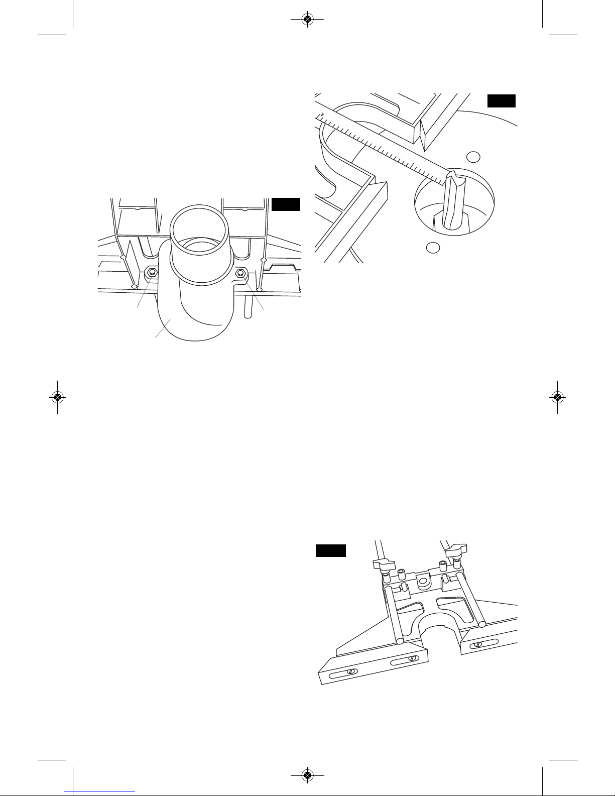
ATTACHING THE DUST
EXTRACTION HOOD
To attach the dust extraction hood (M): (Fig. 4)
1. Remove the two guide pl a t e s (D) by
loosening the four screws and lifting the two
guide plate assemblies off the top of the
guide base.
2. Remove the nuts (C) from the two center
screws.
3. Reattach the guide plates using only their
outside screws.
4. Insert the nuts (C) into the hex cavities in the
dust extraction hood.
F
IG. 3
J
P
I
F
O
WARNING
!
WARNING
!
BM 2610998756 09-11:BM 2610998756 09-11 9/22/11 8:03 AM Page 3
-4-
5
. Move the hood into place beneath the guide
assembly.
6. Insert the two center screws into the guide
assembly and screw into the nuts in the
hood.
The dust extraction hood is sized to accept
35mm vacuum hoses. Also included is an
adapter that will connect the hood to 1-1/4” and
1-1/2” vacuum hoses. Do not use this hood at
the same time you are using any other dust
extraction hood with the router.
ATTACHING THE GUIDE
TO THE ROUTER
1. Insert guide rods F into router base. For
maximum stability, make sure each rod goes
through both holes and protrudes out the
other side of the router base. (At a minimum,
the rods must be inserted far enough into
the router base that they are both supported
fro m below at a po i n t beyond the tw o
knurled thumbscrews (N).)
2. Securely fasten the router to the rods by
tightening the thumbscrews N. (Depending on
the router model, another set of wing knobs
(O) may be used instead of the knurled
thumbscrews.) (Fig. 1 or 3.)
ADJUSTING THE ROUTER
GUIDE POSITION
The router may be positioned either directly
over the guide plates for edge forming
operations or for the creation of slots near the
workpiece edge or beyond the guide plates for
creating slots away from the workpiece edge.
For initial adjustment, slide the router guide
assembly along the rods to the approximate
desired position and securely tighten the rear
set of wing knobs (I). (Fig. 1)
To determine the distance between the bit and
the face plates, place a ruler in the recess in
the bottom of the guide, and measure the
d
istance from the face of the guide plates to
the outermost edge of the router bit. (Fig. 5)
For fine adjustment:
1. Without moving the fine adjustment knob,
move the fine adjustment indicator (L) so
that the ‘0’ position aligns with the indicator
on the fine adjustment guide (J). This
makes it easier to precisely move the guide
in or out by the desired amount.
2. Loosen the front wing knobs (G).
3. To move the router in towards router guide,
turn fine adjustment knob (K) clockwise
(when viewed from back of the router guide)
To move router away from router guide, turn
it counterclockwise. The total travel per
revolution of the knob is 5/64" or 2 mm.
4. When the guide is in the desired location,
securely tighten wing knobs (G).
ADJUSTING THE GUIDE PLATES
Moving the guide plates (D) to their outermost
position extends the overall length of the guide
surface and provides added stability on long
workpieces. (Fig. 6)
FIG. 6
GUIDE PLATES OPENED
1
2
3
FIG. 5
FIG. 4
M
C
C
BM 2610998756 09-11:BM 2610998756 09-11 9/22/11 8:03 AM Page 4
Moving the guide plates (D) inward for edgeforming reduces the gap between the guide
plates and the router bit and provides close-in
support. This is especially helpful when routing
very short workpieces and at the end of any
workpiece. It also reduces the possibility of
t
ear out on the workpiece. (Fig. 7)
The RA1054 can also be used to guide a
router along convex curves. When used in this
way, it is best to fasten the guide plates at their
outer-most positions, then adjust the location
of the router on the rods so that the bit is
positioned to make the desired cut.
The guide plate screws should be tightened to
secure guide plates in the desired location.
Guide plates (D) (and dust
extraction hood, if used)
must clear the router bit by at least 1/8" (3
mm) in all directions.
O
PERATING INSTRUCTIONS
Once the router guide is assembled, attached
and adjusted, it is ready for use.
The router should be fed from left to right with
steady feed pressure
When guiding along straight edges, the guide
plates should be kept in contact with the edge
of the workpiece at all times.
When guiding along convex curves, the two
inner edges of the guide plates should be held
against the workpiece at all times.
USE OF CIRCLE CUIDE
Follow the normal procedure for using the
router.
• When a clean round opening in the
workpiece is desired, the smoothest surface
for the opening will be achieved by moving the
router in a clockwise direction.
• When making a round workpiece such as a
small tabletop, the smoothest surface for the
round workpiece will be achieved by moving
the router in a counter-clockwise direction.
-5-
GUIDE PLATES CLOSED
WARNING
!
FIG. 7
BM 2610998756 09-11:BM 2610998756 09-11 9/22/11 8:03 AM Page 5
 Loading...