


REXROTH VT-HDT
VT-HDT Box
Test device for proportional valves with
integrated electronics (OBE)
Type VT-HDT-1-2X Operating Manual
The test device is suitable for the controlling and functional testing of proportional valves with integrated
electronics (OBE) with an operating voltage of +24V.
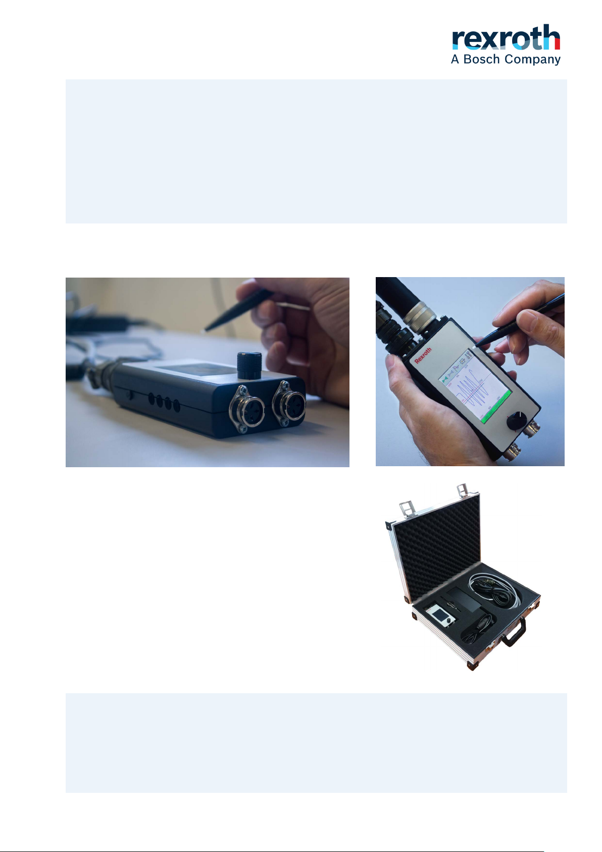
Test device VT-HDT-1-2X Test device VT-HDT-1-2X
Features
▶ The test device simplify the commissioning and troubleshooting
of hydraulic systems with proportional valves with integrated
electronics
▶ Simple and intuitive operation via touchscreen
▶ Screens for digital or analog display
▶ Automatic valve detection
▶ Setpoint generator with interval function
▶ Ramp function
▶ Potentiometer operation
▶ Dead man´s handle
▶ 2 outputs for switching valves
▶ Sockets for external measurements
▶ Service case with test device, 24 V power supply, OBE connection
cable and 2 cables for switching valves (see ordering information)
Service case VT-HDTSY-1-2X
Notice:
The test device might only be used by persons who are familiar with the device, the valve, and the hydraulic
system. With the corresponding setting, the control signals coming from the system are going to be ignored.
If control-side safety regulations are provided, they are thereby rendered inoperable.
The use of the device on running systems is always at your own risk!
No liability will be accepted for damage caused by incorrect operation!
Bosch Rexroth GmbH Austria V1.08 / 2019-01 Page 1
Pos. Designation
Type
Part No.
1
Test device VT-HDT Box
VT-HDT-1-2X
R996037000
2
OBE-Connection cable 6-pol. 3m
VT-HDTK-1-2X
R996037001
3
Power supply unit 120W, 90-264VAC/+24VDC/5A
VT-HDTNT-5-2X
R996025391
4
Switching valve cable 3m
VT-HDTSK-1-2X
R996037002
5
Service case (consisting of: Pos.1, 2, 3)
VT-HDTSY-1-2X/1-1-0-1-0
R996036999
6
Service case compl. incl. 2 switching valve cables
VT-HDTSY-1-2X/1-1-2-1-0
R996043985
Warning
Content
Features . ........................................................................................................................................ 1
Ordering code ................................................................................................................................. 2
Test device type VT-HDT-1-2X: ..................................................................................................... 3
▶ Operation modes and function ........................................................................................... 4
▶ Screens............................................................................................................................... 7
▶ Device view......................................................................................................................... 9
▶ Connections ........................................................................................................................ 9
▶ Technical data .................................................................................................................... 10
Service case VT-HDTSY-1-2X ........................................................................................................ 11
Power supply unit VT-HDTNT-5-2X ................................................................................................ 11
OBE-connection cable VT-HDTK-1-2X ........................................................................................... 12
Switching valve cable VT-HDTSK-1-2X .......................................................................................... 12
Environmental protection and disposal ........................................................................................... 13
Read this documentation completely, and in particular the safety and warning instructions, before you
work with the product.
Ordering code:
Usage is only granted to qualified personnel!
Only for the intended use!
The correct connection and the correct settings on the device must be ensured!
In particular, the use of the device on running machines poses risks for material
and human, which only the operator has to estimate!
The device must be handled with care, especially soiling, moisture, condensation and mechanical loads should be avoided!
Use in potentially explosive environments is prohibited!
Bosch Rexroth GmbH Austria V1.08 / 2019-01 Page 2
Warning
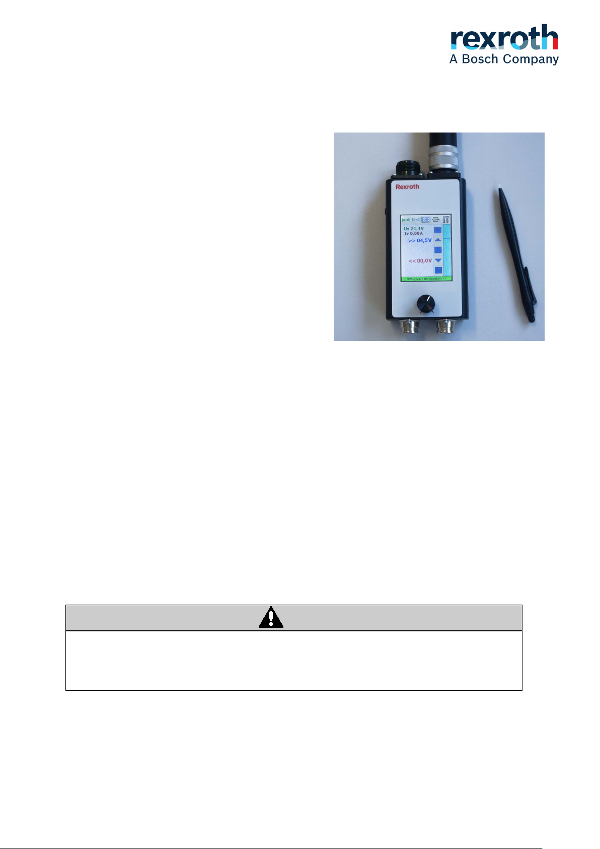
Test device type VT-HDT-1-2X
Approbiate use:
The test device is intended for checking the function
of proportional valves with OnBoardElectronic (OBE)
with an operating voltage of +24V
These can be directional valves, throttles, pressure
limiting, proportional valves, etc.
The power supply is done either by power supply unit
+24V (VT-HDTNT) or valve cable on site.
The operating mode "Simulator mode" may only be
used, when the valve , which is going to get tested, is
removed (from the machine separated) or appropriate
security measures have been implemented.
Touchscreen: Type VT-HDT-1-2X
The brightly lit TFT touchscreen is easy to read and
intuitive to use.
The resistive touchscreen is resistant to dirt.
General conditions:
The valve supply (24V) is applied to terminals A (+) and B (-).
The setpoint is applied to terminals D (+) and E (-).
The actual value is applied to the terminals F (+) and C (-).
Exception: Setting in the screen RANGE: 24V-> C, F: B (E)
With this setting, 24V are switched to terminal C (for example: Enable).
The actual value is measured in this case at the terminals F (+) and B (-).
For valves, which provide the actual value at the terminals F (+) and E (-), please contact the manufacturer.
The range setting '24V-> C, F: B (E)' causes 24V to reach terminal C.
This can lead to defects at unsuitable valves or cause machinery movement.
The user will be informed by an additional security prompt.
Bosch Rexroth GmbH Austria V1.08 / 2019-01 Page 3
Warning
Warning
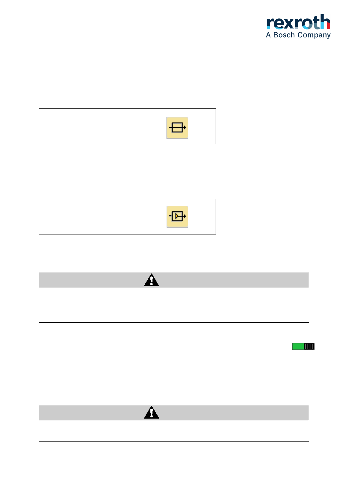
Operating modes and functions:
External mode:
The signals from the valve input connector are looped through to the valve output connector. The signals
are measured internally and displayed. A setpoint specification is not possible.
External mode is activ
Simulator mode:
The setpoint is generated internally and output to the valve output connector.
Depending on the preselection, setpoint can be set via potentiometer or touch screen.
The output setpoint and the actual value from the valve are measured and displayed.
Simulator mode activ
Burden resistance at mA ranges:
In external mode, the current for actual value flows over the burden resistance of the ext. control.
In simulator mode over the internal burden resistance of the test device.
Only use the operating mode "simulator mode" if the valve, which is going to get tested, has
been removed (disconnected from the machine) or if appropriate safety measures have been
implemented by the operator!
Dead man´s handle: Deadman activ
When working on systems, this operating mode is required.
A setpoint specification is only possible, when the button is pressed.
If the button released, the setpoint goes to 0%; The switching valves are not switched off, when the button is
released.
When the button is pressed again, the setpoint remains at 0%; A setpoint must be specified again.
The status of the dead man´s handle is displayed at the 'Range bar' (red / green)
The dead man´s handle is not a safety device in sense of machine safety rules!
Bosch Rexroth GmbH Austria V1.08 / 2019-01 Page 4

Attention
Operation with potentiometer: Potentiometer activ
The valve setpoint is changeable with a potentiometer. The touch functions are not active.
The center position of the potentiometer always equals 0% (no movement)
i.e.: Middle position corresponds to 12mA at range 4 .. (12) .. 20mA
Center position corresponds to 0V at range (0) .. +10V (left side of adjustmant range not active)
When potentiometer operation is activated, the output setpoint is 0%, independent of the current position.
Only after the potentiometer has been turned to 'zero position' once, the potentiometer is active.
('Range bar' changes from 'Orange' to 'Green')
This applies:
- when power up the test device
- when selecting the operation with potentiometer
- when working with dead man´s handle
Sockets for external measurements: Measuring sockets activ
The setpoint and the actual value of the valve can be recorded (external measuring devices, data loggers).
The measured values are only available at the sockets if this setting is activated.
The sockets are wired internally, according to the range selected (V or mA - no jumper is needed at the measuring sockets).
The measuring sockets can also be used:
- for device calibration
- for controlling a frequency converter or other devices
(in the V range without special adapter cable)
Only devices with potential-free measuring inputs may be connected!
Analog curves: 4 curves activ
It can be selected whether only the setpoint and the actual value are shown in screen 'ANALOG' or
additionally 'Uv' and 'Iv'.
Bosch Rexroth GmbH Austria V1.08 / 2019-01 Page 5
 Loading...