


IMPORTANT: |
IMPORTANTE: |
Read Before Using |
Leer antes de usar |
Operating/Safety Instructions
Instrucciones de funcionamiento y seguridad
RA1180
Consumer Information Información para el consumidor
Toll Free Number: Número de teléfono gratuito: 1-877-BOSCH99 (1-877-267-2499) http://www.boschtools.com
For English |
¿Habla español? |
See page 2 |
Ver página 32 |
|
|

Power Tool Safety Rules
 Read and understand the tool manual and these instructions for the use of this table with your router. Failure to follow all instructions listed below may result in serious personal injury.
SAVE THESE INSTRUCTIONS
Work Area |
Personal Safety |
1.Keep your work area clean and well lit. Cluttered benches and dark areas invite accidents.
2.Do not operate power tools in explosive atmospheres, such as in the presence of flammable liquids, gases, or dust. Power tools create sparks which may ignite the dust or fumes.
3.Keep bystanders, children, and visitors away while operating a power tool. Distractions can cause you to lose control.
Electrical Safety
1.Double Insulated tools are equipped with a polarized plug (one blade is wider than the other.) This plug will fit in a polarized outlet only one way. If the plug does not fit fully in the outlet, reverse the plug. If it still does not fit, contact a qualified
electrician to install a polarized outlet. Do not change the plug in any way. Double Insulation 


 eliminates the need for the three wire grounded power cord and grounded power supply system. Before plugging in the tool, be certain the outlet voltage supplied is within the voltage marked on the nameplate. Do not use “AC only” rated tools
with a DC power supply.
2.Avoid body contact with grounded surfaces such as pipes, radiators, ranges and refrigerators. There is an increased risk of electric shock if your body is grounded. If operating the power tool in damp locations is unavoidable, a Ground Fault Circuit Interrupter must be used to supply the power to your tool. Electrician’s rubber gloves and footwear will further enhance your personal safety.
3.Don’t expose power tools to rain or wet conditions.
Water entering a power tool will increase the risk of electric shock.
4.Do not abuse the cord. Never use the cord to carry the tools or pull the plug from an outlet. Keep cord away from heat, oil, sharp edges or moving parts.
Replace damaged cords immediately. Damaged cords increase the risk of electric shock.
5.When operating a power tool outside, use an outdoor extension cord marked “W-A” or “W.”
These cords are rated for outdoor use and reduce the risk of electric shock. Refer to “Important Infornation about Extension Cords” on page 4.
1.Stay alert, watch what you are doing and use common sense when operating a power tool.
Do not use tool while tired or under the influence of drugs, alcohol, or medication. A moment of inattention while operating power tools may result in serious personal injury.
2.Keep guards in place. Maintain the guards in working order and in proper adjustment and alignment.
3.Avoid accidental starting. Be sure switch is “OFF” before plugging in. Carrying tools with your finger on the switch or plugging in tools that have the switch “ON” invites accidents.
4.Remove adjusting keys or wrenches before turning the tool “ON”. A wrench or a key that is left attached to a rotating part of the tool may result in personal injury.
5.Do not overreach. Keep proper footing and balance at all times. Proper footing and balance enables better control of the tool in unexpected situations.
6.Use safety goggles (head protection). Wear safety goggles (must comply with ANSI Standard Z87.1) at all times. Wear a non-slip footwear and a hard hat, if appropriate. Also, use face or dust mask if cutting operation is dusty, and ear protectors (plugs or muffs) during extended periods of operation.
Tool Use and Care
1.Use clamps or other practical way to secure and support the workpiece to a stable platform.
Holding the work by hand or against your body is unstable and may lead to loss of control.
2.Do not force tool. Use the correct tool for your application. The correct tool will do the job better and safer at the rate for which it is designed.
3.Do not use tool if switch does not turn it “ON” or “OFF”. Any tool that cannot be controlled with the switch is dangerous and must be repaired.
4.Disconnect the plug from the power source before making any adjustments, changing accessories, or storing the tool. Such preventive safety measures reduce the risk of starting the tool accidentally.
5.Keep guards in place. Maintain the guards in working order and in proper adjustment and alignment.
6.Store idle tools out of reach of children and other untrained persons. Tools are dangerous in the hands of untrained users.
2

7.Never leave tools running unattended. Turn the power OFF. DO NOT leave tool until it comes to a complete stop.
8.Maintain tools with care. Keep cutting tools
sharp and clean. Properly maintained tools, with sharp cutting edges are less likely to bind and are easier to control. Any alteration or modification is a misuse and may result in a dangerous condition.
9.Check for damaged guards or parts, misalignment or binding of moving parts, breakage of parts, and any other condition that may affect the tools operation.
If damaged, have the tool properly repaired or replaced before using. Many accidents are caused by poorly maintained tools. Develop a periodic maintenance schedule for your tool.
10.Use only accessories that are recommended by the manufacturer for your model. Accessories that may be suitable for one tool, may become hazardous when used on another tool.
Service
1.Tool service must be performed only by qualified repair personnel. Service or maintenance performed by unqualified personnel could result in a risk of injury. For example: internal wires may be misplaced or pinched, safety guard return springs may be improperly mounted.
2.When servicing a tool, use only identical replacement parts. Follow instructions in the Maintenance section of this manual. Use of unauthorized parts or failure to follow Maintenance Instructions may create a risk of electric shock or injury. Certain cleaning agents such as gasoline, carbon tetrachloride, ammonia, etc. may damage plastic parts.
Additional Warnings for Router Tables
1.Read and understand table and router manual and accessory warnings. Failure to follow all instructions and warnings may result in serious personal injury.
2.Fully assemble and tighten all fasteners required for this table and for mounting the router to the plate. Do not use the router table until all assembly and installation steps have been completed. Check the stand and the router to make sure fasteners are still tight before each use. A loose stand is unstable and may shift in use.
3.Make certain the router is not plugged into a power outlet when installing into the table, removing from table, making adjustments or changing accessories. Router could accidentally start.
4.Do not plug router motor power cord into standard wall outlet. It must be plugged into the router table switch. Power tool switches and controls need to be within your reach in emergency situations.
5.Before operating make sure the entire unit (table with router installed) is placed on and secured to a solid, flat, level surface and will not tip. Use of auxiliary in-feed and out-feed supports is necessary for long or wide workpieces.
Long workpieces without adequate support can flip off the table or cause the table to tip over.
6.Be certain router motor is fully and securely clamped in the router base. Periodically check
the base fastener clamping tightness. Router motor can vibrate loose from the base during use and fall from table.
7.Do not use the router table without the overhead guard or auxiliary bit guard. Remove all dust, chips, and any other foreign particles that can affect its function. Adjust the guard height so that it clears the router bit and the workpiece. The guard will aid in keeping hands from unintended contact with
rotating bit.
8.Never place your fingers near a spinning bit or under the guard when router is plugged in. Never hold the workpiece on the out-feed side of bit.
Pressing the workpiece against the out-feed side of the fence may cause material binding and possible kickback pulling hand back into bit.
9.Guide workpiece by fence or pin to maintain control of workpiece. Do not place material between router bit and fence while routing the edge or between piloted router bit and starter pin. This placement will cause the material to become wedged. making kickback possible.
10.Routers are intended for working with wood, woodlike products and plastic or laminates, not for cutting or shaping metals. Be sure workpiece does not contain nails, etc. Cutting nails may cause loss of control.
11.Do not use bits that have a cutting diameter that exceeds clearance hole in table top insert. Bit could contact insert ring, throwing fragments.
12.Install bit in accordance with instructions in router manual and securely clamp the router bit in the collet chuck before making any cuts to avoid bit becoming loose during operation.
13.Never use dull or damaged bits. Sharp bits must be handled with care. Damaged bits can snap during use. Dull bits require more force to push the workpiece, possibly causing the bit to break or the material to kickback.
14.The router table is designed to cut flat, straight and squared materials. Do not cut material that is warped, wobbly or otherwise unstable. If the material is slightly curved but otherwise stable, cut the material with the concave side against the table or fence. Cutting the material with the concave side up or away from table may cause the warped or wobbly material to roll and kick back and cause user to lose control.
15.Never start the tool when the bit is engaged in the material. The bit cutting edge may grab the material causing loss of control of the workpiece.
16.Feed the workpiece against the rotation of the bit. The bit rotates counter-clockwise as viewed from the top of table. Feeding the work in the wrong direction will cause the workpiece to “climb” up on the bit, pulling the workpiece and possibly your hands into the rotating bit.
3
Additional Warnings for Router Tables
17.Use push sticks, vertical and horizontally mounted feather boards (spring sticks) and other jigs to hold down the workpiece. Push sticks, feather boards and jigs eliminate the need to hold the workpiece near the spinning bit.
18.Piloted bits along with the starter pin are used when routing internal and external contours on the workpiece. Use the auxiliary bit guard when shaping material with the starter pin and piloted bits. The starter pin and bearing of the piloted bit assist in maintaining control of the workpiece.
19.Do not use the table as workbench or worksurface. Using it for purposes other than routing may cause damage and make it unsafe to use in routing.
20.Never stand on the table or use as ladder or scaffolding. Table could tip or the cutting tool could be accidentally contacted.
21.Use only Bosch replacement parts. Any others may create a hazard.
Improper Fence Location and Workpiece Feed


 The fence and/or workpiece are improperly located anytime it would result in:
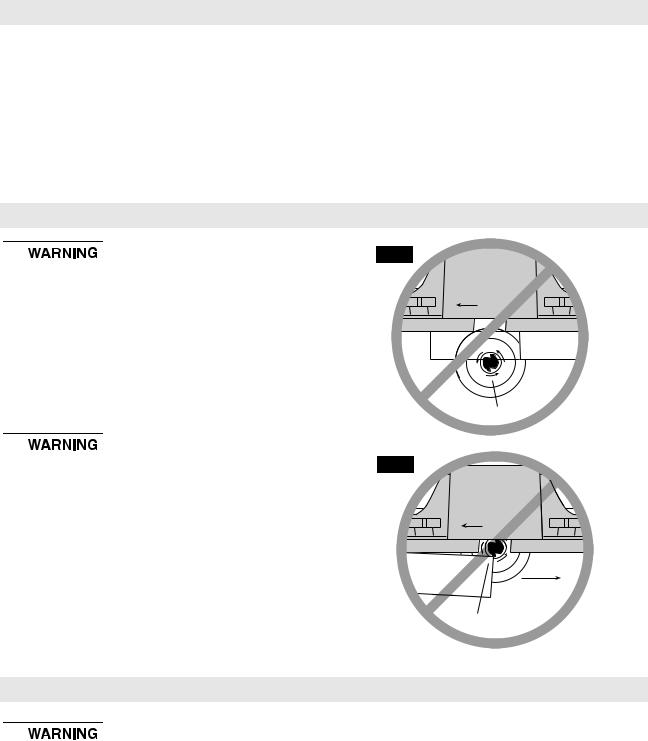
•The front of the bit is exposed during the actual cutting (Fig. A).
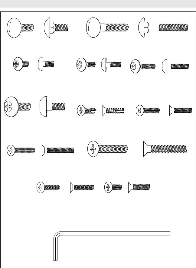
•“Climb-cutting” - The bit must not enter the workpiece in the same direction as the feed direction, which is likely to cause the workpiece to "climb" and may lead to loss of control during operation (Fig. B).
"Fence Traps": One type of improper fence location warrants special attention: "Fence traps" happen when the fence is positioned so far back that front side (power switch side) of the workpiece would be behind the router bit.


 Fence traps are dangerous for two reasons:
•Exposure of the bit on the front side (power switch side) of the workpiece.
•Likeliness of climb cut, which can cause loss of control. Fig. A shows a fence trap.
Do not feed the workpiece from left to right: (Fig. B)
•It would cause climb-cutting.
•It would be difficult to keep the workpiece against the fence faces because the bit rotation would push the workpiece away from the fence.
FIG. A
DIRECTION
OF FEED
WORKPIECE
EXPOSED BIT
FIG. B
CORRECT
DIRECTION
OF FEED
WORKPIECE
INCORRECT
DIRECTION
CLIMB-CUTTING
Important Information About Extension Cords


 If an extension cord is necessary, a cord with adequate size conductors that is capable of carrying the current necessary for your tool must be used. This will prevent excessive voltage drop, loss of power or overheating. Grounded tools must use 3-wire extension cords that have 3-prong plugs and receptacles. NOTE: The smaller the gauge number, the heavier the cord.
RECOMMENDED SIZES OF EXTENSION CORDS 120 VOLT ALTERNATING CURRENT TOOLS
Tool’s |
Cord Size in A.W.G. |
Wire Sizes in mm2 |
|||||||
|
|
|
|
|
|
|
|
||
Ampere |
|
|
|
|
|
|
|
|
|
Cord Length in Feet |
Cord Length in Meters |
||||||||
Rating |
|||||||||
|
25 |
50 |
100 |
150 |
15 |
30 |
60 |
120 |
|
3-6 |
|
|
|
|
|
|
|
|
|
18 |
16 |
16 |
14 |
.75 |
.75 |
1.5 |
2.5 |
||
6-8 |
18 |
16 |
14 |
12 |
.75 |
1.0 |
2.5 |
4.0 |
|
8-10 |
18 |
16 |
14 |
12 |
.75 |
1.0 |
2.5 |
4.0 |
|
10-12 |
16 |
16 |
14 |
12 |
1.0 |
2.5 |
4.0 |
— |
|
12-16 |
14 |
12 |
— |
— |
— |
— |
— |
— |
|
|
|
|
|
|
|
|
|
|
|
4

Symbols
IMPORTANT: Some of the following symbols may be used on your tool. Please study them and learn their meaning. Proper interpretation of these symbols will allow you to operate the tool better and safer.
Symbol |
Name |
Designation/Explanation |
||||||
V |
Volts |
Voltage (potential) |
||||||
A |
Amperes |
Current |
||||||
Hz |
Hertz |
Frequency (cycles per second) |
||||||
W |
Watt |
Power |
||||||
kg |
Kilograms |
Weight |
||||||
min |
Minutes |
Time |
||||||
s |
Seconds |
Time |
||||||
Ø |
|
|
|
|
|
Diameter |
Size of drill bits, grinding wheels, etc. |
|
n0 |
No load speed |
Rotational speed, at no load |
||||||
.../min |
Revolutions or reciprocation |
Revolutions, strokes, surface speed, orbits |
||||||
|
|
|
|
|
|
|
per minute |
etc. per minute |
0 |
|
|
|
|
|
|
Off position |
Zero speed, zero torque... |
1, 2, 3, ... |
Selector settings |
Speed, torque or position settings |
||||||
I, II, III, |
|
Higher number means greater speed |
||||||
0 |
|
|
|
|
|
Infinitely variable selector |
Speed is increasing from 0 setting |
|
|
|
|
|
|
|
|
with off |
|
|
|
|
|
|
|
|
Arrow |
Action in the direction of arrow |
|
|
|
|
|
|
|
||
|
|
|
|
|
|
|
Alternating current |
Type or a characteristic of current |
|
|
|
|
|
|
|
Direct current |
Type or a characteristic of current |
|
|
|
|
|
|
|
||
|
|
|
|
|
|
|
Alternating or direct current |
Type or a characteristic of current |
|
|
|
|
|
|
|
||
|
|
|
|
|
|
|
Class II construction |
Designates Double Insulated Construction tools |
|
|
|
|
|
|
|
||
|
|
|
|
|
|
|
|
|
|
|
|
|
|
|
|
Earthing terminal |
Grounding terminal |
|
|
|
|
|
|
|
||
|
|
|
|
|
|
|
Warning symbol |
Alerts user to warning messages |
|
|
|
|
|
|
|
||
|
|
|
|
|
|
|
||
|
|
|
|
|
|
|
Ni-Cad RBRC seal |
Designates Ni-Cad battery recycling program |
|
|
|
|
|
|
|
|
|
This symbol designates that this tool is listed
by Underwriters Laboratories.
This symbol designates that this tool is listed by the Canadian Standards Association.
This symbol designates that this tool is listed to Canadian Standards by Underwriters Laboratories.
This symbol designates that this tool is listed by Underwriters Laboratories, and listed to Canadian Standards by Underwriters Laboratories.
This symbol designates that this tool complies to NOM Mexican Standards.
5

Parts List
Refer to Parts List below and on pages 7–9.
•


 If ANY of the parts is missing, DO NOT attempt to assemble, install, or use your router table until the missing parts have been found or replaced and your router table has been properly and correctly assembled per this manual.
•For missing parts or technical assistance,
call 1-877-BOSCH99 (877-267-2499).
•In order to simplify handling and to minimize any damage that may occur during shipping, your router table comes unassembled.
•Separate all parts from the packaging materials and check each part against the illustrations and the parts lists on pages 6–9, to make sure that all parts have been included. Do this before discarding any of the packaging material.
|
Key No. |
Description |
|
Quantity |
|
|
A |
ROUTER TABLE ASSEMBLY |
|
|
|
|
1 |
Router Table |
|
1 |
|
|
2 |
Fence Support Bracket |
2 |
|
|
|
3 |
Fence Guide (Black) |
|
2 |
|
|
|
|
|
||
|
4 |
Clamping Knob (Black) |
4 |
|
|
|
|
|
|
||
|
5 |
Router Adapter Plate (Gray) |
1 |
|
|
|
|
|
|
|
|
|
6 |
Guard Bracket |
|
1 |
|
|
|
|
|
|
|
|
7 |
Lower Fence |
|
2 |
|
|
|
|
|
|
|
|
8 |
Upper Fence |
|
1 |
|
|
|
|
|
||
|
9 |
Fence Clamping Knob (Black) |
4 |
|
|
|
10 |
Dust Collector (Black) |
|
1 |
|
|
11 |
Upper Fence End Cap (Right Side, Black) |
1 |
|
|
|
12 |
Upper Fence End Cap (Left Side, Black) |
1 |
|
|
|
|
|
|
||
|
13 |
Lower Fence End Cap (Right Side, Black) |
2 |
|
|
|
|
|
|
||
|
14 |
Lower Fence End Cap (Left Side, Black) |
2 |
|
|
|
|
|
|
|
|
|
15 |
Leg Reinforcement |
|
4 |
|
|
|
|
|
|
|
|
16 |
Table Top Insert w/ 1″ |
Dia. Hole (Red) |
1 |
|
|
17 |
Table Top Insert w/ 2″ |
Dia. Hole (Red) |
1 |
|
|
18 |
Table Top Insert w/ 23⁄4″ Dia. Hole (Red) |
1 |
|
|
|
19 |
Table Leg (Blue) |
|
2 |
|
|
20 |
Fascia/Switch Assembly |
1 |
|
|
|
21 |
Leg Storage Panel (Black) |
1 |
|
|
|
22 |
Leg Cord Wrap Assembly (Black) |
1 |
|
|
|
|
|
|
||
|
23 |
Feather Board (Blue or Gray) |
2 |
|
|
|
|
|
|
|
|
|
24 |
Threaded Support Rod |
|
2 |
|
|
|
|
|
|
|
|
25 |
Router Shield (Guard) |
|
1 |
|
|
|
|
|
||
|
26 |
Knurled Adjustment Nut |
8 |
|
|
|
|
|
|
|
|
|
27 |
Plastic Spacer Washer |
|
2 |
|
|
|
|
|
|
|
|
28 |
Starter Pin |
|
1 |
|
|
29 |
Starter Pin Guard |
|
1 |
|
|
|
MANUALS (NOT SHOWN) |
|
|
|
|
52 |
BOSCH RA1180 Router Table Owner’s Manual |
1 |
|
|
|
53 |
Warranty Card |
|
1 |
|
|
|
|
|
|
|
6

Parts List
|
29 |
|
|
28 |
|
|
5 |
|
|
1 |
|
15 |
|
|
|
21 |
|
22 |
|
|
|
19 |
|
|
19 |
|
Fence |
Feather |
|
37 |
23 |
|
26 |
||
|
||
|
46 |
|
|
26 |
|
|
8 |
|
|
9 |
|
|
Top Inserts |
|
|
18 |
|
12 |
13 |
|
|
||
14 |
|
|
|
7 |

Parts List
|
Key No. |
Description |
Quantity |
|
|
B |
FASTENERS (FOR ROUTER TABLE ASSEMBLY) |
|
|
|
30 |
1/4-20 Weld Nut |
4 |
|
|
31 |
#10-32 KEPS Nut |
18 |
|
|
32 |
1/4-20 KEPS Nut |
10 |
|
|
33 |
#10-16 x 5/8″ lg. BT Countersunk Self-Tapping Phillips Screw |
6 |
|
|
34 |
#10-32 ESNA Stop Nut |
12 |
|
|
|
|
|
|
|
35 |
#10-32 x 1″ lg. Countersunk Phil. Head Machine Screw |
4 |
|
|
36 |
9/32″ ID x 5/8″ OD x 1/16″ thick Washer |
24 |
|
|
37 |
15/32″ ID x 59/64″ OD x 0.065″ thick Washer |
12 |
|
|
38 |
1/4-20 x 5/8″ lg. Carriage Bolt |
2 |
|
|
39 |
1/4-20 x 1-1/2″ lg. Carriage Bolt |
12 |
|
|
40 |
#10-32 x 1/2″ lg. Truss Head Machine Screw |
4 |
|
|
41 |
#10-32 x 3/8″ lg. Truss Head Machine Screw |
1 |
|
|
42 |
#10-32 x 3/4″ lg. Truss Head Machine Screw |
6 |
|
|
43 |
1/4-20 x 5/8″ lg. Truss Head Machine Screw |
6 |
|
|
44 |
#10-32 x 3/4″ lg. Countersunk Socket Head Screw |
8 |
|
|
45 |
1/4-20 Hex Machine Screw Nut |
6 |
|
|
|
|
|
|
|
46 |
7/16-20 Hex Machine Screw Nut |
2 |
|
|
|
|
|
|
|
47 |
1/8″ Hex Key (Allen Wrench) |
1 |
|
|
|
FASTENERS (FOR MOUNTING ROUTERS) |
|
|
|
32 |
1/4-20 KEPS Nut |
4 |
|
|
48 |
M4 x 20mm lg. Countersunk Phil. Head Machine Screw |
4 |
|
|
|
|
|
|
|
49 |
1/4-20 x 1-1/2″ lg Countersunk Phil. Head Machine Screw |
4 |
|
|
50 |
#10-24 x 3/4″ lg Countersunk Phil. Head Machine Screw |
3 |
|
Use the guide below and on page 9 to identify the fasteners included with your Router Table. Numbers in bold correspond to the key numbers in the parts list above.
(30) 1/4-20 Weld Nut |
(31) #10-32 |
(32) 1/4-20 |
(34) #10-32 ESNA (45) 1/4-20 Hex Machine |
|
|
KEPS Nut |
KEPS Nut |
Nut |
Screw Nut |
(46) 7/16-20 Hex Machine |
(36) 9/32″ ID x 5/8″ OD x 1/16″ |
Screw Nut |
thick Washer |
(37) 15/32″ ID x 59/64″ OD x 0.065″ thick Washer
8
Parts List
(38) 1/4-20 x 5/8″ lg. |
|
(39) 1/4-20 x 1-1/2″ lg. Carriage Bolt |
|
Carriage Bolt |
|
|
|
(41) #10-32 x 3/8″ lg. Truss Head |
(40) #10-32 x 1/2″ lg. Truss Head |
(42) #10-32 x 3/4″ lg. Truss Head Phillips |
|
Phillips Machine Screw |
Phillips Machine Screw |
||
|
|
|
Machine Screw |
(43) 1/4-20 x 5/8″ lg. Truss Head Phillips |
(33) #10-16 x 5/8″ lg. BT |
(44) #10-32 x 3/4″ lg. Countersunk |
|
Machine Screw |
Countersunk Self-Tapping |
Socket Head Screw |
|
|
Phillips Screw |
|
|
(35) #10-32 x 1″ lg. Countersunk Phillips |
|
(49) 1/4-20 x 1-1/2″ lg. Countersunk Phillips |
|
Machine Screw |
|
|
Machine Screw |
(48) M4 x 20mm lg. Countersunk Phillips |
(50) #10-24 x 3/4″ lg. Countersunk |
||
Machine Screw |
Phillips Machine Screw |
||
(47) 1/8″ Hex Key (Allen Wrench) |
|
||
|
|
9 |
|
Router Table Assembly
ASSEMBLING THE ROUTER TABLE
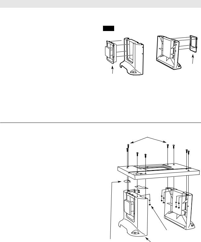
TABLE LEG INSERTS (FIG. 1)
The router table includes two table leg inserts:
•Storage panel for convenient storage of accessories
•Cord Wrap Panel
The table leg inserts must be installed before attaching the table top.
1.Place the table leg insert into the opening in the table leg so that it is positioned at the very top of the opening.
2.Press the insert in so that it is completely flush with the leg.
3.Push the insert down as far as it will go to lock it in place.
NOTE: The cord wrap panel has two tabs at the top of the panel that lock under the table top. These tabs help prevent the panel from coming unhooked when wrapping or unwrapping the cord.
FIG. 1
CORD WRAP
PANEL
STORAGE
PANEL
TOOLS REQUIRED (not included) |
|
|
|
FIG. 2 |
1/4-20x1-1/2″ CARRIAGE |
||
• |
Phillips screwdriver |
|
BOLTS |
• Small sized adjustable wrench |
|
|
|
• |
Tape with adhesive backing (optional) |
|
|
ROUTER TABLE LEGS (FIG. 2A)
1. Insert eight 1/4-20x1-1/2″ long carriage bolts (39) through the router table top as shown in Fig. 2.
2.Place a leg reinforcement over each set of
carriage bolts.
3. Assemble the legs to the router table as shown in the figure.
4. Assemble a 9/32″ ID x 5/8 OD″ x 1/16″ thick washer (36) and a 1/4-20 “KEPS” nut (32) onto each of the bolts.
5. Securely tighten the fasteners.
NOTE: It may be easier to assemble the legs by laying the router table on its front or back, or by using adhesive tape over the carriage bolt heads to hold
them in place and turning the router table upside down.
LEG |
LEG |
REINFORCEMENTS |
9/32 x 5/8 x 1/16″
WASHER
1/4-20 KEPS NUT
10
 Loading...