


Rexroth GTE
Table of contents
 Loading...
Bosch Rexroth GTE, Rexroth GTE040, Rexroth GTE060, Rexroth GTE160, Rexroth GTE080 Project Planning Manual
...
Electric Drives
and Controls Pneumatics
Service
Linear Motion and
Assembly Technologies
Hydraulics
LSA Control S.L. www.lsa-control.com comercial@lsa-control.com (+34) 960 62 43 01
Bosch Rexroth AG DOK-GEAR**-GTE********-PR06-EN-P
LSA Control S.L. www.lsa-control.com comercial@lsa-control.com (+34) 960 62 43 01
Rexroth GTE Planetary Gearboxes
Title
Type of Documentation
Document Typecode
Internal File Reference
Record of Revision
Copyright
Validity
Published by
Note
Rexroth GTE
Planetary Gearboxes
Project Planning Manual
DOK-GEAR**-GTE********-PR06-EN-P
RS-20ad79a1d989be610a6846a0004ed7c2-3-en-US-13
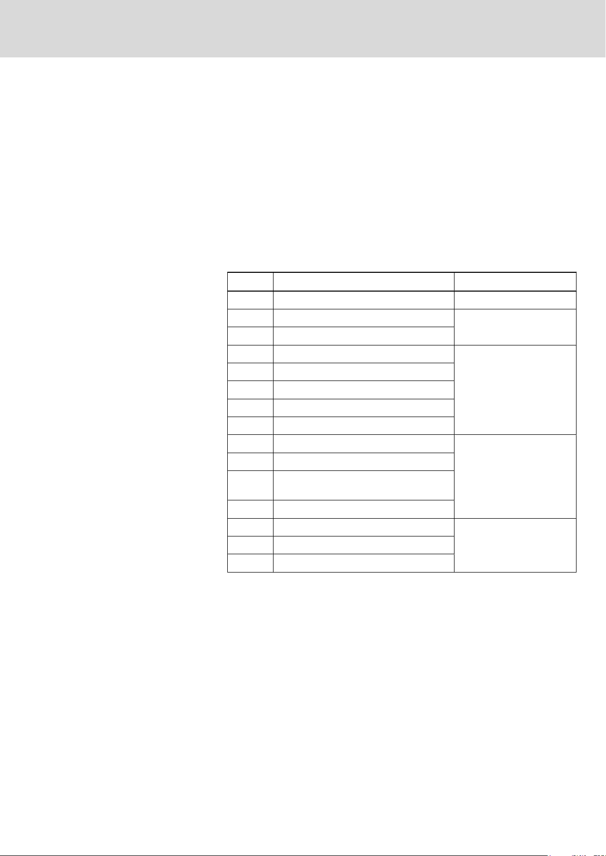
Edition Release Date Notes
DOK-GEAR**-GTE********-PR01-EN-P 12/2004 First edition
DOK-GEAR**-GTE********-PR02-EN-P 04/2005 Revision
DOK-GEAR**-GTE********-PR03-EN-P 01/2006 Revision
DOK-GEAR**-GTE********-PR04-EN-P 07/2009 Revision
DOK-GEAR**-GTE********-PR05-EN-P 11/2009 Revision
DOK-GEAR**-GTE********-PR06-EN-P 05/2010
(02/2011)
Revision type code (Fig.
7.1, Fig. 7.3)
© Bosch Rexroth AG, 2009
Copying
this document, giving it to others and the use or communication of the
contents thereof without express authority, are forbidden. Offenders are liable
for the payment of damages. All rights are reserved in the event of the grant of
a patent or the registration of a utility model or design (DIN 34-1).
The specified data is for product description purposes only and may not be
deemed to be guaranteed unless expressly confirmed in the contract. All rights
are reserved with respect to the content of this documentation and the availa‐
bility of the product.
Bosch Rexroth AG
Bgm.-Dr.-Nebel-Str. 2 ■ 97816 Lohr a. Main, Germany
Phone +49 (0)93 52 / 40-0 ■ Fax +49 (0)93 52 / 40-48 85
http://www.boschrexroth.com/
Dept.DCC/EDM (MB)
This document has been printed on chlorine-free bleached paper.

DOK-GEAR**-GTE********-PR06-EN-P
LSA Control S.L. www.lsa-control.com comercial@lsa-control.com (+34) 960 62 43 01
Rexroth GTE Planetary Gearboxes
Bosch Rexroth AG I/85
Table of Contents
Table of Contents
Page
1 Introduction to the Product............................................................................................. 5
1.1
1.2 About this Documentation....................................................................................................................... 7
1.2.1 General Information............................................................................................................................. 7
1.2.2 Standards............................................................................................................................................ 7
2 Important Instructions on Use........................................................................................ 9
2.1 Intended Use.......................................................................................................................................... 9
2.1.1 General Information............................................................................................................................. 9
2.1.2 Areas of Use and Application.............................................................................................................. 9
2.2 Non-Intended Use................................................................................................................................. 10
GTE Planetary Gearboxes...................................................................................................................... 5
3 Safety Instructions for Electric Drives and Controls .................................................... 11
3.1 Definitions of Terms.............................................................................................................................. 11
3.2 General Information.............................................................................................................................. 12
3.2.1 Using the Safety Instructions and Passing Them on to Others......................................................... 12
3.2.2 Requirements for Safe Use............................................................................................................... 12
3.2.3 Hazards by Improper Use.................................................................................................................. 13
3.3 Instructions with Regard to Specific Dangers....................................................................................... 14
3.3.1 Protection Against Contact with Electrical Parts and Housings......................................................... 14
3.3.2 Protective Extra-Low Voltage as Protection Against Electric Shock ................................................ 15
3.3.3 Protection Against Dangerous Movements....................................................................................... 15
3.3.4 Protection Against Magnetic and Electromagnetic Fields During Operation and Mounting.............. 17
3.3.5 Protection Against Contact With Hot Parts........................................................................................ 17
3.3.6 Protection During Handling and Mounting......................................................................................... 17
3.3.7 Battery Safety.................................................................................................................................... 18
3.3.8 Protection Against Pressurized Systems........................................................................................... 18
3.4 Explanation of Signal Words and the Safety Alert Symbol................................................................... 19
4 Dimensioning and Selection........................................................................................ 21
4.1 Dimensioning........................................................................................................................................ 21
4.2 Selection............................................................................................................................................... 22
5 Application Notes ........................................................................................................ 25
5.1 Operating Conditions............................................................................................................................ 25
5.1.1 General Information........................................................................................................................... 25
5.1.2 Operating Mode S5 (Intermitted Operation)...................................................................................... 26
5.1.3 Operating Mode S1 (Continuous Operation ) ................................................................................... 26
5.2 Operating Gearboxes or Motor-Gearbox Combinations in Hazardous Areas (ATEX).......................... 26
5.3 Mechanical Features............................................................................................................................ 27
5.4 Combination Possibilities of GTE Planetary Gearboxes with Motors................................................... 29

II/85
LSA Control S.L. www.lsa-control.com comercial@lsa-control.com (+34) 960 62 43 01
Table of Contents
Bosch Rexroth AG DOK-GEAR**-GTE********-PR06-EN-P
Rexroth GTE Planetary Gearboxes
Page
6 Technical Data............................................................................................................. 31
6.1 Technical Data for Intermittent and Continuous Operation................................................................... 31
6.2 Maximum Transferable Output Torque................................................................................................. 35
6.3 Thermal Specifications for S1 Operation.............................................................................................. 36
6.4 Technical Data at Increased Lifetime................................................................................................... 37
6.5 Limiting Temperature Curves to Determine Higher S1-Speed............................................................. 37
6.6 Permitted Shaft Load............................................................................................................................ 43
6.7 GTE040................................................................................................................................................ 44
6.8 GTE060................................................................................................................................................ 45
6.9 GTE080................................................................................................................................................ 46
6.10 GTE120................................................................................................................................................ 47
6.11 GTE160................................................................................................................................................ 48
7 Specifications............................................................................................................... 49
7.1 GTE040................................................................................................................................................ 49
7.2 GTE060................................................................................................................................................ 50
7.3 GTE080................................................................................................................................................ 51
7.4 GTE120................................................................................................................................................ 52
7.5 GTE160................................................................................................................................................ 53
8 Type Codes.................................................................................................................. 55
8.1 Notes on Connecting a Motor acc. to ATEX Standard......................................................................... 55
8.2 Type Code GTE040.............................................................................................................................. 55
8.3 Type Code GTE060.............................................................................................................................. 56
8.4 Type Code GTE080.............................................................................................................................. 57
8.5 Type Code GTE120.............................................................................................................................. 58
8.6 Type Code GTE160.............................................................................................................................. 59
9 Handling, Transport and Storage................................................................................. 61
9.1 Handling................................................................................................................................................ 61
9.1.1 Identifying the Goods......................................................................................................................... 61
9.1.2 Name Plates...................................................................................................................................... 61
9.2 Transport and Storage.......................................................................................................................... 62
10 Mounting...................................................................................................................... 65
10.1 Skilled Personnel.................................................................................................................................. 65
10.2 Motor Mounting..................................................................................................................................... 65
10.2.1 General Information........................................................................................................................... 65
10.2.2 Mounting Procedure.......................................................................................................................... 65
10.3 Gearbox Mounting................................................................................................................................ 68
11 Commissioning, Operation and Maintenance.............................................................. 69
11.1 Start-Up................................................................................................................................................ 69
11.1.1 General Information........................................................................................................................... 69

DOK-GEAR**-GTE********-PR06-EN-P
LSA Control S.L. www.lsa-control.com comercial@lsa-control.com (+34) 960 62 43 01
Rexroth GTE Planetary Gearboxes
11.1.2 Preparation........................................................................................................................................ 69
11.1.3
11.2 Deactivation.......................................................................................................................................... 70
11.3 Disassembly......................................................................................................................................... 70
11.4 Maintenance......................................................................................................................................... 70
11.4.1 General Information........................................................................................................................... 70
11.4.2 Measures........................................................................................................................................... 71
11.5 Troubleshooting ................................................................................................................................... 71
11.5.1 General Information........................................................................................................................... 71
11.5.2 Excess Temperature of Gearbox Housing........................................................................................ 71
11.5.3 Gearbox-Motor Unit Generates Vibrations........................................................................................ 72
11.5.4 Specified Position is not Attained...................................................................................................... 72
Bulk Head Connector........................................................................................................................ 69
Bosch Rexroth AG III/85
Table of Contents
Page
12 Ordering Designations................................................................................................. 73
12.1 General Information.............................................................................................................................. 73
12.2 Notes on Connecting a Motor acc. to ATEX Standard......................................................................... 73
13 "Old" Technical Data.................................................................................................... 75
13.1 "Old" Technical Data for Intermittent and Continuous Operation......................................................... 75
14 Environmental Protection and Disposal ...................................................................... 79
14.1 Environmental Protection...................................................................................................................... 79
14.2 Disposal................................................................................................................................................ 79
15 Service and Support.................................................................................................... 81
Index............................................................................................................................ 83

IV/85
LSA Control S.L. www.lsa-control.com comercial@lsa-control.com (+34) 960 62 43 01
Bosch Rexroth AG DOK-GEAR**-GTE********-PR06-EN-P
Rexroth GTE Planetary Gearboxes
DOK-GEAR**-GTE********-PR06-EN-P
LSA Control S.L. www.lsa-control.com comercial@lsa-control.com (+34) 960 62 43 01
Rexroth GTE Planetary Gearboxes
1 Introduction to the Product
Bosch Rexroth AG 5/85
Introduction to the Product
1.1
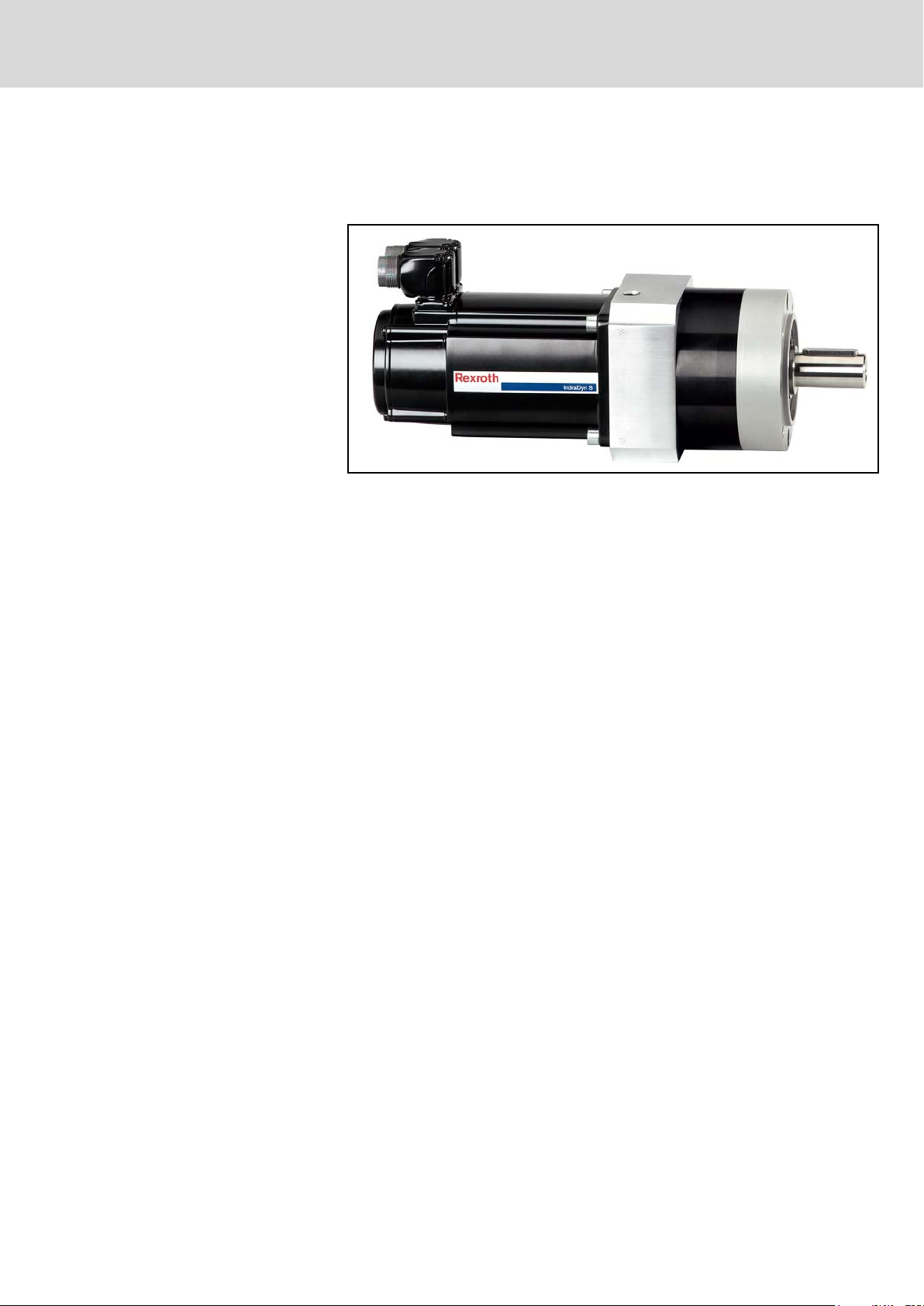
GTE Planetary Gearboxes
Application
Fig.1-1: Mounting example: GTE planetary gearboxes mounted on IndraDyn S
In combination with the drive and control system of Rexroth, GTE planetary
gearboxes provide a low-cost automation system for various sectors of industry.
They are well-suited for use with gear racks or toothed belts in handling systems
with high speed and accelerations (e.g.: loader and robots).
The low-backlash with shave-grinded (honed) planet wheels permits the exe‐
cution of exact positioning tasks. Furthermore, the gearboxes are suited for S1operation-required for application in e.g. the printing sector.
motors
6/85
LSA Control S.L. www.lsa-control.com comercial@lsa-control.com (+34) 960 62 43 01
Bosch Rexroth AG DOK-GEAR**-GTE********-PR06-EN-P
Introduction to the Product
Gradations
Rexroth GTE Planetary Gearboxes
Mode of Functioning
High Operational Reliability
High Performance Data
Easy to Mount to Machine
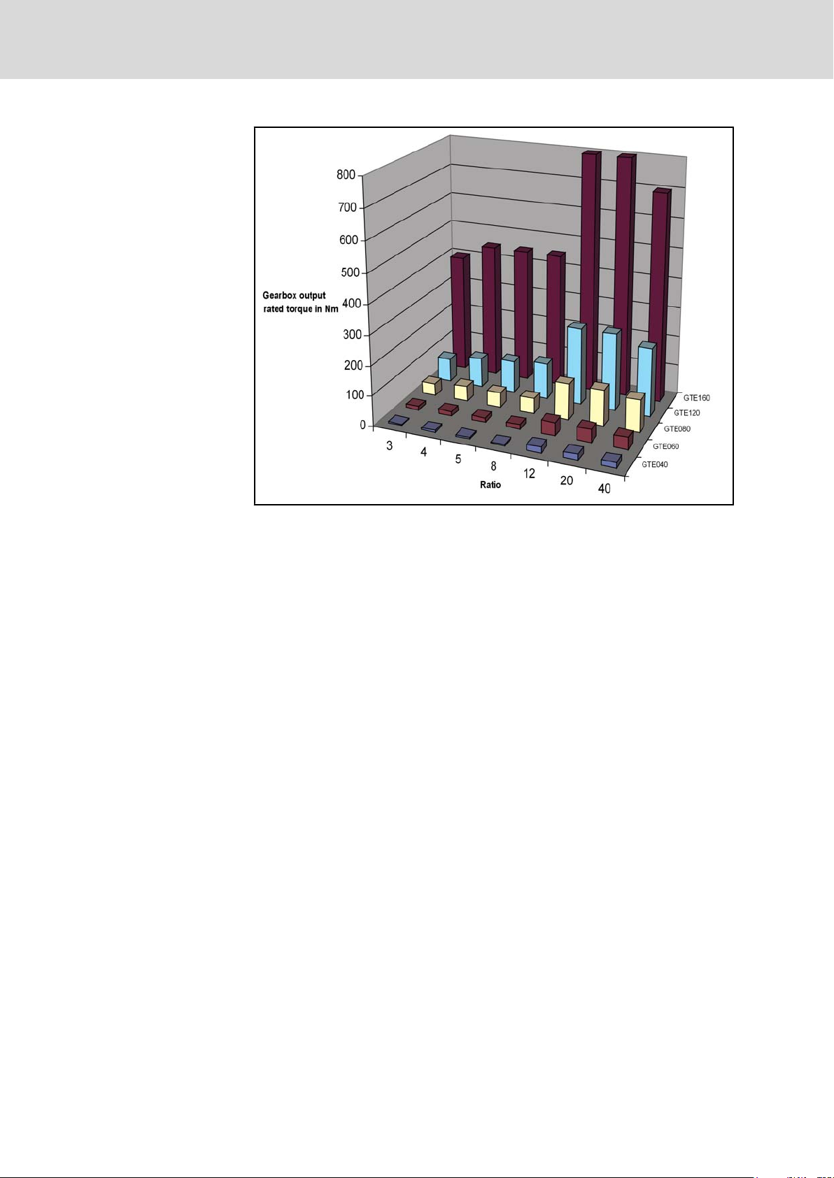
Fig.1-2: Nominal torque gradation of GTE planetary gearboxes
The GTE series of planetary gearboxes offers a coaxial input and output. The
output shaft of the motor is connected to the sun gear with a non-positive com‐
pression clamp coupling. This sun gear drives three planetary wheels, which
roll off on an internal gear with internal gear teeth, as a single-stage gearbox
and four planetary wheels as a two-stage gearbox. The planetary gears are
fixed in the planet carrier, which acts as the output. By dividing the load among
the planetary gear on three or four planetary wheels, a balanced force splitting
occurs. This allows for a very compact gearbox with a high power density.
● Maintenance-free operation through lifetime lubrication
● Use under adverse environmental conditions is possible due to the com‐
pletely enclosed IP54 design.
● Safe and lasting sealing by abradant bearing sealants.
● Hermetically sealed housing
● Non-positive from backlash-free torque transmission via the compression
coupling
● High accuracy via shave grinded (honed) planetary wheels, low backlash
gearing with low torque play.
● High efficiency, low temperature and minimum power loss made possible
by using the smallest possible seal diameters.
● Low running noise by optimized gear profiles.
● High emergency stop torque made possible by internal transferred power.
● Highly dynamic because of inertia
● Low weight through compact design
● The high radial-load capability and tilt resistance makes it possible to di‐
rectly mount a pinion or pulley.
● The design of the output shaft with a solid shaft shoulder makes axial
tightening of output elements simple.
DOK-GEAR**-GTE********-PR06-EN-P
LSA Control S.L. www.lsa-control.com comercial@lsa-control.com (+34) 960 62 43 01
Rexroth GTE Planetary Gearboxes
Bosch Rexroth AG 7/85
Introduction to the Product
● The
gearbox can be mounted in any position. Due to the defined bearing
position and pump current a sufficient lubricant supply is always ensured.
● The output elements can be mounted in two different ways:
– non-positive shaft-hub connection by means of a plain output hollow
shaft, or
– connection by means of an output shaft with keyway
1.2 About this Documentation
1.2.1 General Information
This document contains safety regulations, technical data, and operating in‐
structions for gearboxes. The individual chapters can be subdivided into the
following focal points:
Chapter
1 Introduction to the Product General Information
2 Important Instructions on Use
3 Notes Regarding Safety
4 Dimensioning and Selection
5 Application Notes
6 technical data
7 Specifications
Title Contents
Safety
Product description
ners and designers)
(for plan‐
1.2.2 Standards
8 Type Codes
9 Handling, Transport and Storage
10 Assembly
11 Commissioning, Operation and Mainte‐
nance
12 Ordering Data
13 Appendix
15 Index
Fig.1-3: Document structure
Practise(for
maintenance personnel)
General Information14 Service & Support
operating and
This documentation refers to German, European and international technical
standards. Documents and sheets on standards underlie the protection by
copyright and may not be passed on to third parties by REXROTH INDRAMAT.
If need be, please contact the authorized sales outlets or, in Germany, directly:
BEUTH Verlag GmbH
Burggrafenstrasse 6

8/85
LSA Control S.L. www.lsa-control.com comercial@lsa-control.com (+34) 960 62 43 01
Bosch Rexroth AG DOK-GEAR**-GTE********-PR06-EN-P
Introduction to the Product
Rexroth GTE Planetary Gearboxes
10787 Berlin, Germany
Phone 49 (0) 30 – 26 01-22 60, Fax +49 (0) 30 – 26 01-12 60
Internet: http://www.din.be/beuth
Email: postmaster@beuth.de
Your Feedback
Your
experiences are an essential part of the process of improving both the
product and the documentation.
Please do not hesitate to inform us of any error you detect in this documentation
or of any modifications you might desire. We would appreciate your feedback.
Please send your remarks to:
Bosch Rexroth AG
Dept. DCC/EDM1
Buergermeister-Dr.-Nebel-Strasse 2
97816 Lohr am Main, Germany
Fax +49 (0) 93 52 / 40 43 80
DOK-GEAR**-GTE********-PR06-EN-P
LSA Control S.L. www.lsa-control.com comercial@lsa-control.com (+34) 960 62 43 01
Rexroth GTE Planetary Gearboxes
2 Important Instructions on Use
Bosch Rexroth AG 9/85
Important Instructions on Use
2.1
Intended Use
2.1.1 General Information
Introduction
Rexroth products are developed and manufactured according to the state of
the art. Before they are delivered, they are inspected to ensure that they operate
safely.
The products must only be used as intended. If they are inappropriate used,
situations may arise resulting in injuries to property and persons.
Before using the Bosch Rexroth products, the following condition precedent
must be fulfilled so as to ensure that they are used as intended:
● Everyone
read and understand the corresponding notes regarding safety and re‐
garding the intended use.
● If the products are hardware, they must be kept in their original state, i.e.
no constructional modifications must be made. Software products must
not be decompiled; their source codes must not be modified.
● Damaged or improperly working products must not be installed or put into
operation.
● It must be ensured that the products are installed according to the regu‐
lations specified in the documentation.
Rexroth, as the manufacturer, does not provide any warranty, as‐
sume
any liability, or pay any damages for damage caused by
products not being used as intended. Any risks resulting from the
products not being used as intended are the sole responsibility of
the user.
who in any way whatsoever handles one of our products must
2.1.2 Areas of Use and Application
Typical application ranges of the GTE planetary gearboxes are:
● Handling and Mounting systems,
● Packaging and Food-processing machines,
● Printing and Paper-processing machines and
Controlling and monitoring of the motor/-gearbox combination may require con‐
nection of additional sensors and actuators.
The gearboxes may only be used with the accessories specified in
the
documentation. Components that are not explicitly mentioned
must neither be attached nor connected. The same is true for cables
and lines.
The operation must only be carried out in the explicitly mentioned
configurations
software and firmware specified in the corresponding functional de‐
scription.
Any drive controller must be programmed before startup, in order to ensure that
the motor executes the functions specific to the particular application.
and combinations of the component and with the

10/85
LSA Control S.L. www.lsa-control.com comercial@lsa-control.com (+34) 960 62 43 01
Important Instructions on Use
Bosch Rexroth AG DOK-GEAR**-GTE********-PR06-EN-P
The gearboxes may only be operated under the assembly, mounting and in‐
stallation
conditions (temperature, degree of protection, humidity, EMC, and the like)
specified in this documentation.
2.2 Non-Intended Use
Any use of gearboxes outside of the fields of application mentioned above or
under operating conditions and technical data other than those specified in this
documentation is considered as "non-intended use".
Planetary gearboxes may not be used if . . .
● They are subject to operating conditions which do not comply with the
ambient conditions described above. E.g. operation under water, under
extreme variations in temperature or extreme maximum temperatures is
not permitted.
● the intended application is not explicitly released by Bosch Rexroth.
Please make absolutely sure that the instructions given in the general
safety notes are also complied with!
Rexroth GTE Planetary Gearboxes
conditions, in the normal position, and under the environmental

DOK-GEAR**-GTE********-PR06-EN-P
LSA Control S.L. www.lsa-control.com comercial@lsa-control.com (+34) 960 62 43 01
Rexroth GTE Planetary Gearboxes
Safety Instructions for Electric Drives and Controls
Bosch Rexroth AG 11/85
3 Safety Instructions for Electric Drives and Controls
3.1
Definitions of Terms
Application Documentation
Component
Control System
Device
Electrical Equipment
Electric Drive System
Installation
Machine
Manufacturer
Product
Project Planning Manual
Qualified Persons
Application documentation comprises the entire documentation used to inform
the user of the product about the use and safety-relevant features for config‐
uring, integrating, installing, mounting, commissioning, operating, maintaining,
repairing and decommissioning the product. The following terms are also used
for this kind of documentation: User Guide, Operation Manual, Commissioning
Manual, Instruction Manual, Project Planning Manual, Application Manual, etc.
A component is a combination of elements with a specified function, which are
part of a piece of equipment, device or system. Components of the electric drive
and control system are, for example, supply units, drive controllers, mains
choke, mains filter, motors, cables, etc.
A control system comprises several interconnected control components placed
on the market as a single functional unit.
A device is a finished product with a defined function, intended for users and
placed on the market as an individual piece of merchandise.
Electrical equipment encompasses all devices used to generate, convert, trans‐
mit, distribute or apply electrical energy, such as electric motors, transformers,
switching devices, cables, lines, power-consuming devices, circuit board as‐
semblies, plug-in units, control cabinets, etc.
An electric drive system comprises all components from mains supply to motor
shaft; this includes, for example, electric motor(s), motor encoder(s), supply
units and drive controllers, as well as auxiliary and additional components, such
as mains filter, mains choke and the corresponding lines and cables.
An installation consists of several devices or systems interconnected for a de‐
fined purpose and on a defined site which, however, are not intended to be
placed on the market as a single functional unit.
A machine is the entirety of interconnected parts or units at least one of which
is movable. Thus, a machine consists of the appropriate machine drive ele‐
ments, as well as control and power circuits, which have been assembled for
a specific application. A machine is, for example, intended for processing,
treatment, movement or packaging of a material. The term "machine" also cov‐
ers a combination of machines which are arranged and controlled in such a way
that they function as a unified whole.
The manufacturer is an individual or legal entity bearing responsibility for the
design and manufacture of a product which is placed on the market in the in‐
dividual's or legal entity's name. The manufacturer can use finished products,
finished parts or finished elements, or contract out work to subcontractors.
However, the manufacturer must always have overall control and possess the
required authority to take responsibility for the product.
Examples of a product: Device, component, part, system, software, firmware,
among other things.
A project planning manual is part of the application documentation used to
support the sizing and planning of systems, machines or installations.
In terms of this application documentation, qualified persons are those persons
who are familiar with the installation, mounting, commissioning and operation
of the components of the electric drive and control system, as well as with the
hazards this implies, and who possess the qualifications their work requires. To
comply with these qualifications, it is necessary, among other things,

12/85
LSA Control S.L. www.lsa-control.com comercial@lsa-control.com (+34) 960 62 43 01
Safety Instructions for Electric Drives and Controls
Bosch Rexroth AG DOK-GEAR**-GTE********-PR06-EN-P
Rexroth GTE Planetary Gearboxes
1) to be trained, instructed or authorized to switch electric circuits and devices
safely on and off, to ground them and to mark them
2) to be trained or instructed to maintain and use adequate safety equipment
3) to attend a course of instruction in first aid
User
A
user is a person installing, commissioning or using a product which has been
placed on the market.
3.2 General Information
3.2.1 Using the Safety Instructions and Passing Them on to Others
Do not attempt to install and operate the components of the electric drive and
control system without first reading all documentation provided with the product.
Read and understand these safety instructions and all user documentation prior
to working with these components. If you do not have the user documentation
for the components, contact your responsible Rexroth sales partner. Ask for
these documents to be sent immediately to the person or persons responsible
for the safe operation of the components.
If the component is resold, rented and/or passed on to others in any other form,
these safety instructions must be delivered with the component in the official
language of the user's country.
Improper use of these components, failure to follow the safety instructions in
this document or tampering with the product, including disabling of safety de‐
vices, could result in property damage, injury, electric shock or even death.
3.2.2 Requirements for Safe Use
Read the following instructions before initial commissioning of the components
of the electric drive and control system in order to eliminate the risk of injury
and/or property damage. You must follow these safety instructions.
● Rexroth is not liable for damages resulting from failure to observe the
safety instructions.
● Read the operating, maintenance and safety instructions in your language
before commissioning. If you find that you cannot completely understand
the application documentation in the available language, please ask your
supplier to clarify.
● Proper and correct transport, storage, mounting and installation, as well
as care in operation and maintenance, are prerequisites for optimal and
safe operation of the component.
● Only qualified persons may work with components of the electric drive and
control system or within its proximity.
● Only use accessories and spare parts approved by Rexroth.
● Follow the safety regulations and requirements of the country in which the
components of the electric drive and control system are operated.
● Only use the components of the electric drive and control system in the
manner that is defined as appropriate. See chapter "Appropriate Use".
● The ambient and operating conditions given in the available application
documentation must be observed.
● Applications for functional safety are only allowed if clearly and explicitly
specified in the application documentation "Integrated Safety Technolo‐
gy". If this is not the case, they are excluded. Functional safety is a safety

DOK-GEAR**-GTE********-PR06-EN-P
LSA Control S.L. www.lsa-control.com comercial@lsa-control.com (+34) 960 62 43 01
Rexroth GTE Planetary Gearboxes
Bosch Rexroth AG 13/85
Safety Instructions for Electric Drives and Controls
concept in which measures of risk reduction for personal safety depend
on electrical, electronic or programmable control systems.
● The
● Commissioning of the delivered components is only allowed once it is sure
● Operation is only allowed if the national EMC regulations for the applica‐
● The instructions for installation in accordance with EMC requirements can
● The technical data, connection and installation conditions of the compo‐
information given in the application documentation with regard to the
use of the delivered components contains only examples of applications
and suggestions.
The machine and installation manufacturers must
– make sure that the delivered components are suited for their individ‐
ual application and check the information given in this application
documentation with regard to the use of the components,
– make sure that their individual application complies with the appli‐
cable safety regulations and standards and carry out the required
measures, modifications and complements.
that the machine or installation in which the components are installed
complies with the national regulations, safety specifications and standards
of the application.
tion are met.
be found in the section on EMC in the respective application documenta‐
tion.
The machine or installation manufacturer is responsible for compliance
with the limit values as prescribed in the national regulations.
nents are specified in the respective application documentations and must
be followed at all times.
National regulations which the user must take into account
● European countries: In accordance with European EN standards
● United States of America (USA):
– National Electrical Code (NEC)
– National Electrical Manufacturers Association (NEMA), as well as
local engineering regulations
– Regulations of the National Fire Protection Association (NFPA)
● Canada: Canadian Standards Association (CSA)
● Other countries:
– International Organization for Standardization (ISO)
– International Electrotechnical Commission (IEC)
3.2.3 Hazards by Improper Use
● High electrical voltage and high working current! Danger to life or serious
injury by electric shock!
● High electrical voltage by incorrect connection! Danger to life or injury by
electric shock!
● Dangerous movements! Danger to life, serious injury or property damage
by unintended motor movements!
● Health hazard for persons with heart pacemakers, metal implants and
hearing aids in proximity to electric drive systems!
● Risk of burns by hot housing surfaces!

14/85
LSA Control S.L. www.lsa-control.com comercial@lsa-control.com (+34) 960 62 43 01
Safety Instructions for Electric Drives and Controls
Bosch Rexroth AG DOK-GEAR**-GTE********-PR06-EN-P
Rexroth GTE Planetary Gearboxes
● Risk
● Risk of injury by improper handling of batteries!
● Risk of injury by improper handling of pressurized lines!
of injury by improper handling! Injury by crushing, shearing, cutting,
hitting!
3.3 Instructions with Regard to Specific Dangers
3.3.1 Protection Against Contact with Electrical Parts and Housings
This section concerns components of the electric drive and control
system with voltages of more than 50 volts.
Contact with parts conducting voltages above 50 volts can cause personal
danger
and control system, it is unavoidable that some parts of these components
conduct dangerous voltage.
High electrical voltage! Danger to life, risk of injury by electric shock or serious
injury!
● Only qualified persons are allowed to operate, maintain and/or repair the
● Follow the general installation and safety regulations when working on
● Before switching on, the equipment grounding conductor must have been
● Even for brief measurements or tests, operation is only allowed if the
● Before accessing electrical parts with voltage potentials higher than 50 V,
● With electric components, observe the following aspects:
● Install the covers and guards provided for this purpose before switching
● Never touch electrical connection points of the components while power
● Do not remove or plug in connectors when the component has been pow‐
● Under specific conditions, electric drive systems can be operated at mains
● Secure built-in devices from penetrating foreign objects and water, as well
and electric shock. When operating components of the electric drive
components of the electric drive and control system.
power installations.
permanently connected to all electric components in accordance with the
connection diagram.
equipment grounding conductor has been permanently connected to the
points of the components provided for this purpose.
you must disconnect electric components from the mains or from the pow‐
er supply unit. Secure the electric component from reconnection.
Always wait 30 minutes after switching off power to allow live capacitors
to discharge before accessing an electric component. Measure the elec‐
trical voltage of live parts before beginning to work to make sure that the
equipment is safe to touch.
on.
is turned on.
ered.
protected by residual-current-operated circuit-breakers sensitive to uni‐
versal current (RCDs/RCMs).
as from direct contact, by providing an external housing, for example a
control cabinet.

DOK-GEAR**-GTE********-PR06-EN-P
LSA Control S.L. www.lsa-control.com comercial@lsa-control.com (+34) 960 62 43 01
Rexroth GTE Planetary Gearboxes
Safety Instructions for Electric Drives and Controls
High housing voltage and high leakage current! Danger to life, risk of injury by
electric shock!
● Before
components of the electric drive and control system to the equipment
grounding conductor at the grounding points.
● Connect the equipment grounding conductor of the components of the
electric drive and control system permanently to the main power supply at
all times. The leakage current is greater than 3.5 mA.
● Establish an equipment grounding connection with a copper wire of a
cross section of at least 10 mm2 (8 AWG) or additionally run a second
equipment grounding conductor of the same cross section as the original
equipment grounding conductor.
switching on and before commissioning, ground or connect the
Bosch Rexroth AG 15/85
3.3.2 Protective Extra-Low Voltage as Protection Against Electric Shock
Protective extra-low voltage is used to allow connecting devices with basic in‐
sulation to extra-low voltage circuits.
On components of an electric drive and control system provided by Rexroth, all
connections and terminals with voltages between 5 and 50 volts are PELV
("Protective Extra-Low Voltage") systems. It is allowed to connect devices
equipped with basic insulation (such as programming devices, PCs, notebooks,
display units) to these connections.
Danger to life, risk of injury by electric shock! High electrical voltage by incorrect
connection!
If extra-low voltage circuits of devices containing voltages and circuits of more
than 50 volts (e.g., the mains connection) are connected to Rexroth products,
the connected extra-low voltage circuits must comply with the requirements for
PELV ("Protective Extra-Low Voltage").
3.3.3 Protection Against Dangerous Movements
Dangerous movements can be caused by faulty control of connected motors.
Some common examples are:
● Improper or wrong wiring or cable connection
● Operator errors
● Wrong input of parameters before commissioning
● Malfunction of sensors and encoders
● Defective components
● Software or firmware errors
These errors can occur immediately after equipment is switched on or even
after an unspecified time of trouble-free operation.
The monitoring functions in the components of the electric drive and control
system will normally be sufficient to avoid malfunction in the connected drives.
Regarding personal safety, especially the danger of injury and/or property dam‐
age, this alone cannot be relied upon to ensure complete safety. Until the
integrated monitoring functions become effective, it must be assumed in any
case that faulty drive movements will occur. The extent of faulty drive move‐
ments depends upon the type of control and the state of operation.

16/85
LSA Control S.L. www.lsa-control.com comercial@lsa-control.com (+34) 960 62 43 01
Bosch Rexroth AG DOK-GEAR**-GTE********-PR06-EN-P
Safety Instructions for Electric Drives and Controls
Dangerous movements! Danger to life, risk of injury, serious injury or property
damage!
A risk
assessment must be prepared for the installation or machine, with its
specific conditions, in which the components of the electric drive and control
system are installed.
As a result of the risk assessment, the user must provide for monitoring func‐
tions and higher-level measures on the installation side for personal safety. The
safety regulations applicable to the installation or machine must be taken into
consideration. Unintended machine movements or other malfunctions are pos‐
sible if safety devices are disabled, bypassed or not activated.
To avoid accidents, injury and/or property damage:
● Keep free and clear of the machine’s range of motion and moving machine
parts. Prevent personnel from accidentally entering the machine’s range
of motion by using, for example:
– Safety fences
– Safety guards
– Protective coverings
– Light barriers
● Make sure the safety fences and protective coverings are strong enough
to resist maximum possible kinetic energy.
● Mount emergency stopping switches in the immediate reach of the oper‐
ator. Before commissioning, verify that the emergency stopping equip‐
ment works. Do not operate the machine if the emergency stopping switch
is not working.
● Prevent unintended start-up. Isolate the drive power connection by means
of OFF switches/OFF buttons or use a safe starting lockout.
● Make sure that the drives are brought to safe standstill before accessing
or entering the danger zone.
● Additionally secure vertical axes against falling or dropping after switching
off the motor power by, for example,
– mechanically securing the vertical axes,
– adding an external braking/arrester/clamping mechanism or
– ensuring sufficient counterbalancing of the vertical axes.
● The standard equipment motor holding brake or an external holding brake
controlled by the drive controller is not sufficient to guarantee personal
safety!
● Disconnect electrical power to the components of the electric drive and
control system using the master switch and secure them from reconnec‐
tion ("lock out") for:
– Maintenance and repair work
– Cleaning of equipment
– Long periods of discontinued equipment use
● Prevent the operation of high-frequency, remote control and radio equip‐
ment near components of the electric drive and control system and their
supply leads. If the use of these devices cannot be avoided, check the
machine or installation, at initial commissioning of the electric drive and
control system, for possible malfunctions when operating such high-fre‐
quency, remote control and radio equipment in its possible positions of
normal use. It might possibly be necessary to perform a special electro‐
magnetic compatibility (EMC) test.
Rexroth GTE Planetary Gearboxes

DOK-GEAR**-GTE********-PR06-EN-P
LSA Control S.L. www.lsa-control.com comercial@lsa-control.com (+34) 960 62 43 01
Rexroth GTE Planetary Gearboxes
Bosch Rexroth AG 17/85
Safety Instructions for Electric Drives and Controls
3.3.4
Protection Against Magnetic and Electromagnetic Fields During Oper‐
ation and Mounting
Magnetic and electromagnetic fields generated by current-carrying conductors
or permanent magnets of electric motors represent a serious danger to persons
with heart pacemakers, metal implants and hearing aids.
Health hazard for persons with heart pacemakers, metal implants and hearing
aids in proximity to electric components!
● Persons with heart pacemakers and metal implants are not allowed to
enter the following areas:
– Areas in which components of the electric drive and control systems
are mounted, commissioned and operated.
– Areas in which parts of motors with permanent magnets are stored,
repaired or mounted.
● If it is necessary for somebody with a heart pacemaker to enter such an
area, a doctor must be consulted prior to doing so. The noise immunity of
implanted heart pacemakers differs so greatly that no general rules can
be given.
● Those with metal implants or metal pieces, as well as with hearing aids,
must consult a doctor before they enter the areas described above.
3.3.5 Protection Against Contact With Hot Parts
Hot surfaces of components of the electric drive and control system. Risk of
burns!
● Do not touch hot surfaces of, for example, braking resistors, heat sinks,
supply units and drive controllers, motors, windings and laminated cores!
● According to the operating conditions, temperatures of the surfaces can
be higher than 60 °C (140 °F) during or after operation.
● Before touching motors after having switched them off, let them cool down
for a sufficient period of time. Cooling down can require up to 140 mi‐
nutes! The time required for cooling down is approximately five times the
thermal time constant specified in the technical data.
● After switching chokes, supply units and drive controllers off, wait 15 mi‐
nutes to allow them to cool down before touching them.
● Wear safety gloves or do not work at hot surfaces.
● For certain applications, and in accordance with the respective safety reg‐
ulations, the manufacturer of the machine or installation must take meas‐
ures to avoid injuries caused by burns in the final application. These
measures can be, for example: Warnings at the machine or installation,
guards (shieldings or barriers) or safety instructions in the application
documentation.
3.3.6 Protection During Handling and Mounting
Risk of injury by improper handling! Injury by crushing, shearing, cutting, hitting!
● Observe the relevant statutory regulations of accident prevention.
● Use suitable equipment for mounting and transport.
● Avoid jamming and crushing by appropriate measures.

18/85
LSA Control S.L. www.lsa-control.com comercial@lsa-control.com (+34) 960 62 43 01
Safety Instructions for Electric Drives and Controls
Bosch Rexroth AG DOK-GEAR**-GTE********-PR06-EN-P
● Always use suitable tools. Use special tools if specified.
●
Use lifting equipment and tools in the correct manner.
● Use suitable protective equipment (hard hat, safety goggles, safety shoes,
safety gloves, for example).
● Do not stand under hanging loads.
● Immediately clean up any spilled liquids from the floor due to the risk of
slipping.
3.3.7 Battery Safety
Batteries consist of active chemicals in a solid housing. Therefore, improper
handling can cause injury or property damage.
Risk of injury by improper handling!
● Do not attempt to reactivate low batteries by heating or other methods (risk
of explosion and cauterization).
● Do not attempt to recharge the batteries as this may cause leakage or
explosion.
● Do not throw batteries into open flames.
● Do not dismantle batteries.
● When replacing the battery/batteries, do not damage the electrical parts
installed in the devices.
● Only use the battery types specified for the product.
Rexroth GTE Planetary Gearboxes
3.3.8
Environmental protection and disposal! The batteries contained in
the
product are considered dangerous goods during land, air, and
sea transport (risk of explosion) in the sense of the legal regulations.
Dispose of used batteries separately from other waste. Observe the
national regulations of your country.
Protection Against Pressurized Systems
According to the information given in the Project Planning Manuals, motors and
components cooled with liquids and compressed air can be partially supplied
with externally fed, pressurized media, such as compressed air, hydraulics oil,
cooling liquids and cooling lubricants. Improper handling of the connected sup‐
ply systems, supply lines or connections can cause injuries or property damage.
Risk of injury by improper handling of pressurized lines!
● Do not attempt to disconnect, open or cut pressurized lines (risk of explo‐
sion).
● Observe the respective manufacturer's operating instructions.
● Before dismounting lines, relieve pressure and empty medium.
● Use suitable protective equipment (safety goggles, safety shoes, safety
gloves, for example).
● Immediately clean up any spilled liquids from the floor due to the risk of
slipping.
DOK-GEAR**-GTE********-PR06-EN-P
LSA Control S.L. www.lsa-control.com comercial@lsa-control.com (+34) 960 62 43 01
Rexroth GTE Planetary Gearboxes
Bosch Rexroth AG 19/85
Safety Instructions for Electric Drives and Controls
Environmental protection and disposal! The agents (e.g., fluids)
used
to operate the product might not be environmentally friendly.
Dispose of agents harmful to the environment separately from other
waste. Observe the national regulations of your country.
3.4
Explanation of Signal Words and the Safety Alert Symbol
The Safety Instructions in the available application documentation contain spe‐
cific signal words (DANGER, WARNING, CAUTION or NOTICE) and, where
required, a safety alert symbol (in accordance with ANSI Z535.6-2006).
The signal word is meant to draw the reader's attention to the safety instruction
and identifies the hazard severity.
The safety alert symbol (a triangle with an exclamation point), which precedes
the signal words DANGER, WARNING and CAUTION, is used to alert the
reader to personal injury hazards.
DANGER
In case of non-compliance with this safety instruction, death or serious injury
will occur.
WARNING
In case of non-compliance with this safety instruction, death or serious injury
could occur.
CAUTION
In case of non-compliance with this safety instruction, minor or moderate injury
could occur.
NOTICE
In case of non-compliance with this safety instruction, property damage could
occur.

20/85
LSA Control S.L. www.lsa-control.com comercial@lsa-control.com (+34) 960 62 43 01
Bosch Rexroth AG DOK-GEAR**-GTE********-PR06-EN-P
Rexroth GTE Planetary Gearboxes
DOK-GEAR**-GTE********-PR06-EN-P
LSA Control S.L. www.lsa-control.com comercial@lsa-control.com (+34) 960 62 43 01
Rexroth GTE Planetary Gearboxes
4 Dimensioning and Selection
Bosch Rexroth AG 21/85
Dimensioning and Selection
4.1
Triangular operation with pause in‐
Dimensioning
terval
Applications for GTE planetary gearboxes are characterized by the following
speed-time-curves:
● Triangular speed curve with pause interval
● Operation with constant speed and pause interval
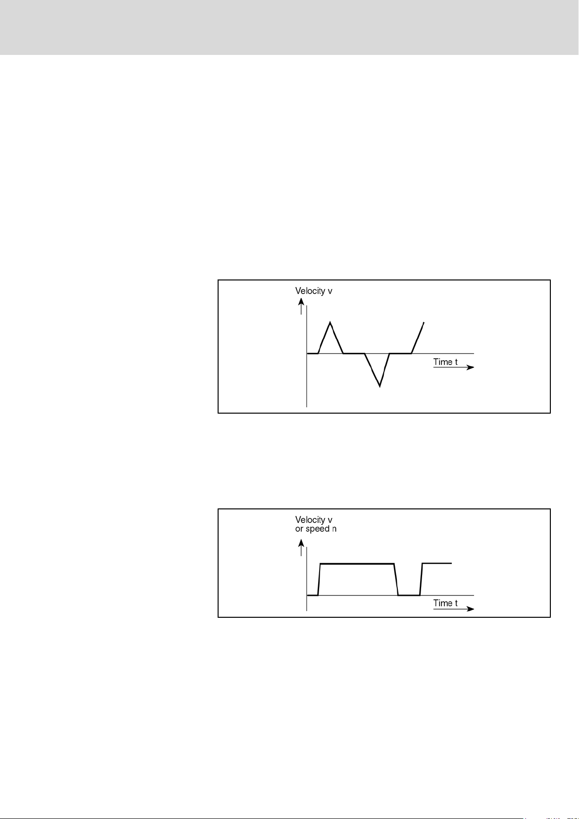
● Operation with trapezoidal speed curve and pause interval
● Continuous operation without pause interval (S1)
The speed-time curves define the dimension criteria.
This operating mode is characteristic for all highly-dynamic feeds. These are
often found in roll-feed mechanisms in the sheet-metal, paper, plastic and
packaging industries.
Continuous Operation with Pause
Interval
Triangular Operation with Pause In‐
terval
Fig.4-1: Speed-time curve for triangle operation
The dimensioning of this operation is mainly made according to the necessary
maximum torque M
n
.
average
and the average velocity V
max
resp. mean speed
average
This operation is characteristic for all highly-dynamic feeds. These are often
found in winding machines, drive rolls and in portioning devices in the sheetmetal, paper, plastic and packaging industry.
Fig.4-2: Speed-time diagram for operation with constant speed
The dimensioning of this operation is mainly made according to the necessary
maximum torque M
n
.
average
and the average velocity V
max
resp. mean speed
average
This mode of operation is characteristic for the most highly-dynamic feeds.
They can be found in loaders and handling systems in nearly all industry sec‐
tors.

22/85
LSA Control S.L. www.lsa-control.com comercial@lsa-control.com (+34) 960 62 43 01
Bosch Rexroth AG DOK-GEAR**-GTE********-PR06-EN-P
Dimensioning and Selection
Continuous operation without
pause interval (S1)
Rexroth GTE Planetary Gearboxes
Fig.4-3: Speed-time-graph for triangle operation
The dimensioning of this operation is mainly made according to the necessary
maximum torque M
n
.
average
and the average velocity V
max
resp. mean speed
average
This mode of operation is characteristic for drives in printing machines.
4.2 Selection
Drive-Determined Sizes
Dimensioning Criteria
Fig.4-4: Speed-time graph for constant speed
The dimensioning is made according to the necessary continuous torque M
dN
and the velocity v or the speed n.
The selection of the suitable motor/-gearbox combination, operating with a drive
control device, is to be taking in the following into consideration:
● Frictional torque
● Starting torque
● Processing torque
● Accelerating torque
● Effective speed
● Necessary speed
● ON time
The motor-gearbox combination must fulfill the following conditions:
● The necessary speed must be reached.
● The continuous torque rating of the motor-gearbox combination has to be
higher than the effective load torque.
● The intermittent torque has to be higher than the sum of the frictional,
starting and processing torque.
● The maximum torque has to be higher than the sum of frictional, weight
and processing torque.
● The required acceleration time has to be within the limit of the relevant
drive selection lists.

DOK-GEAR**-GTE********-PR06-EN-P
LSA Control S.L. www.lsa-control.com comercial@lsa-control.com (+34) 960 62 43 01
Rexroth GTE Planetary Gearboxes
Bosch Rexroth AG 23/85
Dimensioning and Selection
● The
thermal use-limit of the motor-gearbox combination must be adhered.
● The cycles of the operation modes S4 and S5 should not exceed 1,000
cycles per hour. If higher cycle rates are necessary, the GTM gearbox
must be derated accordingly (see Fig. 5-3).
It must be ensured that
● the
maximum motor torque is smaller than the maximum gear‐
box – input torque.
● the maximum motor speed is smaller than the maximum per‐
missible gearbox-input speed.

24/85
LSA Control S.L. www.lsa-control.com comercial@lsa-control.com (+34) 960 62 43 01
Bosch Rexroth AG DOK-GEAR**-GTE********-PR06-EN-P
Rexroth GTE Planetary Gearboxes
DOK-GEAR**-GTE********-PR06-EN-P
LSA Control S.L. www.lsa-control.com comercial@lsa-control.com (+34) 960 62 43 01
Rexroth GTE Planetary Gearboxes
5 Application Notes
Bosch Rexroth AG 25/85
Application Notes
5.1
Operating Conditions
5.1.1 General Information
Maximum Ambient Temperature,
Maximum Setup Elevation
Protection Class
Surface Protection
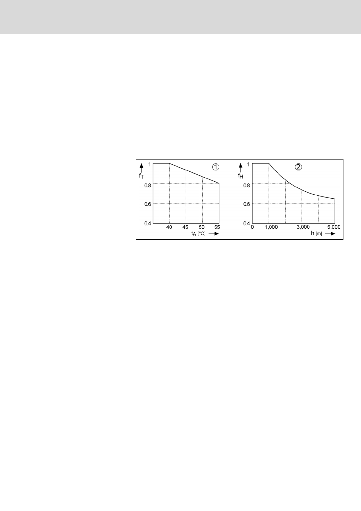
The power conductors as stated in the selection data will be reached at the
following conditions:
Ambient temperature: 0...+86.00°F
Setup elevation: 0...1,000 m above sea level
The power data is reduced according to the diagram below at deviating condi‐
tions. Do occur deviating ambient temperatures and higher setup elevations at
the same time, the power data has to be multiplied with both factors.
1 Utilization at a higher ambient temperature of more than 86.00°F.
2
Fig.5-1: Utilization at higher ambient temperature and higher setup elevation
According to DIN EN 60529-1:2000-09, the motor with mounted GTE planetary
gearbox is protected by the housing against
● contact of parts under load or moving parts
● Penetration of firm foreign bodies and water
At motors and the mounted servo gearboxes GTE the following protection class
IP 54 is valid
● for the housing of motor and gearbox
● for the output shaft of the gearbox
● for the power and encoder connection on the motor at professional mount‐
ing.
The first reference number defines the degree of protection against contact and
penetration of foreign bodies. The reference number 5 means
● Protection against penetration of dust (dust-proof)
● Complete contact protection.
The second characteristic numeral defines the degree of protection against
water. The reference number 4 means
● Protection against splashed water.
The gearboxes are surface-protected by the Citrox-method. The Citrox-method
is an environmentally-sound, thermo-chemically diffusion-method, whereby
wear behavior, corrosion-resistance and fatigue resistance of the gearbox
housing are improved.
Utilization at a higher setup elevation than 1,000 m.
Loading...