


DVR-8K
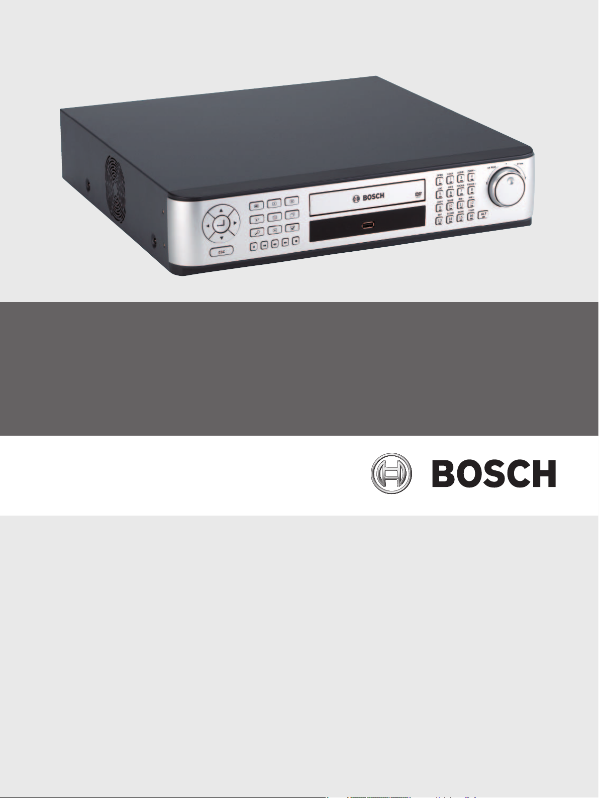
Divar MR Digital Video Recorder
Type numbers DVR-8K, DVR-16K, DVR-8L, DVR-16L
en Operation Manual_en


Digital Video Recorder Table of contents | en 1
Bosch Security Systems User Manual F01U | 2.0 | 2008.12
Table of contents
1 Safety 3
1.1 Important safety instructions 3
1.2 Safety precautions 4
1.3 Important Notices 4
2 Introduction 9
2.1 Features 9
2.2 Accessories 10
2.3 Front panel 11
2.4 Back panel 13
2.5 Remote Control 14
3 Connections and settings 17
3.1 Basic connection overview 17
3.2 Camera connections 18
3.3 Monitor connections 18
3.4 Connecting the RS-232C (COM 1) Port 18
3.5 CCTV keyboard connections 19
3.6 Network connection 19
3.7 Connecting the USB device 19
3.8 Connecting a RS-422/485 device 20
3.9 Connecting the BIPHASE port 21
3.10 Connecting the ALARM I/O port 22
3.11 System operation 23
3.12 Selecting the main monitor type 24
3.13 General explanation of the live screen on the main monitor 25
3.14 Selecting live screen mode 27
3.15 PTZ camera control 28
3.16 Viewing System Information 32
3.17 Viewing the System Log List 32
3.18 Confi guration Menu 34
3.19 Camera settings 36
3.20 Schedule settings 43
3.21 Display settings 50
3.22 Event settings 52
3.23 Network settings 55
3.24 System settings 60
4 Recording 71
4.1 Instant Recording 71
5 Search and playback 73
5.1 Playback 73
5.2 Search 73
5.3 Functions available during playback 79

2 en | Table of contents Digital Video Recorder
F01U | 2.0 | 2008.12 User Manual Bosch Security Systems
5.4 EXPORT 80
6 Control Center 83
6.1 PC minimum Requirements 83
6.2 Control Center installation 83
6.3 Connecting to the DVR 83
6.4 Main screen of DVR Control Center Program 86
6.5 Live Mode 88
6.6 Search mode 93
6.7 Remote Setup mode 97
6.8 Remote Export Settings 107
7 Additional programs 109
7.1 Alarm Notifi er program 109
7.2 Main Screen of Alarm Notifi er program 110
7.3 Archive Player program 112
7.4 Web Viewer program 115
8 REFERENCE 119
8.1 Troubleshooting 119
8.2 Recommended devices 122
8.3 Time zones 124
8.4 Factory default confi guration settings 125
8.5 Recording Time Table (500GB HDD) 128
8.6 Recording Time Table (160GB HDD) 130
8.7 Specifi cations 133

Digital Video Recorder Safety | en 3
Bosch Security Systems User Manual F01U | 2.0 | 2008.12
1 Safety
1.1 Important safety instructions
Read, follow, and retain for future reference all of the following safety instructions. Heed all
warnings on the unit and in the operating instructions before operating the unit.
1. Cleaning - Unplug the unit from the outlet before cleaning. Follow any instructions provided
with the unit. Generally, using a dry cloth for cleaning is sufficient, but a moist fluff-free cloth
or leather shammy may also be used. Do not use liquid cleaners or aerosol cleaners.
2. Heat Sources - Do not install the unit near any heat sources such as radiators, heaters,
stoves, or other equipment (including amplifiers) that produce heat.
3. Ventilation - Any openings in the unit enclosure are provided for ventilation to prevent over-
heating and ensure reliable operation. Do not block or cover these openings. Do not place the
unit in an enclosure unless proper ventilation is provided, or the manufacturer’s instructions
have been adhered to.
4. Water - Do not use this unit near water, for example near a bathtub, washbowl, sink, laun-
dry basket, in a damp or wet basement, near a swimming pool, in an outdoor installation, or
in any area classified as a wet location. To reduce the risk of fire or electrical shock, do not
expose this unit to rain or moisture.
5. Object and liquid entry - Never push objects of any kind into this unit through openings as
they may touch dangerous voltage points or short-out parts that could result in a fire or elec-
trical shock. Never spill liquid of any kind on the unit. Do not place objects filled with liquids,
such as vases or cups, on the unit.
6. Lightning - For added protection during a lightning storm, or when leaving this unit unattend-
ed and unused for long periods, unplug the unit from the wall outlet and disconnect the cable
system. This will prevent damage to the unit from lightning and power line surges.
7. Controls adjustment - Adjust only those controls specified in the operating instructions.
Improper adjustment of other controls may cause damage to the unit. Use of controls or
adjustments, or performance of procedures other than those specified, may result in hazard-
ous radiation exposure.
8. Overloading - Do not overload outlets and extension cords. This can cause fire or electrical
shock.
9. Power cord and plug protection - Protect the plug and power cord from foot traffic, being
pinched by items placed upon or against them at electrical outlets, and its exit from the unit.
For units intended to operate with 230 VAC, 50 Hz, the input and output power cord must
comply with the latest versions of IEC Publication 227 or IEC Publication 245.
10. Power disconnect - Units with or without ON/OFF switches have power supplied to the unit
whenever the power cord is inserted into the power source. The power cord is the main
power disconnect device for switching off the voltage for all units.
11. Power sources - Operate the unit only from the type of power source indicated on the label.
Before proceeding, be sure to disconnect the power from the cable to be installed into the
unit.
12. Servicing - Do not attempt to service this unit yourself. Opening or removing covers may
expose you to dangerous voltage or other hazards. Refer all servicing to qualified service per-
sonnel.
13. Damage requiring service - Unplug the unit from the main AC power source and refer servic-
ing to qualified service personnel when any damage to the equipment has occurred, such as:
– the power supply cord or plug is damaged;
– exposure to moisture, water, and/or inclement weather (rain, snow, etc.);
– liquid has been spilled in or on the equipment;
– an object has fallen into the unit;
– unit has been dropped or the unit cabinet is damaged;
– unit exhibits a distinct change in performance;
4 en | Safety Digital Video Recorder
F01U | 2.0 | 2008.12 User Manual Bosch Security Systems
– unit does not operate normally when the user correctly follows the operating instruc-
tions.
14. Replacement parts - Be sure the service technician uses replacement parts specified by the
manufacturer, or that have the same characteristics as the original parts. Unauthorized substi-
tutions could void the warranty and cause fire, electrical shock, or other hazards.
15. Safety check - Safety checks should be performed upon completion of service or repairs to
the unit to ensure proper operating condition.
16. Installation - Install in accordance with the manufacturer’s instructions and in accordance
with applicable local codes.
17. Attachments, changes or modifications - Only use attachments/accessories specified by
the manufacturer. Any change or modification of the equipment, not expressly approved by
Bosch, could void the warrantee or, in the case of an authorization agreement, authority to
operate the equipment.
1.2 Safety precautions
DANGER! High risk:
This symbol indicates an imminently hazardous situation such as
“Dangerous Voltage” inside the product.
If not avoided, this will result in an electrical shock, serious bodily
injury, or death.
WARNING! Medium risk:
Indicates a potentially hazardous situation.
If not avoided, this could result in serious bodily injury or death.
CAUTION! Medium risk:
Indicates a potentially hazardous situation.
If not avoided, this may result in minor or moderate injury.
Alerts the user to important instructions accompanying the unit.
CAUTION! Low risk: (without safety alert symbol)
Indicates a potentially hazardous situation.
if not avoided, this may result in property damage or risk of
damage to the unit.
NOTICE!
This symbol indicates information or a company policy that
relates directly or
indirectly to the safety of personnel or protection of property.
1.3 Important Notices
Accessories - Do not place this unit on an unstable stand, tripod, bracket, or mount. The unit may
fall, causing serious injury and/or serious damage to the unit. Use only with the cart, stand, tripod,
bracket, or table specified by the manufacturer. When a cart is used, use caution and care when
moving the cart/apparatus combination to avoid injury from tip-over. Quick stops, excessive force, or
uneven surfaces may cause the cart/unit combination to overturn. Mount the unit per the manufac-
turer’s instructions.
Digital Video Recorder Safety | en 5
Bosch Security Systems User Manual F01U | 2.0 | 2008.12
All-pole power switch - Incorporate an all-pole power switch, with a contact separation of at least
3 mm in each pole, into the electrical installation of the building. If it is needed to open the hous-
ing for servicing and/or other activities, use this all-pole switch as the main disconnect device for
switching off the voltage to the unit.
Battery replacement - A lithium battery is located inside the unit enclosure. To avoid danger of
explosion, replace the battery as per instructions. Replace only with the same or equivalent type rec-
ommended by the manufacturer. Dispose of the replaced battery in an environmentally friendly way.
Refer all servicing to qualified service personnel.
CAUTION!
Class I Laser Product
Invisible laser radiation when open. Avoid exposure to beam.
This warning is applicable only to those models that contain an internal DVD burner which uses a
certified Class I laser.
Coax grounding:
– Ground the cable system if connecting an outside cable system to the unit.
– Connect outdoor equipment to the unit’s inputs only after this unit has had its grounding
plug connected to a grounded outlet or its ground terminal is properly connected to a ground
source.
– Disconnect the unit’s input connectors from outdoor equipment before disconnecting the
grounding plug or grounding terminal.
– Follow proper safety precautions such as grounding for any outdoor device connected to this
unit.
U.S.A. models only - Section 810 of the National Electrical Code, ANSI/NFPA No.70, provides informa-
tion regarding proper grounding of the mount and supporting structure, grounding of the coax to
a discharge unit, size of grounding conductors, location of discharge unit, connection to grounding
electrodes, and requirements for the grounding electrode.
NOTICE!
This device is intended for use in public areas only.
U.S. federal law strictly prohibits surreptitious recording of oral
communications.
Disposal - Your Bosch product was developed and manufactured with high-quality material and
components that can be recycled and reused. This symbol means that electronic and electrical appli-
ances, which have reached the end of their working life, must be collected and disposed of sepa-
rately from household waste material. Separate collecting systems are usually in place for disused
electronic and electrical products. Please dispose of these units at an environmentally compatible
recycling facility, per European Directive 2002/96/EC.
Environmental statement - Bosch has a strong commitment towards the environment. This unit has
been designed to respect the environment as much as possible.
Electrostatic-sensitive device - Use proper CMOS/MOS-FET handling precautions to avoid electro-
static discharge.
NOTE: Wear required grounded wrist straps and observe proper ESD safety precautions when han-
dling the electrostatic-sensitive printed circuit boards.
Fuse rating - For security protection of the device, the branch circuit protection must be secured
with a maximum fuse rating of 16A. This must be in accordance with NEC800 (CEC Section 60).
Grounding and polarization - This unit may be equipped with a polarized alternating current line plug
(a plug with one blade wider than the other blade). This safety feature allows the plug to fit into
the power outlet in only one way. If unable to insert the plug fully into the outlet, contact a locally
certified electrician to replace the obsolete outlet. Do not defeat the safety purpose of the polarized
plug.
Alternately, this unit may be equipped with a 3-pole grounding plug (a plug with a third pin for earth
grounding). This safety feature allows the plug to fit into a grounded power outlet only. If unable to
insert the plug into the outlet, contact a locally certified electrician to replace the obsolete outlet.
Do not defeat the safety purpose of the grounding plug.

6 en | Safety Digital Video Recorder
F01U | 2.0 | 2008.12 User Manual Bosch Security Systems
Moving - Disconnect the power before moving the unit. Move the unit with care. Excessive force or
shock may damage the unit and the hard disk drives.
Outdoor signals - The installation for outdoor signals, especially regarding clearance from power
and lightning conductors and transient protection, must be in accordance with NEC725 and NEC800
(CEC Rule 16-224 and CEC Section 60).
Permanently connected equipment - Incorporate a readily accessible disconnect device in the build-
ing installation wiring.
Pluggable equipment - Install the socket outlet near the equipment so it is easily accessible.
Power disconnect - Units have power supplied whenever the power cord is inserted into the power
source. The power cord is the main power disconnect for all units.
Rack-mount
– Ventilation - Do not place this unit in a built-in installation or rack without proper ventilation
or adhering to the manufacturer’s instructions. The equipment must not exceed its maximum
operating temperature requirements.
– Mechanical loading - Properly mount the equipment in a rack to prevent a hazardous condi-
tion due to uneven mechanical loading.
SELV - All the input/output ports are Safety Extra Low Voltage (SELV) circuits. SELV circuits should
only be connected to other SELV circuits.
Video loss - Video loss is inherent to digital video recording; therefore, Bosch Security Systems can-
not be held liable for any damage that results from missing video information. To minimize the risk
of lost digital information, Bosch Security Systems recommends multiple, redundant recording sys-
tems, and a procedure to back up all analog and digital information.
FCC & ICES Information (residential applications)
(U.S.A. and Canadian Models Only)
This equipment has been tested and found to comply with the limits for a Class B digital device,
pursuant to part 15 of the FCC Rules. These limits are designed to provide reasonable protection
against harmful interference in a residential installation. This equipment generates, uses, and can
radiate radio frequency energy and, if not installed and used in accordance with the instructions,
may cause harmful interference to radio communications. However, there is no guarantee that inter-
ference will not occur in a particular installation. If this equipment does cause harmful interference
to radio or television reception, which can be determined by turning the equipment off and on, the
user is encouraged to try to correct the interference by one or more of the following measures:
– reorient or relocate the receiving antenna;
– increase the separation between the equipment and receiver;
– connect the equipment into an outlet on a circuit different from that to which the receiver is
connected;
– consult the dealer or an experienced radio/TV technician for help.
Intentional or unintentional modifications, not expressly approved by the party responsible for com-
pliance, shall not be made. Any such modifications could void the user’s authority to operate the
equipment. If necessary, the user should consult the dealer or an experienced radio/television tech-
nician for corrective action.
The user may find the following booklet, prepared by the Federal Communications Commission,
helpful: How to Identify and Resolve Radio-TV Interference Problems. This booklet is available from the
U.S. Government Printing Office, Washington, DC 20402, Stock No. 004-000-00345-4.
Disclaimer
Underwriter Laboratories Inc. (“UL”) has not tested the performance or reliability of the security or
signaling aspects of this product. UL has only tested fire, shock and/or casualty hazards as outlined
in UL’s Standard(s) for Safety for Information Technology Equipment, UL 60950-1. UL Certification does
not cover the performance or reliability of the security or signaling aspects of this product.
UL MAKES NO REPRESENTATIONS, WARRANTIES, OR CERTIFICATIONS WHATSOEVER REGARDING
THE PERFORMANCE OR RELIABILITY OF ANY SECURITY OR SIGNALING-RELATED FUNCTIONS OF
THIS PRODUCT.
Copyright
This user guide is the intellectual property of Bosch Security Systems and is protected by copyright.
All rights reserved.

Digital Video Recorder Safety | en 7
Bosch Security Systems User Manual F01U | 2.0 | 2008.12
Trademarks
All hardware and software product names used in this document are likely to be registered trade-
marks and must be treated accordingly.
NOTICE!
This operation manual has been compiled with great care and
the information it contains has been thoroughly verified. The text
was complete and correct at the time of printing. The ongoing
development of the products may mean that the content of the
user guide can change without notice. Bosch Security Systems
accepts no liability for damage resulting directly or indirectly from
faults, incompleteness or discrepancies between the user guide
and the product described.
More information
For additional information, please contact the Bosch Security Systems location nearest you or visit
our web site at www.boschsecurity.com

8 en | Safety Digital Video Recorder
F01U | 2.0 | 2008.12 User Manual Bosch Security Systems

Digital Video Recorder Introduction | en 9
Bosch Security Systems User Manual F01U | 2.0 | 2008.12
2 Introduction
2.1 Features
• Stable embedded operating system.
• Small fi le sizes with MPEG-4 compression.
• Internal storage capacity to 2TB.
• NTSC and PAL selectable video format.
• Full realtime recording:
- Up to 480IPS@352 X 240: DVR-16K, DVR-16L NTSC
- Up to 400IPS@352 X 288: DVR-16K, DVR-16L PAL
- Up to 240IPS@352 X 240: DVR-8K, DVR-8L NTSC
- Up to 200IPS@352 X 288: DVR-8K, DVR-8L PAL
• Various recording resolutions and quality levels:
- 4CIF (704x480), 2CIF (704x240), CIF(352x240) : NTSC
- 4CIF (704x576), 2CIF (704x288), CIF(352x288) : PAL.
- 5 step quality level (Lowest, Low, Normal, High, Best).
• Easy operation using various user interface & user friendly GUI:
- Optical mouse, Full function IR remote controller, Jog/Shuttle
• Powerful multiplex functions:
- Simultaneous live display, recording, playback, network transmission, back-up.
• Various search functions:
- Date/time search, event search, bookmark search, smart search.
• Event data protection by event partition recording.
• Pre-alarm recording (up to 1 minute).
• Motion event recording and preview test function of motion sensitivity.
• Recording image rate & quality adjustment per individual camera.
• Powerful record scheduling.
• Instant playback in live mode.
• Perfect audio/video synchronization.
• Automatic backup by schedule.
• Image authentication (Watermark).
• Three USB 2.0 ports for backup interface.
• Setup confi guration export/import with USB memory stick or network.
• Easy system software update with USB memory stick or network.
• Control Center PC software can manage max 100 DVR.
• Max fi ve clients can access one DVR server simultaneously.
• Network bandwidth throttle:
- Automatically adjust a bandwidth according to network speed status of unit.
• Remote alarm notifi cation via PC software or e-mail.
• Time and date sync from NTP server.
• Daylight saving mode.
10 en | Introduction Digital Video Recorder
F01U | 2.0 | 2008.12 User Manual Bosch Security Systems
• Covert camera protection.
• User management (User level control).
• PTZ Control:
- For more details see "8.2.4 Supported PTZ camera list".
- Dome camera telemetry control (Dome OSD control).
Note:
Model DVR-16L (16 Channel) is used for the description, operation and
details provided in this operation manual.
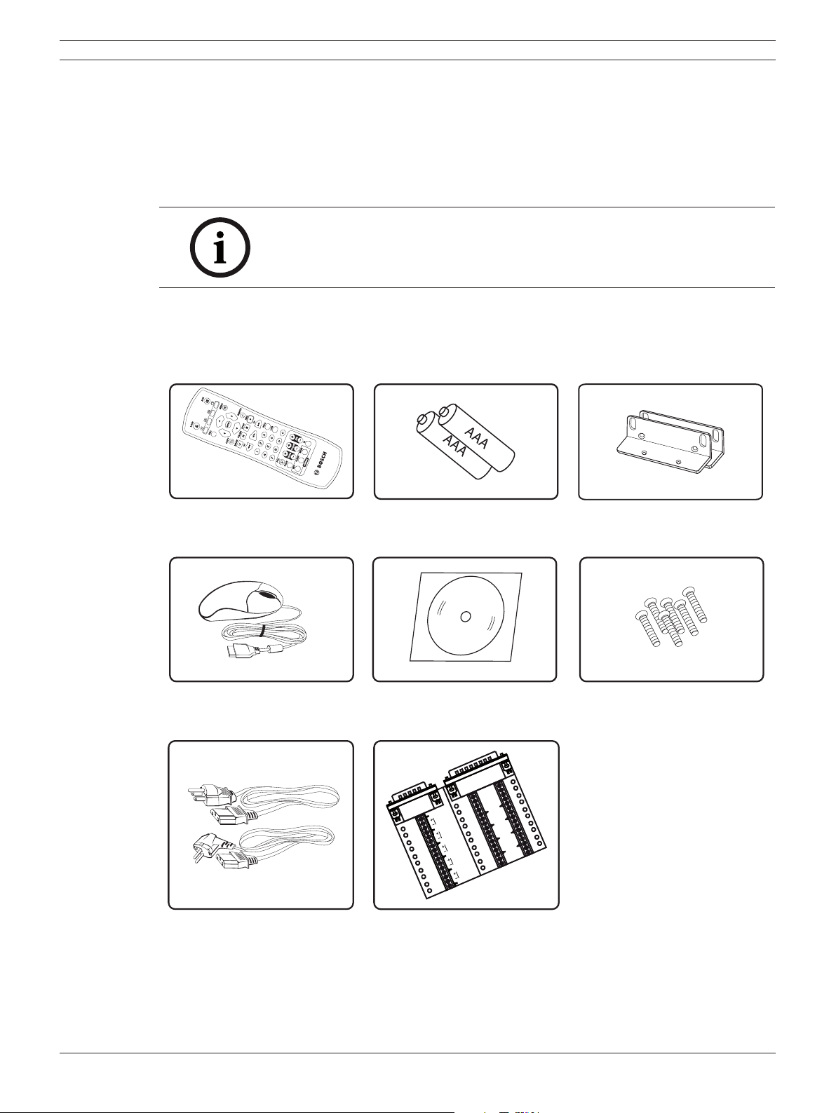
2.2 Accessories
Remote Control AAA Type Batteries for Remote
Control
Rack Mount Bracket
Mouse Divar MR PC software Screws for rack mount bracket
SHI
ELD
CTR
L
1
1A
1B
2A
2B
1
2
3
4
5
6
7
8
9
1
0
11
12
1
3
1
4
1
5
1
6
GND
GND
GND
GND
R
E
L
A
Y
3A
3B
4A
4B
SHIELD
CTRL
2
IN
IN
IN
IN
SHI
ELD
CTR
L 3
SHI
ELD
CTR
L
4
SHI
ELD
SHI
ELD
CTR
L
5
Power plugs Connection board for Alarm I/O
and Biphase
Figure 2.1 Accessories
Digital Video Recorder Introduction | en 11
Bosch Security Systems User Manual F01U | 2.0 | 2008.12
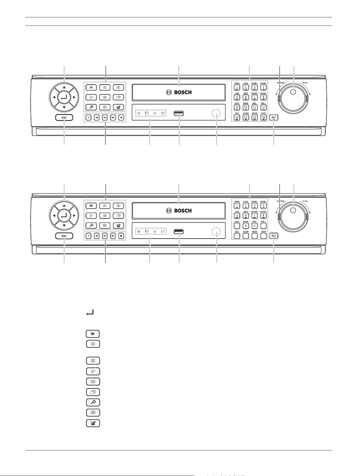
2.3 Front panel
DVR-16K / DVR-16L
ab c def
gh ijk l
DVR-8K / DVR-8L
ab c def
gh ijk l
Figure 2.2 Front panel
a Arrow Buttons (b B v V): Select or move between the menu options.
(ENTER): Confi rms menu selections.
b Function Buttons
: Displays the setup menu.
: Display the monitor A control menu to set the screen mode to full, 4, 6, 8, 9 or 16
screens. Set the video output signal to VGA mode.
: Display the monitor B control menu. Set the video output signal to MON A mode.
: Switches the unit to PTZ mode to control the connected PTZ camera.
: Press to see different multiscreen modes.
: View all channels in sequence.
: Displays the search menu.
: Starts or stops instant recording of the selected camera (yellow border).
: Cancels alarm activation and returns the system to the condition before the alarm was
activated.

12 en | Introduction Digital Video Recorder
F01U | 2.0 | 2008.12 User Manual Bosch Security Systems
c Disc Tray (DVR-8L and DVR-16L only)
Insert a disc here.
d Channel Buttons
You can input a number with the channel buttons. You can also use the channel buttons for
sub-function with ALT button (The COPY, IRIS +, SET, CLEAR, MOVE and TOUR buttons of 8
channel DVR are used for subfunction without ALT button.).
• The LED in the button indicates the status as follows:
- Off: The current status is for live mode.
- Red: Recording mode.
Blinks when an event occurs.
• (1) OPEN: Opens or closes the disc tray (DVR-8L and DVR-16L only).
• (2) LOCK: Displays the lock menu to change the user type or disable the system
operation.
• (3) ZOOM - / (4) ZOOM +: Adjusts the zoom level of the PTZ camera.
• (5) LOG: Displays or removes the System Log List.
• (6) INFO: Displays or removes system information.
• (7) FOCUS - / (8) FOCUS +: Adjusts focus position of the PTZ camera.
• (9) COPY: Copies the recording data to an external device.
• (10) MARK: Sets the mark point for recording search. You can set the mark point during
the single channel playback of recorded data.
• (11) IRIS - / (12) IRIS +: Adjusts iris position of the PTZ camera.
• (13) SET: Registers the PTZ camera's preset position.
• (14) CLEAR: Deletes a memorized preset position of the PTZ camera.
• (15) MOVE: Moves the PTZ camera to the preset position.
• (16) TOUR: Tours all registered preset positions in the PTZ camera.
e Shuttle Ring: Fast forward or reverse picture search when the dial is rotated.
f JOG Dial: Allows a forward or reverse frame search.
In pause mode, plays recorded images frame by frame through rotation. Increases or
decreases the options value.
g ESC: Use to return to previous level or to exit menu system without saving.
h Playback Control Buttons
- X: Pauses playback.
- m: Reverse search the recorded images.
- bB: Playback or reverse playback of recorded images.
- M: Forward search the recorded images.
- x: Stops playback.
i Indicators
: Lights when the DVR is powered.
: Blinks when the HDD is accessed.
: Lights when the alarm is active.
: Lights when a network cable is connected.
j USB Port
Connect an external USB device for back up or playback.
k Remote Sensor
Point the remote control here.
l ALT
Activate if you use the Sub-function of the channel button.
Digital Video Recorder Introduction | en 13
Bosch Security Systems User Manual F01U | 2.0 | 2008.12
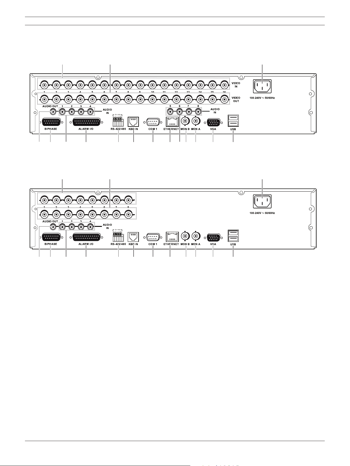
2.4 Back panel
DVR-16K / DVR-16L
ab c
de f g h i j kflm n o
DVR-8K / DVR-8L
ab c
de f g h i j k lm n o
Figure 2.3 Back panel
a VIDEO INPUT: Connect the camera’s video output to these BNC connectors.
b LOOP OUT: The signal from VIDEO INPUT connector is looped out to this connector.
c Power Cord Inlet (AC IN): Connect the power plug.
d AUDIO OUT: Connect the audio input signal of an external device.
e BIPHASE: Connect a pan/tilt/zoom control unit via the supplied 15-pole D-type connector
board.
f AUDIO IN: Connect the audio output of an external device.
g ALARM I/O: Connect up to 16 alarm inputs via the supplied 25-pin D-type connector board.
Connect up to 8 alarm output relays via the supplied 25-pin D-type connector board.
h RS-422/485 Terminals: Connect RS422/485 compatible cameras.
i KBD IN: Connect a Bosch CCTV keyboard unit to the KBD IN socket.
j COM1: Use to connect to a host device equipped with RS-232C connector (such as a personal
computer).
k ETHERNET Port: Connect the ethernet 10/100Mbps network cable for controlling this unit via
a PC network.
l MON B (BNC Type Connector): Connect to spot monitor or display device.
14 en | Introduction Digital Video Recorder
F01U | 2.0 | 2008.12 User Manual Bosch Security Systems
m MON A (BNC Type Connector): Connect to main monitor or display device.
n VGA: Connect a VGA monitor.
o USB Ports: Connect optional extension USB devices (e.g. mouse, memory stick).
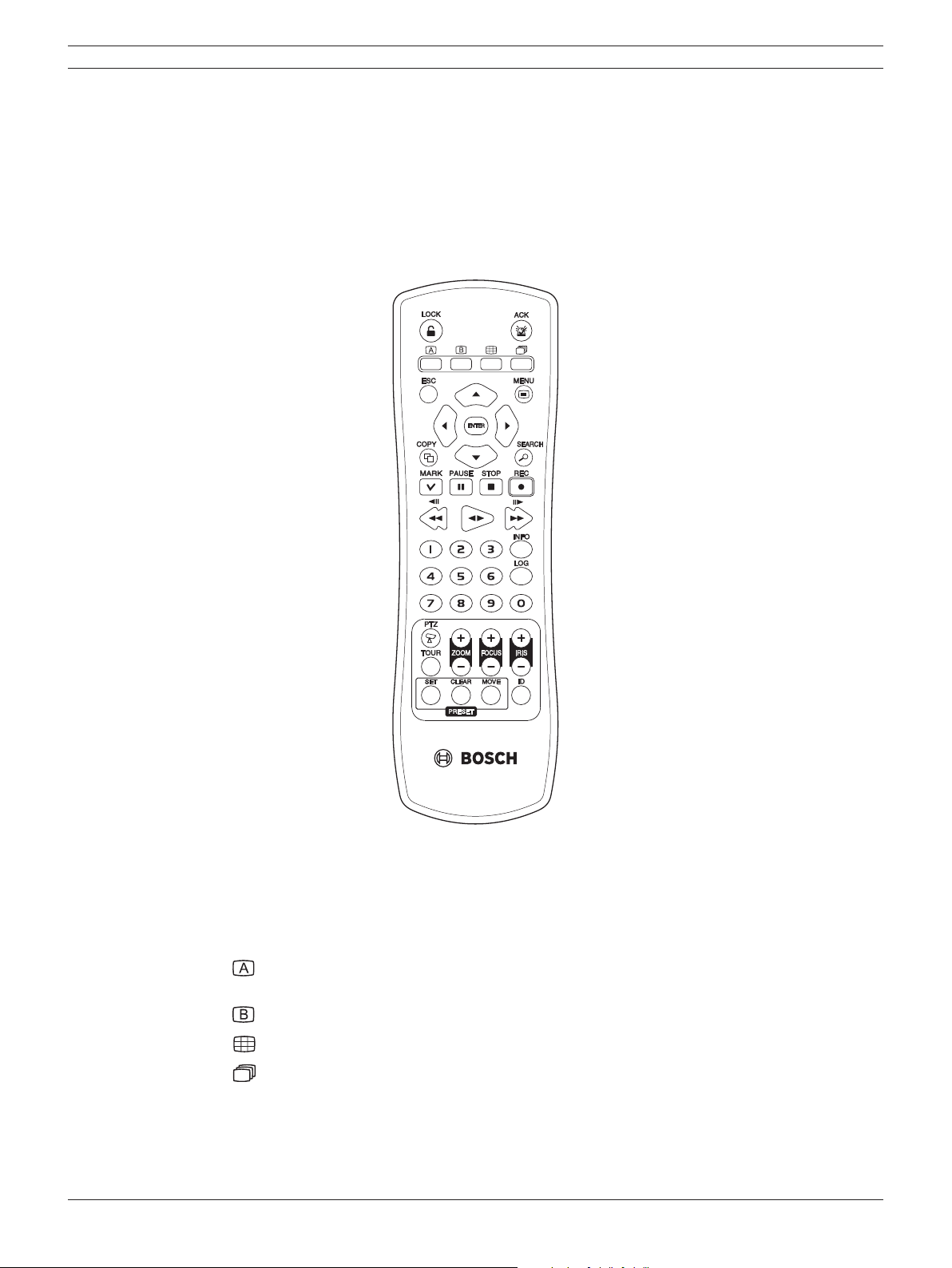
2.5 Remote Control
Figure 2.4 Remote control.
• LOCK: Displays the lock menu to change user type or disable system operation.
• ACK: Cancels alarm activation and returns the system to the condition before the alarm was
activated.
•
: Display the monitor A control menu to set the screen mode to full, 4, 6, 8, 9 or 16
screens.
•
: Display the monitor B control menu to allow spot monitor control.
•
: Press to see different multiscreen modes.
•
: View all channels in sequence.
• ESC: Use to return to previous level or to exit menu system without saving.
• MENU: Displays the setup menu.
• Arrow Buttons (b B v V): Selects or moves between the menu options.

Digital Video Recorder Introduction | en 15
Bosch Security Systems User Manual F01U | 2.0 | 2008.12
• ENTER: Confi rms menu selections or go to full screen of a selected camera in multiscreen.
Pressing this key again to return from full screen to multiscreen.
• COPY: Copies the recorded data to an external device.
• SEARCH: Displays the search menu.
• MARK: Sets the mark point for recording search. You can set the mark point during the single
channel playback of recorded data.
• PAUSE (X): Pauses playback.
• STOP(x): Stops playback.
• REC (z): Starts or stops recording.
• m / c: Reverse search; Searches the recorded images in reverse sequence.
• bB: Playback or reverse playback of recorded images.
• M / C: Forward search; Searches the recorded images in forward sequence.
• Number Buttons (0, 1-9): To select the PTZ preset number, ID, or channel.
• INFO: Displays or removes the system information window.
• LOG: Displays or removes the System Log List window.
• PTZ: Switches this unit to PTZ mode to control the connected PTZ camera.
• TOUR: Tours all registered preset positions in the PTZ camera.
• ZOOM + / -: Adjusts the zoom level of the PTZ camera.
• FOCUS + / -: Adjusts the focus of the PTZ camera.
• IRIS + / -: Adjusts the iris of the PTZ camera.
• PRESET
- SET: Registers the PTZ camera’s preset positions.
- CLEAR: Deletes a memorized preset position.
- MOVE: Moves the camera to the preset position.
• ID: Set the appropriate DVR system ID to operate via the IR Remote Controller when using
multiple DVRs. Press the ID button, then press the number button within 2 seconds to select
the system ID of the DVR. If you set the system ID to “0”, you can control multiple DVR at the
same time.

16 en | Introduction Digital Video Recorder
F01U | 2.0 | 2008.12 User Manual Bosch Security Systems
Digital Video Recorder Connections and settings | en 17
Bosch Security Systems User Manual F01U | 2.0 | 2008.12
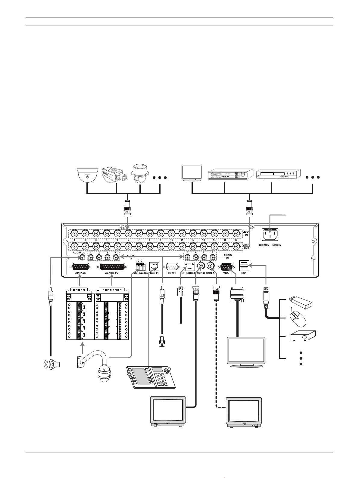
3 Connections and settings
Precautions
• There are various ways to connect the unit, depending on the camera and other equipment.
Please refer to the camera manual or the manuals for other devices as necessary for additional
connection information.
• Be sure to switch off the camera before installation and connection.
•
Default the main monitor (MON A) will start up in VGA mode. See section 3.12 for selection
of the main monitor type.
3.1 Basic connection overview
SHIELD
CTRL 1
1A
2A
3A
4A
1
2
3
4
5
6
7
8
9
10
11
12
13
14
15
16
GND
GND
GND
GND
R
E
L
A
Y
5A
6A
7A
8A
SHIELD
CTRL 2
IN
IN
IN
IN
SHIELD
CTRL 3
SHIELD
CTRL 4
SHIELD
SHIELD
CTRL 5
ab
c
e
d
fgh
i
j
k
l
m
n
Figure 3.1 Basic connection overview

18 en | Connections and settings Digital Video Recorder
F01U | 2.0 | 2008.12 User Manual Bosch Security Systems
a Connect the cameras to the BNC loop-through camera inputs (automatically terminated).
b Connect the Monitor, DVR, VCR, or others to the video out BNC.
c Connect the power cord to the unit.
d Connect an audio amplifi er.
e Connect a pan/tilt/zoom control unit via the supplied 15-pole D-type connector board.
f Connect up to 16 (alarm) inputs or connect up to 8 alarm output relays via the supplied 25-pin
D-type connector board.
g Connect PTZ cameras or DVRs.
h Connect a Bosch CCTV keyboard unit to the KBD IN socket.
i Connect audio (line input).
j Connect to your network via the Ethernet port or use the RS232 connector to connect directly
to a PC serial port (for service purposes).
k Connect monitor B to the BNC output MON B.
l Connect monitor A to the BNC output MON A.
m Connect a VGA monitor.
n Connect optional extension USB devices (e.g. mouse, memory stick).
3.2 Camera connections
Connect cameras to the unit using 75-ohm video coaxial cables with BNC connectors. There are
two BNC connectors for each camera. Either connector can receive a camera’s signal. This signal
is looped-through (directly connected) to the other connector, so that you can send the camera’s
signal to other equipment. The camera input connectors are auto-terminating, so you do not need to
add a terminator to the output connector if no additional equipment is connected.
If the camera signal is looped-through to additional equipment, make sure that the end of the video
line is terminated with a 75-ohm terminator.
3.3 Monitor connections
Connect the unit to the monitors via 75-ohm video coaxial cables with BNC connectors. The unit
provides a 1Vpp CVBS signal.
If the monitor has a loop-through connection and you are not using the loopthrough output, then
select the 75-ohm impedance setting on the monitor. If the monitor’s loop-through output is
connected to an additional device, the device’s termination is set to 75 ohms and the monitor’s
termination is set to high impedance (note that this is not necessary on devices with automatic
termination).
3.4 Connecting the RS-232C (COM 1) Port
The serial RS232 console port connector is used to connect a PC to the unit for service purposes.
Use a null-modem cable to connect the serial port of the PC to the unit.
This terminal is compliant with the RS-232C standard.

Digital Video Recorder Connections and settings | en 19
Bosch Security Systems User Manual F01U | 2.0 | 2008.12
3.5 CCTV keyboard connections
The keyboard input connector is used to connect an external CCTV keyboard to the unit. Connect
the keyboard to the KBD IN connector.
For short distances (up to 30m), standard 6-core telecom flat cable can be used to supply power
and signal connections for the keyboard.
For distances over 30m between keyboard and Divar MR, the Keyboard Extension Kit (LTC 8557)
must be used. This kit provides junction boxes, cables and the appropriate power supply for the
external keyboards. The recommended cable type is Belden 9841 or equivalent.
3.6 Network connection
3.6.1 LAN connection
Connect the LAN port to an available 10/100 base-T port with a straight ethernet cable (not
supplied).
3.6.2 Automatic network configuration
The DVR can automatically obtain and configure the network interface via DHCP.
3.6.3 Manually configure network
The DVR may be manually configured by assigning an IP address, subnet mask, gateway and DNS.
3.7 Connecting the USB device
3.7.1 USB memory device
Insert the memory device into the USB port. The system automatically recognizes the device.
Using a USB memory device the system software can be easily upgraded.
3.7.2 USB backup device
Connect the USB cable of the USB backup device to the USB port on the rear panel of the unit.
(Example: HDD or other external storage).
3.7.3 Mouse
Connect the USB mouse for function control of the unit.
20 en | Connections and settings Digital Video Recorder
F01U | 2.0 | 2008.12 User Manual Bosch Security Systems
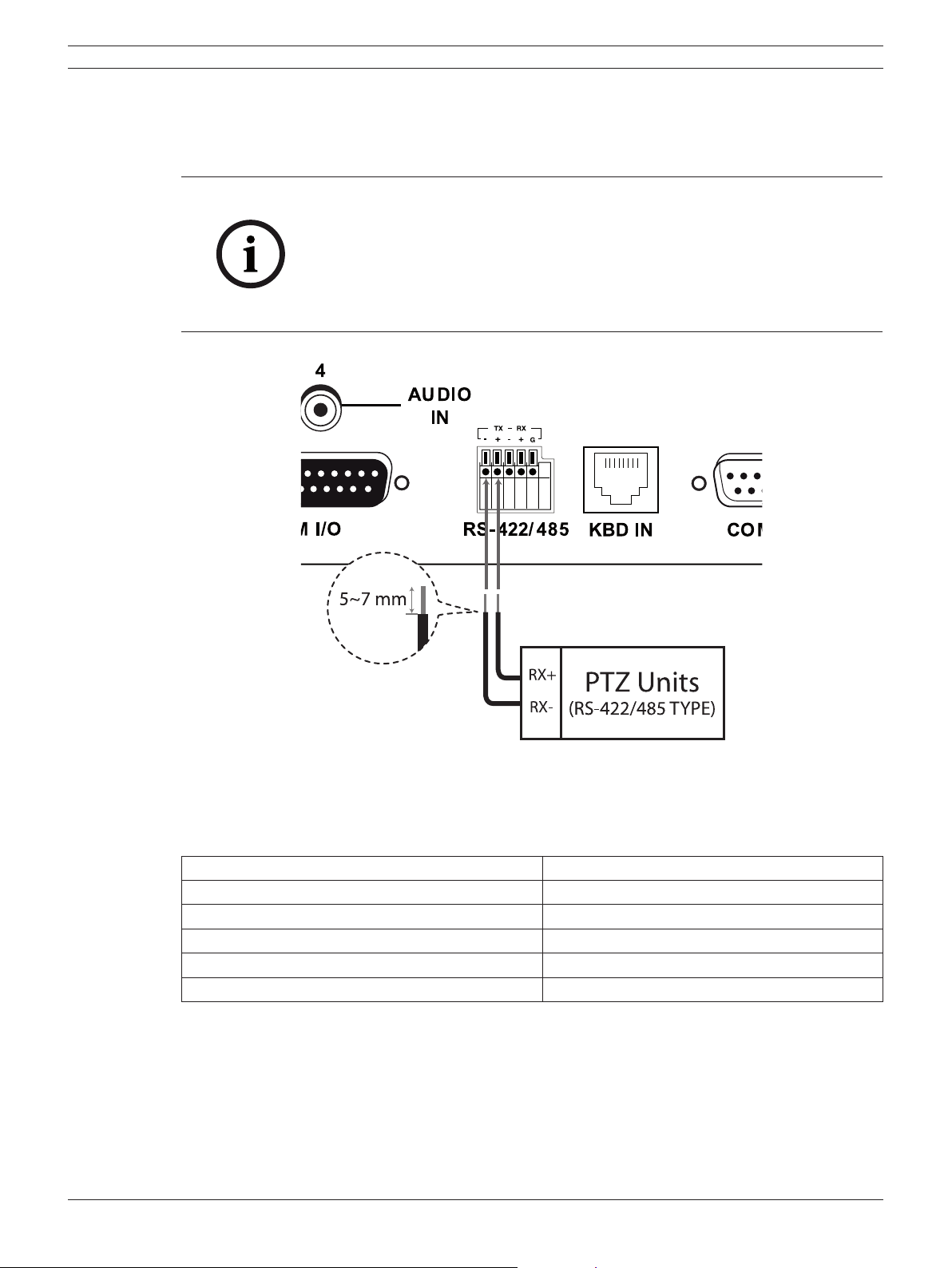
3.8 Connecting a RS-422/485 device
Use this port to connect PTZ cameras.
Connect the PTZ serial communication lines to the RS-422/485 terminal.
Notes:
• When connecting lines, connect the TX- of the DVR to RX- of the PTZ
unit and TX+ of the DVR to RX+ of the PTZ unit correctly.
• Recommended initial data are 9600 Baud Rate, 8 Data bits, 1 Stop bit
and No parity.
• When connecting PTZ cameras to DVRs it is necessary to set the setup
menu for this unit according to the RS-485 settings of the camera and
DVRs.
Figure 3.2 RS-422/485 connections
RS-422/485 Terminal Description
TX- (DATA -) Data Transmission
TX+ (DATA +) Data Transmission
RX- (DATA -) Data Reception
RX+ (DATA +) Data Reception
GND Shield
Table 3.1 RS-422-485 connections
Digital Video Recorder Connections and settings | en 21
Bosch Security Systems User Manual F01U | 2.0 | 2008.12
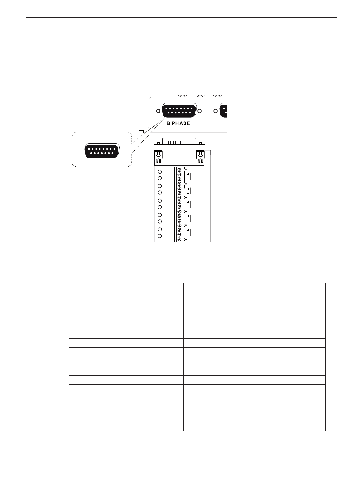
3.9 Connecting the BIPHASE port
The Biphase port is used for connecting cameras that use Bosch Biphase communications to
control camera positioning. Five Biphase outputs are provided for dome camera and pan, tilt and
zoom control. The screw terminal connection board supplied with the unit simplifies all Biphase
connections to the unit.
Maximum cable length per Biphase output is 1.5 kilometers (0.9 miles). Maximum number of
controllable cameras is 4 per Biphase output.
1
8
9
15
SHIELD
CTRL 1
SHIELD
CTRL 2
SHIELD
CTRL 3
SHIELD
CTRL 4
SHIELD
SHIELD
CTRL 5
Figure 3.3 Biphase port connector
BIPHASE port - 15-pole D-type socket
Signal name: Pin no. Description
Code 1 - 1 Biphase control ch. 1 (minus)
Code 1 + 2 Biphase control ch. 1 (plus)
Shield 3 System ground/cable shield.
Code 2 - 4 Biphase control ch. 2 (minus)
Code 2 + 5 Biphase control ch. 2 (plus)
Shield 6 System ground/cable shield.
Code 3 - 7 Biphase control ch. 3 (minus)
Code 3 + 8 Biphase control ch. 3 (plus)
Shield 9 System ground/cable shield.
Code 4 - 10 Biphase control ch. 4 (minus)
Code 4 + 11 Biphase control ch. 4 (plus)
Shield 12 System ground/cable shield.
Code 5 - 13 Biphase control ch. 5 (minus)
Code 5 + 14 Biphase control ch. 5 (plus)
Shield 15 System ground/cable shield.
Table 3.2 Biphase pin configuration
22 en | Connections and settings Digital Video Recorder
F01U | 2.0 | 2008.12 User Manual Bosch Security Systems
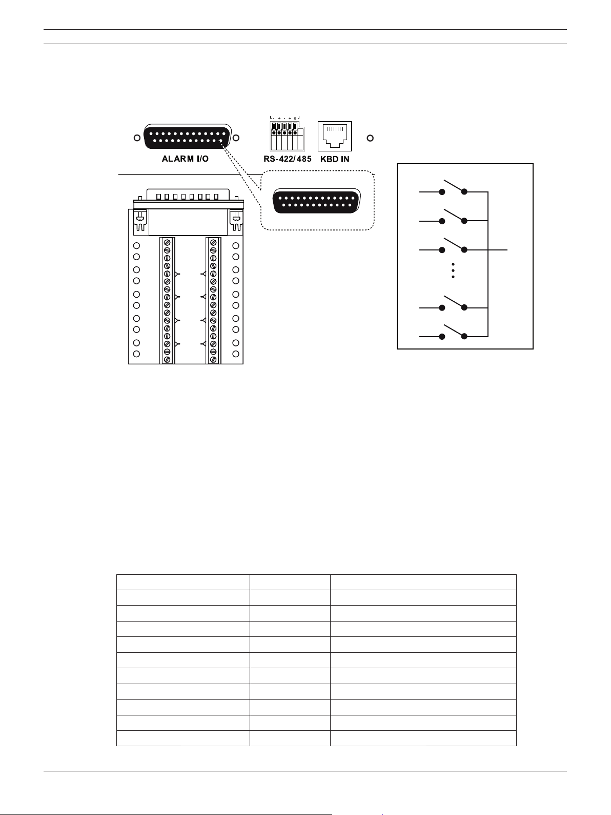
3.10 Connecting the ALARM I/O port
Alarm inputs and outputs are supplied via a 25-pole D-type socket. The screw terminal input/output
connection board supplied with the unit simplifies all alarm connections to the unit.
1
13
14
25
1A
2A
3A
4A
1
2
3
4
5
6
7
8
9
10
11
12
13
14
15
16
GND
GND
GND
GND
R
E
L
A
Y
5A
6A
7A
8A
IN
IN
IN
IN
1A
Relay 1
GND
2A
3A
7A
Relay 2
Relay 3
Relay 7
Relay 8
8A
Figure 3.4 Alarm I/O port connector
3.10.1 Connecting the Inputs
Each (alarm) input line can be switched by a relay contact from devices such as pressure pads,
passive infra red detectors, smoke detectors and similar devices.
Wire them as either N/O (Normally Open) or N/C (Normally Closed). You can configure the alarm
inputs as N/O or N/C in the menu system. The default is N/O.
3.10.2 Connecting the Alarm Outputs
The eight alarm output relays respond to input alarms and triggers. You can configure the alarm
outputs as N/O or N/C in the menu system. The relays are active for the duration of the driving
event. Connect the application to the alarm output relays (resistive loads only). Do not exceed 1A
30V DC, 0.3A 125V AC on an alarm output relay’s contacts. The contacts must not be used at AC line
voltages.
ALARM I/O - 25-pole D-type socket
Signal name Pin no. Description
Alarm_in_1 1 Alarm input 1
Alarm_in_2 2 Alarm input 2
Alarm_in_3 3 Alarm input 3
Alarm_in_4 4 Alarm input 4
Alarm_in_5 5 Alarm input 5
Alarm_in_6 6 Alarm input 6
Alarm_in_7 7 Alarm input 7
Alarm_in_8 8 Alarm input 8
Alarm_in_9 9 Alarm input 9
Alarm_in_10 10 Alarm input 10
Digital Video Recorder Connections and settings | en 23
Bosch Security Systems User Manual F01U | 2.0 | 2008.12
Alarm_in_11 11 Alarm input 11
Alarm_in_12 12 Alarm input 12
Alarm_in_13 13 Alarm input 13
Alarm_in_14 14 Alarm input 14
Alarm_in_15 15 Alarm input 15
Alarm_in_16 16 Alarm input 16
Relay1_A 17 Relay 1 output pole 1
Relay2_A 18 Relay 2 output pole 1
Relay3_A 19 Relay 3 output pole 1
Relay4_A 20 Relay 4 output pole 1
Relay5_A 21 Relay 5 output pole 1
Relay6_A 22 Relay 6 output pole 1
Relay7_A 23 Relay 7 output pole 1
Relay8_A 24 Relay 8 output pole 1
System Ground 25 Chassis Ground
Table 3.3 Alarm I/O pin confi guration
3.11 System operation
Default monitor setting is VGA.
1. Turn on the unit. System booting will commence. The BOSCH logo image will be displayed on
the main monitor during the system booting.
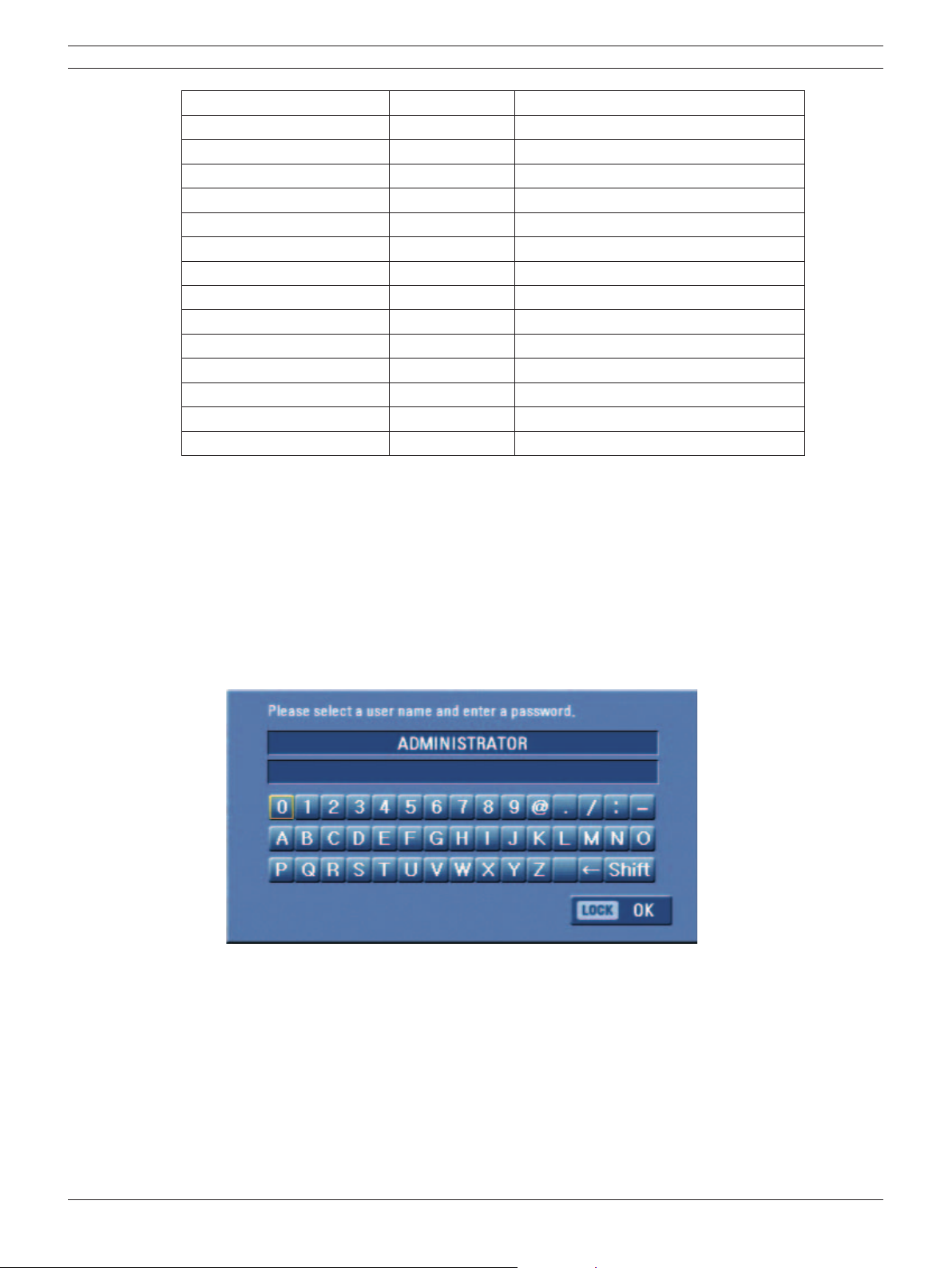
2. When booting is complete, the login window will be displayed.
Select a user ID by using the mouse or arrow, then the ENTER button on the remote control or
front panel.
Figure 3.5 Login window
- ADMINISTRATOR: Unlimited operation of the unit.
- Advanced User: Use of the limited functions of the system (the setup confi guration is not
allowed to change).
- Normal User: Use of the limited functions of the system (multiscreen monitor and live
image view are available).
3. Enter the password by using the virtual keyboard. (Initial password is “000000”.)
4. Press LOCK or click the OK (LOCK) icon.
You can see the live screen and operate the system.
24 en | Connections and settings Digital Video Recorder
F01U | 2.0 | 2008.12 User Manual Bosch Security Systems
• It is not possible to connect the VGA monitor and the composite monitor simultaneously.
Consequently, the user is obliged to choose either the composite monitor or the VGA monitor.
When set to composite monitor there is no VGA output. When set to VGA monitor there is no
composite output. Monitor B is unaffected by the monitor setting.
• This DVR is based on a VGA monitor using OSD. We recommend using the VGA monitor with
this unit. If you use a composite monitor, the OSD quality may lower to read it.
• User access rights:
User Level Administrator Advanced User Normal User
View Live Video YES YES YES
Alarm Off YES YES NO
PTZ YES YES NO
Instant Record YES YES NO
Export YES YES NO
Search/Play YES YES NO
Setup YES NO NO
Table 3.4 User access rights
3.12 Selecting the main monitor type
You can select the main monitor type to display the main screen during power on.
3.12.1 Using the VGA monitor
1. Connect the VGA monitor to the VGA connector on the back of the DVR.
2. Turn on the VGA monitor.
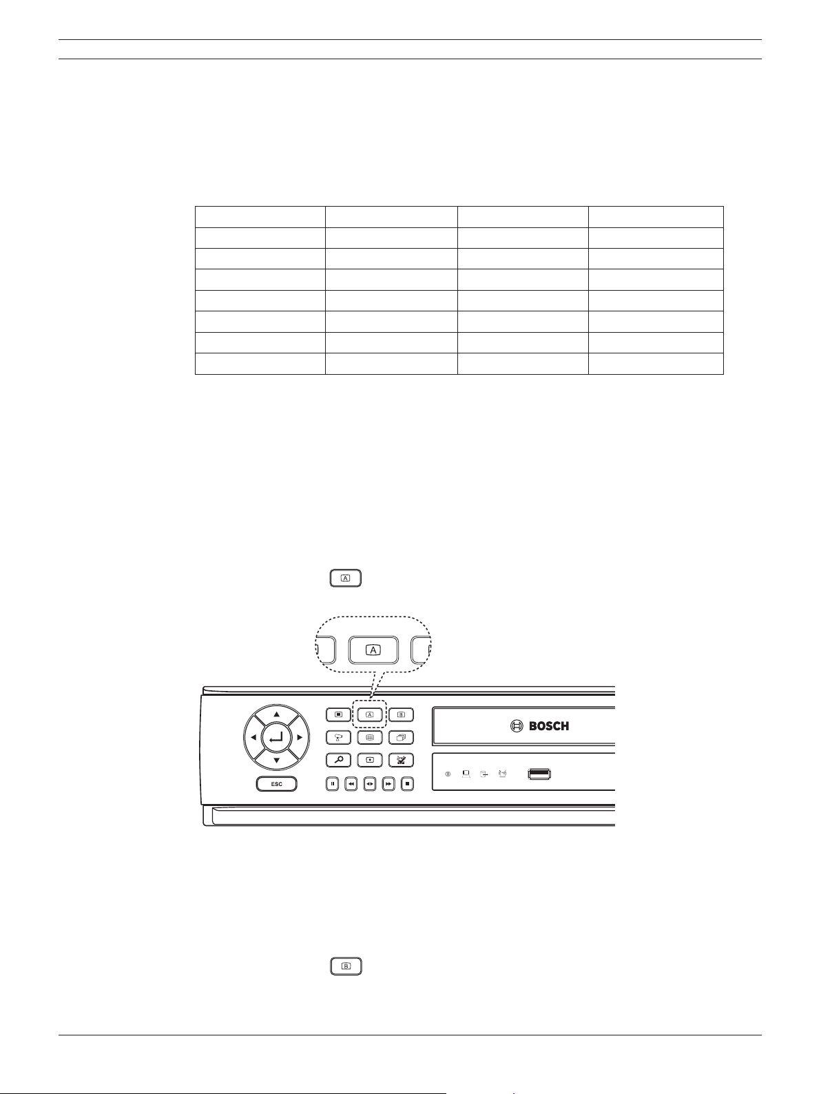
3. Press and hold the A (
) button on the front panel until the beep sounds to display the
main screen. The DVR will restart and then the VGA monitor is set as a main monitor.
Figure 3.6 The A button on the front panel
3.12.2 CCTV (composite video type) monitor
1. Connect the CCTV monitor to the MON A connector on the back of the DVR.
2. Turn on the CCTV monitor.
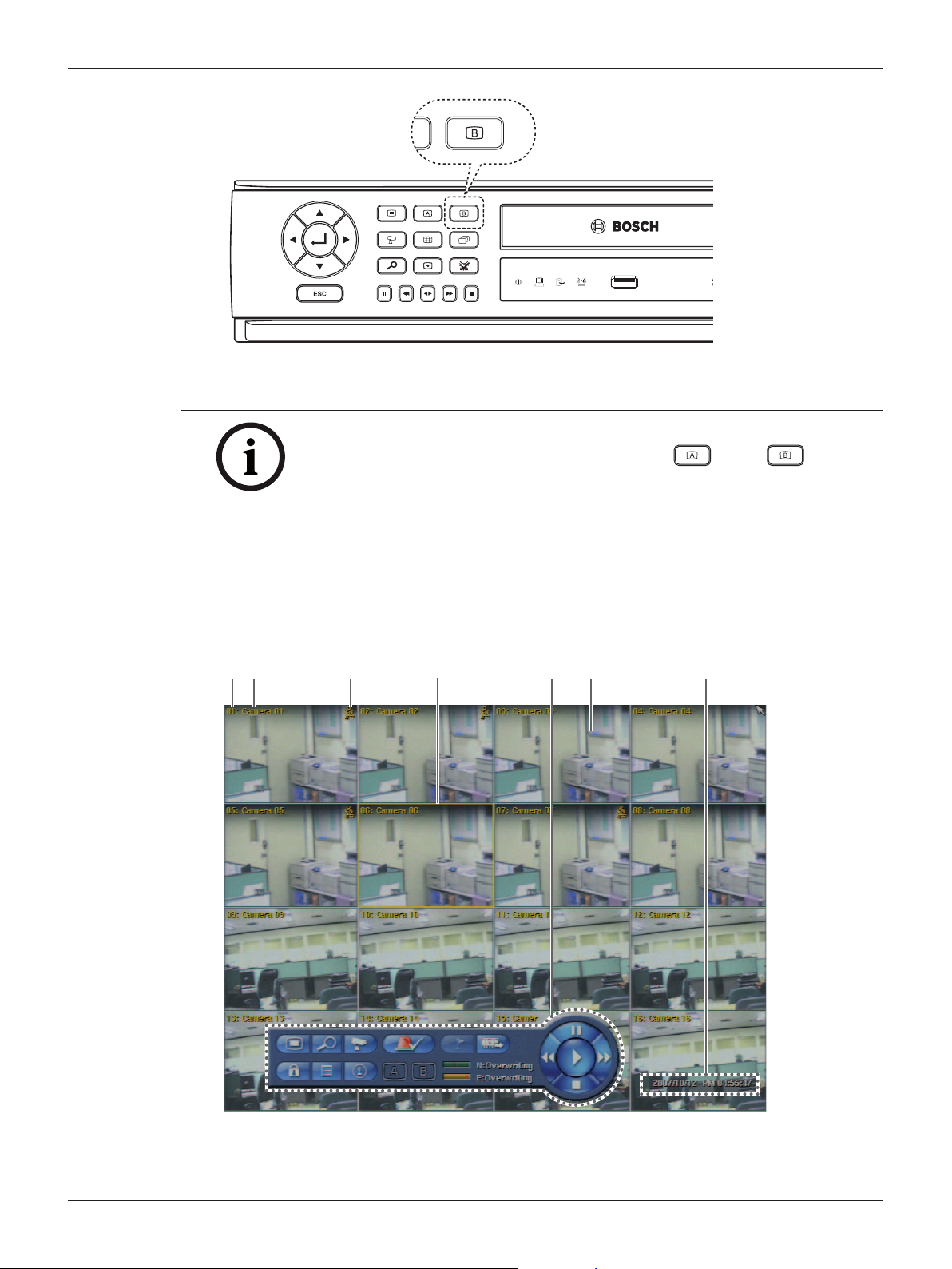
3. Press and hold the B (
) button on the front panel until the beep sounds to display the
main screen. The DVR will restart and the CCTV monitor is then set as main monitor.
Digital Video Recorder Connections and settings | en 25
Bosch Security Systems User Manual F01U | 2.0 | 2008.12
Figure 3.7 The B button on the front panel
Note:
You can select the monitor type by using the A ( ) or B ( ) button
at any time. If you change the monitor type, the system will be rebooted
automatically.
3.13 General explanation of the live screen on the main monitor
Main monitor screen
ab c d e f g
Figure 3.8 Main monitor screen
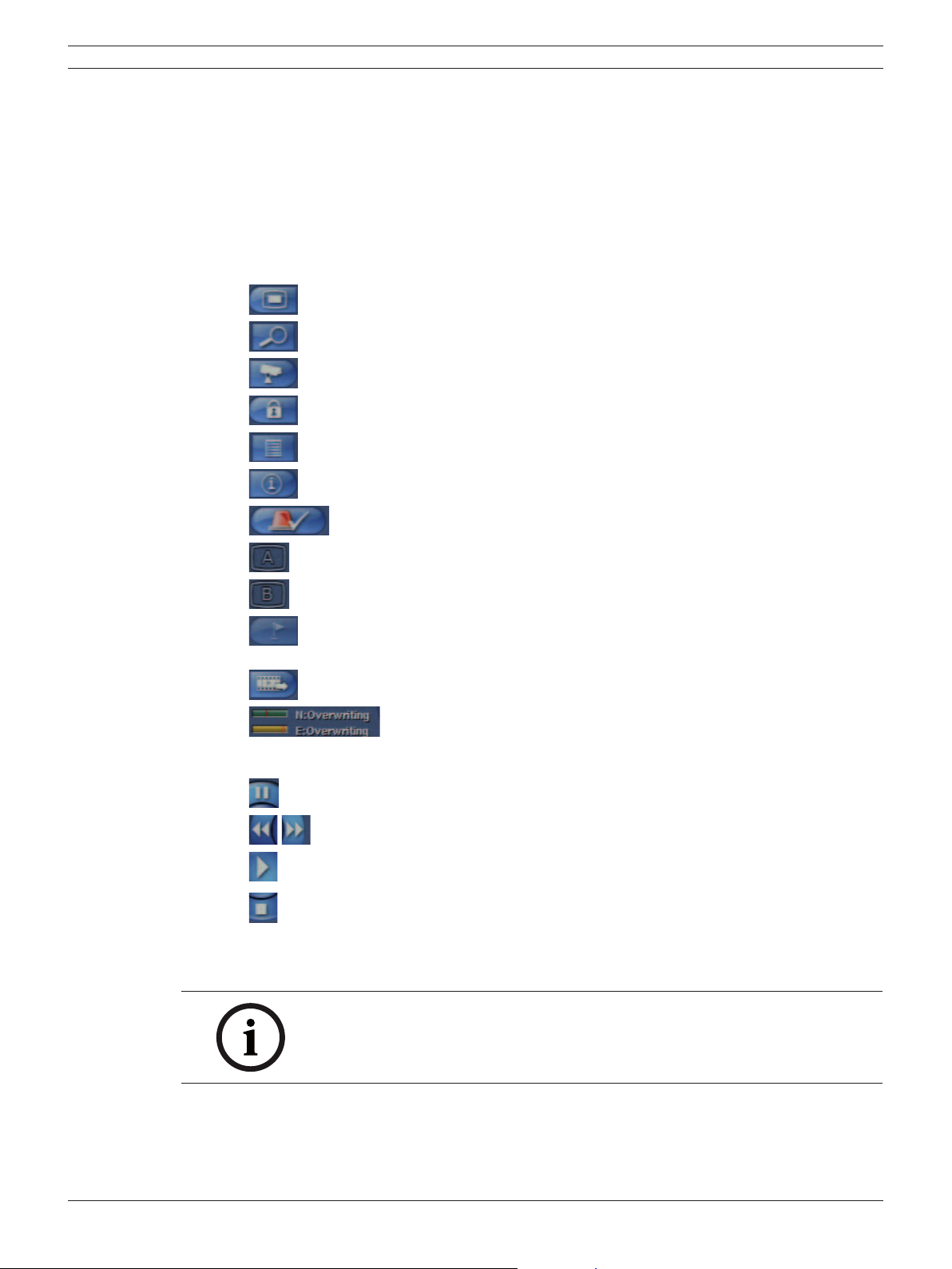
26 en | Connections and settings Digital Video Recorder
F01U | 2.0 | 2008.12 User Manual Bosch Security Systems
a Channel Number: Displays the channel number.
b Camera Name: Displays the edited camera name.
c Recording status icon: Displays the recording status.
• Red “Dot icon” indicates Instant recording.
• Yellow “Running man icon” indicates motion detection recording.
• Red “Alarm bell icon” indicates input triggered recording.
d Selected Channel: Displays the selected channel with yellow box.
e System Control Bar
•
: Displays the setup menu.
•
: Displays the search menu.
•
: Displays the PTZ remote control window.
•
: Displays the lock menu to change the user type or disable system operation.
•
: Displays the system log list window.
•
: Displays the system information window.
•
: Turns the alarm off.
•
: Displays the screen division selection window for the monitor A.
•
: Displays the screen division selection window for the monitor B.
•
: Click at a desired point to be marked during playback. Up to 15 points can be
marked.
•
: Display copy (export) menu.
•
:Displays the remaining HDD status.
- N (Normal partition): Used size/total size.
- E (Event partition): Used size/total size.
•
: Pause playback.
•
: Select the required scanning speed.
•
: Starts instant playback in selected channel.
•
: Stop playback.
f Live Screen: Displays the current surveillance live screen.
g Displays the current date and time.
Note:
Click the right button on the mouse to display / remove the system control
bar displayed on-screen.
Digital Video Recorder Connections and settings | en 27
Bosch Security Systems User Manual F01U | 2.0 | 2008.12
3.14 Selecting live screen mode
3.14.1 Monitor A
You can select the live screen mode to display a full, 4-view, 6-view, 8-view, 9-view or 16-view
screens on the main monitor.
1. Press A (
) button or click the icon in the system control bar.
The screen mode select menu of monitor A is displayed on the monitor A.
2. Select screen mode.
ab cde
Figure 3.9 The screen mode select menu of monitor A.
a Selected channel of the monitor A.
b Channel buttons: Press the 1 to 16 channel button to see the current camera images in
selected live screens on the monitor A.
c Screen mode
• Full Screen Mode: When you see the selected channel on the full screen.
• 4, 6, 8, 9 and 16 view Mode: Displays selected multi screens on the monitor A.
d Selected view mode.
e Sequence: Views the all channels in sequence.
3. Select [OK (A)] and press ENTER to confi rm your selection.
Note:
To display the screen you desire to watch in full screen mode, double click
the desired channel.
28 en | Connections and settings Digital Video Recorder
F01U | 2.0 | 2008.12 User Manual Bosch Security Systems
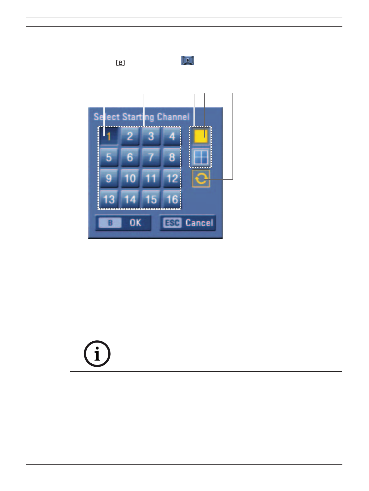
3.14.2 Monitor B
You can select the live screen mode to full or 4-view screens on the monitor B.
1. Press B (
) button or click the icon in the system control bar.
The screen mode select menu of monitor B is displayed on the monitor A.
2. Select screen mode.
ab cde
Figure 3.10 The screen mode select menu of monitor B.
a Selected channel of the monitor B.
b Channel buttons: Press a 1 to 16 channel button to see the current camera image on the
monitor B.
c Screen mode
• Full Screen Mode: When you see the selected channel on the full screen.
• 4 view Mode: Displays 4 view screens on the monitor B.
d Selected view mode.
e Sequence: View all channels in sequence.
3. Select [OK (B)] and press ENTER to confi rm your selection.
Note:
On Monitor B output always the channel number (CH01 ... CH16) is
displayed. Camera name can only be displayed on Monitor A output.
3.15 PTZ camera control
You can control the cameras connected via the biphase port and data port RS-422/485 terminal. You
must set the configuration between the PTZ camera and the DVR.
1. Select the PTZ camera channel on monitor A you want to control.
2. Press PTZ or click the PTZ icon in the system control bar.
PTZ virtual remote control is displayed on monitor A.
3. Use each item to control the PTZ camera.
 Loading...