


DVR-650-16A
Table of contents
 Loading...
Video Recorder 630/650 Series
DVR 630/650 Series
en Installation and Operation manual


Video Recorder 630/650 Series Table of Contents | en 3
Table of Contents
1Safety 7
1.1 Safety precautions 7
1.2 Important safety instructions 7
1.3 Important Notices 9
1.4 FCC and UL 11
1.5 Bosch notices 12
2 Introduction 13
2.1 Digital video recorder applications 13
2.1.1 Versions 13
2.1.2 Manuals 13
2.1.3 Features 14
2.2 Unpacking 14
2.2.1 Package contents 14
2.3 Installation environment 15
2.3.1 Mounting 15
2.3.2 Ventilation 15
2.3.3 Temperature 15
2.3.4 Power Supply 15
2.3.5 Environment 15
2.4 Associated equipment 15
2.5 Warranty 15
3 Quick install 16
3.1 Connections 16
3.1.1 Primary connections 16
3.1.2 Optional connections 16
3.1.3 Powering up 16
3.2 First-time use 17
3.2.1 Restoring defaults 17
3.3 Quick install menu 18
3.3.1 International 18
3.3.2 Continuous Recording 19
3.3.3 Network 20
4 Hardware setup 21
4.1 Camera connections 21
4.2 Audio connections 22
4.3 Monitor connections 22
4.3.1 VGA (Monitor A and Monitor B) 22
4.4 Keyboard connections 23
4.5 Ethernet connection 24
4.6 RS485 port 25
4.7 USB connectors 26
4.8 External alarm I/O connection 27
4.9 Power supply 28
Bosch Security Systems Installation and Operation manual F.01U.169.663 | v2.0 | 2012.02

4 en | Table of Contents Video Recorder 630/650 Series
4.10 Maintenance 28
5 Operating instructions 29
5.1 Front panel controls 29
5.1.1 Keys 30
5.1.2 Indicators 31
5.2 Mouse Controls 32
5.3 Remote control 33
5.4 Viewing pictures 34
5.4.1 Monitor A 34
5.4.2 Monitor B 34
5.4.3 Viewing 35
5.5 Live and playback 38
5.5.1 Live mode 38
5.5.2 Playback mode 38
5.6 Overview of the menu system 39
5.6.1 Access using the front panel keys 39
5.6.2 Access using the mouse 39
5.6.3 Main menu 40
5.7 Search 41
5.7.1 Date/time search 42
5.7.2 Event search 43
5.7.3 Smart search 44
5.8 Export 45
5.9 System information 46
5.10 Log 49
5.11 Triggers and alarms 50
5.11.1 Alarm inputs 50
5.11.2 Motion events 51
5.11.3 Video loss alarm 51
5.11.4 Multiple alarms 51
6 Configuration menu 52
6.1 Camera 54
6.1.1 Camera 54
6.1.2 Video adjustment 55
6.1.3 PTZ 56
6.1.4 Continuous Recording 57
6.1.5 Input Recording 58
6.1.6 Motion Recording 59
6.1.7 Network Live Streaming 59
6.1.8 Video format 60
6.2 Schedule 61
6.2.1 Schedule 61
6.3 Display 62
6.3.1 Language 62
6.3.2 Monitor A 62
6.3.3 Monitor B 62
6.4 Event 63
F.01U.169.663 | v2.0 | 2012.02 Installation and Operation manual Bosch Security Systems

Video Recorder 630/650 Series Table of Contents | en 5
6.4.1 Input 63
6.4.2 Motion 64
6.4.3 Alarm acknowledge 65
6.4.4 System menu 66
6.5 Network 67
6.5.1 TCP/IP 67
6.5.2 Streaming to mobile devices 67
6.5.3 Connecting using a smart mobile phone 67
6.5.4 DDNS 69
6.5.5 Notification 69
6.5.6 Mail 70
6.6 System 71
6.6.1 Date/Time 71
6.6.2 NTP 71
6.6.3 Beeper 72
6.6.4 Users 72
6.6.5 Configuration 73
6.6.6 Hard Disk 74
6.6.7 System 75
7Web Client Software 76
7.1 Getting started 76
7.1.1 System requirements 76
7.1.2 Connecting to the DVR 600 Series the first time 76
7.2 How to log on 77
7.2.1 Menu structure differences 77
7.3 Introducing the browser window 78
7.3.1 Live mode 78
7.3.2 Camera views 79
7.3.3 Playback mode 79
7.3.4 Export mode 80
7.3.5 Configuration mode 81
8Archive Player 82
8.1 Getting started 82
8.1.1 System requirements 82
8.1.2 Installation 82
8.1.3 Starting the Program 82
8.2 Introducing the main window 83
8.2.1 Open button 83
8.3 Camera Views 83
8.4 Viewing Images 84
8.4.1 Assigning Cameos 84
8.5 Using the playback controls 84
8.5.1 Capturing a still image 85
8.6 Find image 85
8.7 Video slider bar 85
8.8 Checking authenticity 85
8.9 Exit button 85
Bosch Security Systems Installation and Operation manual F.01U.169.663 | v2.0 | 2012.02

6 en | Table of Contents Video Recorder 630/650 Series
9 Menu default values 86
10 Technical specifications 91
10.1 Electrical 91
10.1.1 Mechanical 92
10.1.2 Environmental 93
10.1.3 Electromagnetic and Safety 94
10.2 DVD compatibility 95
10.3 USB memory sticks 95
A Appendix 96
A.1 Software licenses 96
A.1.1 Bosch software 96
A.1.2 Other licenses — copyright notices 96
A.1.3 Warranties and disclaimer of warranties 97
F.01U.169.663 | v2.0 | 2012.02 Installation and Operation manual Bosch Security Systems
Video Recorder 630/650 Series Safety | en 7
1Safety
1.1 Safety precautions
DANGER!
High risk: This symbol indicates an imminently hazardous situation such as "Dangerous
Voltage" inside the product.
If not avoided, this will result in an electrical shock, serious bodily injury, or death.
WARNING!
Medium risk: Indicates a potentially hazardous situation.
If not avoided, this could result in minor or moderate bodily injury.
CAUTION!
Low risk: Indicates a potentially hazardous situation.
if not avoided, this could result in property damage or risk of damage to the unit.
NOTICE!
This symbol indicates information or a company policy that relates directly or indirectly to the
safety of personnel or protection of property.
1.2 Important safety instructions
Read, follow, and retain for future reference all of the following safety instructions. Heed all
warnings on the unit and in the operating instructions before operating the unit.
1. Cleaning - Unplug the unit from the outlet before cleaning. Follow any instructions
provided with the unit. Generally, using a dry cloth for cleaning is sufficient but a moist,
fluff-free cloth or leather shammy may also be used. Do not use liquid cleaners or aerosol
cleaners.
2. Heat Sources - Do not install the unit near any heat sources such as radiators, heaters,
stoves, or other equipment (including amplifiers) that produce heat.
3. Ventilation - Any openings in the unit enclosure are provided for ventilation to prevent
overheating and ensure reliable operation. Do not block or cover these openings. Do not
place the unit in an enclosure unless proper ventilation is provided, or the manufacturer's
instructions have been adhered to.
4. Water - Do not use this unit near water, for example near a bathtub, washbowl, sink,
laundry basket, in a damp or wet basement, near a swimming pool, in an outdoor
installation, or in any area classified as a wet location. To reduce the risk of fire or
electrical shock, do not expose this unit to rain or moisture.
5. Object and liquid entry - Never push objects of any kind into this unit through openings
as they may touch dangerous voltage points or short-out parts that could result in a fire
or electrical shock. Never spill liquid of any kind on the unit. Do not place objects filled
with liquids, such as vases or cups, on the unit.
6. Lightning - For added protection during a lightning storm, or when leaving this unit
unattended and unused for long periods, unplug the unit from the wall outlet and
disconnect the cable system. This will prevent damage to the unit from lightning and
power line surges.
7. Controls adjustment - Adjust only those controls specified in the operating instructions.
Improper adjustment of other controls may cause damage to the unit. Use of controls or
Bosch Security Systems Installation and Operation manual F.01U.169.663 | v2.0 | 2012.02

8 en | Safety Video Recorder 630/650 Series
adjustments, or performance of procedures other than those specified, may result in
hazardous radiation exposure.
8. Overloading - Do not overload outlets and extension cords. This can cause fire or
electrical shock.
9. Power supply cord and plug protection - Power supply cords should be routed so that
they are not likely to be walked on or pinched by items placed upon or against them,
playing particular attention to cords and plugs, convenience receptacles, and the point
where they exit from the appliance.
10. Power disconnect - Units have power supplied to the unit whenever the power cord is
inserted into the power source. The power cord plug is the main power disconnect
device for switching off the voltage for the unit.
11. Power sources - Operate the unit only from the type of power source indicated on the
label. Before proceeding, be sure to disconnect the power from the cable to be installed
into the unit.
12. Servicing - Do not attempt to service this unit yourself. Opening or removing covers may
expose you to dangerous voltage or other hazards. Refer all servicing to qualified service
personnel.
13. Damage requiring service - Unplug the power unit from the main AC power source and
refer servicing to qualified service personnel when any damage to the equipment has
occurred, such as:
– the power supply cord or plug is damaged;
– exposure to moisture, water, and/or inclement weather (rain, snow, etc.);
– liquid has been spilled in or on the equipment;
– an object has fallen into the unit;
– unit has been dropped or the unit cabinet is damaged;
– unit exhibits a distinct change in performance;
– unit does not operate normally when the user correctly follows the operating
instructions.
14. Replacement parts - Be sure the service technician uses replacement parts specified by
the manufacturer, or that have the same characteristics as the original parts.
Unauthorized substitutions could void the warranty and cause fire, electrical shock, or
other hazards.
15. Safety check - Safety checks should be performed upon completion of service or repairs
to the unit to ensure proper operating condition.
16. Installation - Install in accordance with the manufacturer's instructions and in
accordance with applicable local codes.
17. Attachments, changes or modifications - Only use attachments/accessories specified by
the manufacturer. Any change or modification of the equipment, not expressly approved
by Bosch, could void the warranty or, in the case of an authorization agreement, authority
to operate the equipment.
F.01U.169.663 | v2.0 | 2012.02 Installation and Operation manual Bosch Security Systems
Video Recorder 630/650 Series Safety | en 9
1.3 Important Notices
Accessories - Do not place this unit on an unstable stand, tripod, bracket, or mount. The unit
may fall, causing serious injury and/or serious damage to the unit. Use only with the cart,
stand, tripod, bracket, or table specified by the manufacturer. When a cart is used, use
caution and care when moving the cart/apparatus combination to avoid injury from tip-over.
Quick stops, excessive force, or uneven surfaces may cause the cart/unit combination to
overturn. Mount the unit per the manufacturer's instructions.
All-pole power switch - Incorporate an all-pole power switch, with a contact separation of at
least 3 mm in each pole, into the electrical installation of the building.If it is needed to open
the housing for servicing and/or other activities, use this all-pole switch as the main
disconnect device for switching off the voltage to the unit.
Battery replacement - For qualified service personnel only - A lithium battery is located
inside the unit enclosure. To avoid danger of explosion, replace the battery as per
instructions. Replace only with the same or equivalent type recommended by the
manufacturer. Dispose of the replaced battery in an environmentally friendly way and not with
other solid waste. Refer all servicing to qualified service personnel.
NOTICE!
Batteries must not be disposed of in household waste. Dispose of batteries only at suitable
collection points and, in the case of lithium batteries, mask the poles.
For further information refer to: http://www.BoschSecurity.com/standards
CAUTION!
Class I Laser Product
Invisible laser radiation when open. Avoid exposure to beam.
Coax grounding:
– Ground the cable system if connecting an outside cable system to the unit.
– Connect outdoor equipment to the unit's inputs only after this unit has had its grounding
plug connected to a grounded outlet or its ground terminal is properly connected to a
ground source.
– Disconnect the unit's input connectors from outdoor equipment before disconnecting
the grounding plug or grounding terminal.
– Follow proper safety precautions such as grounding for any outdoor device connected to
this unit.
U.S.A. models only - Section 810 of the National Electrical Code, ANSI/NFPA No.70, provides
information regarding proper grounding of the mount and supporting structure, grounding of
the coax to a discharge unit, size of grounding conductors, location of discharge unit,
connection to grounding electrodes, and requirements for the grounding electrode.
Disposal - Your Bosch product was developed and manufactured with high-quality material
and components that can be recycled and reused. This symbol means that electronic and
electrical appliances, which have reached the end of their working life, must be collected and
disposed of separately from household waste material. Separate collecting systems are
usually in place for disused electronic and electrical products. Please dispose of these units
at an environmentally compatible recycling facility, per European Directive 2002/96/EC.
CAUTION!
Electronic Surveillance - This device is intended for the use in public areas only.
U.S. federal law strictly prohibits surreptitious recording of oral communications.
Bosch Security Systems Installation and Operation manual F.01U.169.663 | v2.0 | 2012.02

10 en | Safety Video Recorder 630/650 Series
Electrostatic-sensitive device - Use proper CMOS/MOS-FET handling precautions to avoid
electrostatic discharge.
NOTE: Wear required grounded wrist straps and observe proper ESD safety precautions when
handling the electrostatic-sensitive printed circuit boards.
Environmental statement - Bosch has a strong commitment towards the environment. This
unit has been designed to respect the environment as much as possible.
Fuse rating - For protection of the device, the branch circuit protection must be secured with
a maximum fuse rating of 16A. This must be in accordance with NEC800 (CEC Section 60).
Grounding and polarization - This unit may be equipped with a polarized alternating current
line plug (a plug with one blade wider than the other blade). This safety feature allows the
plug to fit into the power outlet in only one way. If unable to insert the plug fully into the
outlet, contact a locally certified electrician to replace the obsolete outlet. Do not defeat the
safety purpose of the polarized plug.
Alternately, this unit may be equipped with a 3-pole grounding plug (a plug with a third pin for
earth grounding). This safety feature allows the plug to fit into a grounded power outlet only.
If unable to insert the plug into the outlet, contact a locally certified electrician to replace the
obsolete outlet. Do not defeat the safety purpose of the grounding plug.
Moving - Disconnect the power before moving the unit. Move the unit with care. Excessive
force or shock may damage the unit and the hard disk drives.
Outdoor signals - The installation for outdoor signals, especially regarding clearance from
power and lightning conductors and transient protection, must be in accordance with NEC725
and NEC800 (CEC Rule 16-224 and CEC Section 60).
Permanently connected equipment - Incorporate a readily accessible disconnect device
external to the equipment.
Pluggable equipment - Install the socket outlet near the equipment so it is easily accessible.
Rack-mount
– Elevated Operating Ambient - If installed in a closed or multi-unit rack assembly, the
operating ambient temperature of the rack environment may be greater than room
ambient. Therefore, consideration should be given to installing the equipment in an
environment compatible with the maximum ambient temperature (Tma) specified by the
manufacturer.
– Reduced Air Flow - Installation of the equipment in a rack should be such that the amount
of air flow required for safe operation of the equipment is not compromised.
– Mechanical loading - Mounting of the equipment in the rack should be such that a
hazardous condition is not achieved due to uneven mechanical loading.
– Circuit Overloading - Consideration should be given to the connection of the equipment
to the supply circuit and the effect that overloading of the circuits might have on
overcurrent protection and supply wiring. Appropriate consideration of equipment
nameplate ratings should be used when addressing this concern.
– Reliable Earthing - Reliable earthing of rack-mounted equipment should be maintained.
Particular attention should be given to supply connections other than direct connections
to the branch circuit (e.g. use of power strips).
SELV - All the input/output ports are Safety Extra Low Voltage (SELV) circuits. SELV circuits
should only be connected to other SELV circuits.
Video loss - Video loss is inherent to digital video recording; therefore, Bosch Security
Systems cannot be held liable for any damage that results from missing video information. To
minimize the risk of lost digital information, Bosch Security Systems recommends multiple,
redundant recording systems, and a procedure to back up all analog and digital information.
F.01U.169.663 | v2.0 | 2012.02 Installation and Operation manual Bosch Security Systems

Video Recorder 630/650 Series Safety | en 11
1.4 FCC and UL
FCC Information
(U.S.A. and Canadian Models Only)
This equipment has been tested and found to comply with the limits for a Class B digital
device, pursuant to part 15 of the FCC Rules. These limits are designed to provide reasonable
protection against harmful interference in a residential installation. This equipment
generates, uses, and can radiate radio frequency energy and, if not installed and used in
accordance with the instructions, may cause harmful interference to radio communications.
However, there is no guarantee that interference will not occur in a particular installation. If
this equipment does cause harmful interference to radio or television reception, which can be
determined by turning the equipment off and on, the user is encouraged to try to correct the
interference by one or more of the following measures:
– reorient or relocate the receiving antenna;
– increase the separation between the equipment and receiver;
– connect the equipment into an outlet on a circuit different from that to which the
receiver is connected;
– consult the dealer or an experienced radio/TV technician for help.
Intentional or unintentional modifications, not expressly approved by the party responsible
for compliance, shall not be made. Any such modifications could void the user's authority to
operate the equipment. If necessary, the user should consult the dealer or an experienced
radio/television technician for corrective action.
The user may find the following booklet, prepared by the Federal Communications
Commission, helpful: How to Identify and Resolve Radio-TV Interference Problems. This booklet
is available from the U.S. Government Printing Office, Washington, DC 20402, Stock No. 004000-00345-4.
Disclaimer
Underwriter Laboratories Inc. ("UL") has not tested the performance or reliability of the
security or signaling aspects of this product. UL has only tested fire, shock and/or casualty
hazards as outlined in UL's Standard(s) for Safety for Information Technology Equipment, UL
60950-1. UL Certification does not cover the performance or reliability of the security or
signaling aspects of this product.
UL MAKES NO REPRESENTATIONS, WARRANTIES, OR CERTIFICATIONS WHATSOEVER
REGARDING THE PERFORMANCE OR RELIABILITY OF ANY SECURITY OR SIGNALINGRELATED FUNCTIONS OF THIS PRODUCT.
Bosch Security Systems Installation and Operation manual F.01U.169.663 | v2.0 | 2012.02

12 en | Safety Video Recorder 630/650 Series
1.5 Bosch notices
Copyright
This manual is the intellectual property of Bosch Security Systems and is protected by
copyright.
All rights reserved.
Trademarks
All hardware and software product names used in this document are likely to be registered
trademarks and must be treated accordingly.
NOTE!
This manual has been compiled with great care and the information it contains has been
thoroughly verified. The text was complete and correct at the time of printing. The ongoing
development of the products may mean that the content of the user guide can change without
notice. Bosch Security Systems accepts no liability for damage resulting directly or indirectly
from faults, incompleteness or discrepancies between the user guide and the product
described.
More information
For additional information, please contact the nearest Bosch Security Systems location or
visit our web site at:
www.boschsecurity.com
F.01U.169.663 | v2.0 | 2012.02 Installation and Operation manual Bosch Security Systems

Video Recorder 630/650 Series Introduction | en 13
2 Introduction
2.1 Digital video recorder applications
The Bosch Digital Video Recorder 630/650 Series is a video and audio recording system that
records multiple camera and audio signals while simultaneously providing live multiscreen
viewing and playback.
The unit has comprehensive search and playback facilities for viewing stored video. Once
configured, all recording takes place in the background without requiring operator
intervention. Maximum recording rates for CIF resolution of 30 (NTSC) and 25 (PAL) images
per second, per channel, are guaranteed. For 2CIF and 4CIF, recording is possible by
recording at a lower images per second setting. The recording rate and quality are selectable
per camera. Two internal hard disks provide various storage capacities for recording.
All models have extensive alarm handling functions and telemetry control. Alarm functions
include motion detection in user-definable areas of the image on any camera input.
The unit can be easily operated and programmed via the front panel control keys, mouse, and
the on-screen display menu system. Two monitor outputs provide full-screen, quad, multiscreen and sequenced viewing.
Looping auto-terminating video inputs and outputs, audio inputs and outputs, and alarm
inputs and outputs are on the rear panel. A VGA connector provides output for an A monitor.
Another VGA video output is provided for Monitor B. Monitor A displays full-screen or quad
digital pictures that can be frozen and zoomed. Monitor B displays live full-screen or multiscreen pictures.
Use the PC software or built-in web application via a network for live viewing, playback, and
configuration. Four simultaneous users can control the DVR. The DVR 630/650 Series includes
an authenticity check for both local and remote playback. A dedicated PC player is provided
for playback of secure video files.
2.1.1 Versions
There are various DVR 630/650 Series models; the most extensive model has 16 channels and
a built-in DVD writer. The DVR 630 does not have a DVD writer; the DVR 650 does.
2.1.2 Manuals
This manual contains information about:
– Quick Installation - a brief overview on how to set up and install the product.
– Hardware Setup - a detailed description for installers on how to install the product.
– Operation - a detailed description for end-users on how to operate the unit.
– Web Control and Archive Player - a detailed description for end-users and administrators
on how to set up and operate the Web Control and Archive Player software.
Bosch Security Systems Installation and Operation manual F.01U.169.663 | v2.0 | 2012.02

14 en | Introduction Video Recorder 630/650 Series
2.1.3 Features
The DVR 630/650 Series has the following features:
– 8/16 looped-through, auto-terminating camera inputs
– 4 audio inputs
– Simultaneous recording and playback
– H.264 compression
– 10/100Base-T Ethernet port for Ethernet connection and networking
– RS485 serial port for serial communication
– VGA monitor output (Monitor A)
– Multi-screen capability in live and playback modes
– VGA monitor output (Monitor B)
– Full-screen or multi-screen in live mode with sequence
– 4:3, 5:4, 16:9 and 16:10 aspect ratio video display for monitor A
– 4:3 aspect ratio video display for monitor B
– Two audio outputs (mono)
– Motion detection
– 8/16 switching (alarm) inputs and 4 alarm outputs
– Video loss detection
– Audible alarm
– Pan/tilt/zoom camera control via RS485
– Supports Bosch and Pelco protocols
– Local archiving via USB
– Local archiving via built-in DVD burner
– Intuikey keyboard connection via RJ11
– E-mail notification with 10-second video clip on alarm
– Bosch DVR viewer App for live and PTZ control
2.2 Unpacking
Inspect the package for visible damage. If any items appear to have been damaged during
transport, notify the shipping company. Unpack carefully. This is electronic equipment and
should be handled with care to prevent damage to the unit. Do not attempt to use the unit if
any components are damaged. If any items are missing, notify your customer service
representative or Bosch Security Systems sales representative. The shipping carton is the
safest container in which to transport the unit. Save it and all packing materials for future use.
If the unit must be returned, use the original packing materials.
2.2.1 Package contents
Check for the following items:
– Digital Video Recorder (DVR 600 Series unit)
– Quick Install guide
– Installation and Operation manual (this manual)
– CD-ROM containing software, the Archive Player and documentation
– Power supply cords/power adapter
–USB Mouse
– Terminal blocks for external I/O connectors
– Remote Control with 2 AAA Batteries
– 19-inch rack mount brackets
– Hard disk mounting material (if not already built-in)
F.01U.169.663 | v2.0 | 2012.02 Installation and Operation manual Bosch Security Systems

Video Recorder 630/650 Series Introduction | en 15
2.3 Installation environment
2.3.1 Mounting
The DVR 600 Series is supplied as a desktop unit.
2.3.2 Ventilation
Ensure that the location planned for the installation of the unit is well ventilated. Take note of
the locations of the cooling vent in the unit's enclosure and ensure that they are not
obstructed as this might cause the unit to fail and void the warranty.
2.3.3 Temperature
Observe the unit's ambient temperature specifications when choosing an installation space.
Extremes of heat or cold beyond the specified operating temperature limits may cause the
unit to fail and void the warranty. Do not install the unit on top of hot equipment.
2.3.4 Power Supply
Ensure that the site's AC power supply is stable and within the rated voltage of the unit. If the
site's AC power is likely to have spikes or power dips, use power line conditioning or an
uninterrupted power supply (UPS), as otherwise the unit may fail.
2.3.5 Environment
The unit is designed to operate in a clean office environment. Elevated levels of dust may
cause the unit to failand void the warranty.
2.4 Associated equipment
A typical system could contain the following components (not included with the unit):
– Primary VGA monitor for multiscreen monitoring (monitor A)
– Second VGA monitor for spot/alarm monitoring (monitor B)
– Cameras with 1 Vpp composite video outputs
– Amplified microphone(s)
– Audio amplifier with speaker(s)
– Video coaxial cable with BNC connectors for connecting the video signals
– Audio cable with RCA connectors for connecting audio signals.
– AC power supply outlet for the power supply unit that allows for secure isolation (for
operational reasons, the unit has no on/off switch)
– PC and network for the remote application
– Pan/tilt/zoom control units
– Intuikey keyboard
2.5 Warranty
Failure to follow the Safety Instructions, Installation Instructions, and any other instructions
noted in this manual may result in damage to the unit and void the warranty.
Bosch Security Systems Installation and Operation manual F.01U.169.663 | v2.0 | 2012.02
16 en | Quick install Video Recorder 630/650 Series
3 Quick install
To get the unit quickly operational, make the connections described below and then enter the
relevant data in the Quick install menu. The Quick install menu appears the first time the unit
is started.
3.1 Connections
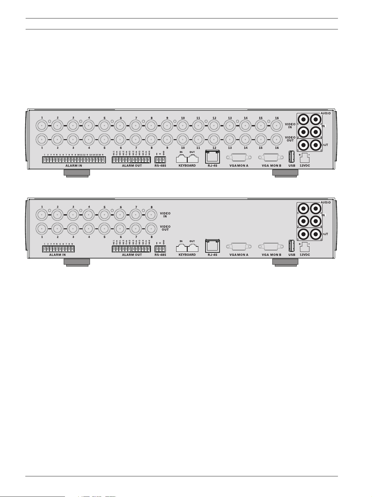
Figure 3.1 Back panel connections for 16-channel model
Figure 3.2 Back panel connections for 8-channel model
3.1.1 Primary connections
1. Connect the cameras to the VIDEO IN BNC connectors (automatically terminated).
2. Connect monitor A to the VGA MON A output supporting 800x600 (4:3), 1024x768 (4:3),
or 1280x1024 (5:4), 1366x768 (16:9) and 1440x900 (16:10).
3. Connect USB mouse to a USB port.
3.1.2 Optional connections
1. Connect monitor B to the VGA MON B connector (supporting 800x600).
2. Connect up to 4 audio signals to the AUDIO IN RCA (CINCH) inputs.
3. Connect 2 AUDIO OUT RCA (CINCH) outputs to the monitor or an audio amplifier.
4. Connect up to 8/16 ALARM IN inputs (via the supplied terminal blocks).
5. Connect up to 4 ALARM OUT outputs (via the supplied terminal blocks).
6. Connect a pan/tilt/zoom control unit to the RS-485 port (via the supplied screw terminal
block).
7. Connect to your network via the Ethernet port.
8. Connect a Bosch Intuikey keyboard cable to the Keyboard-IN port if required.
3.1.3 Powering up
Switch on all connected equipment.
– Connect the power unit to the AC power outlet.
– Connect the DC power cord to the 12VDC connector on the unit.
F.01U.169.663 | v2.0 | 2012.02 Installation and Operation manual Bosch Security Systems
Video Recorder 630/650 Series Quick install | en 17
3.2 First-time use
The Quick install menu opens the first time the unit is used. Fill in the basic settings in the
three tabs to get the unit operational. The unit begins recording automatically when the Quick
install menu is closed.
To open the Quick install menu at any other time:
1. Press the menu key to bring up the System Control Bar.
2. Press the menu key again to enter the main menu.
– The main menu appears on monitor A.
3. Select System, then the Configuration submenu, and finally Quick install.
Navigating
Use the supplied USB mouse. Alternatively, use the following front panel keys:
– Use the enter key to select a submenu or item.
– Use the arrow keys to move through a menu or list.
– Use the exit key to go back or to switch off the menu.
After bootup, the unit presents the log in screen over a quad display. The default User ID is
ADMINISTRATOR, the default password is 000000 (six zeros).
3.2.1 Restoring defaults
To restore the unit to its factory default:
1. Remove power from the DVR.
2. Press and hold the OSD key on the front panel.
3. Supply power to the unit.
– The factory defaults are restored.
Bosch Security Systems Installation and Operation manual F.01U.169.663 | v2.0 | 2012.02
18 en | Quick install Video Recorder 630/650 Series
3.3 Quick install menu
The Quick install menu contains three tabs: International, Continuous Recording, and
Network. Click the Exit button to exit the Quick install menu. Changing Quick install settings
overwrites customized settings.
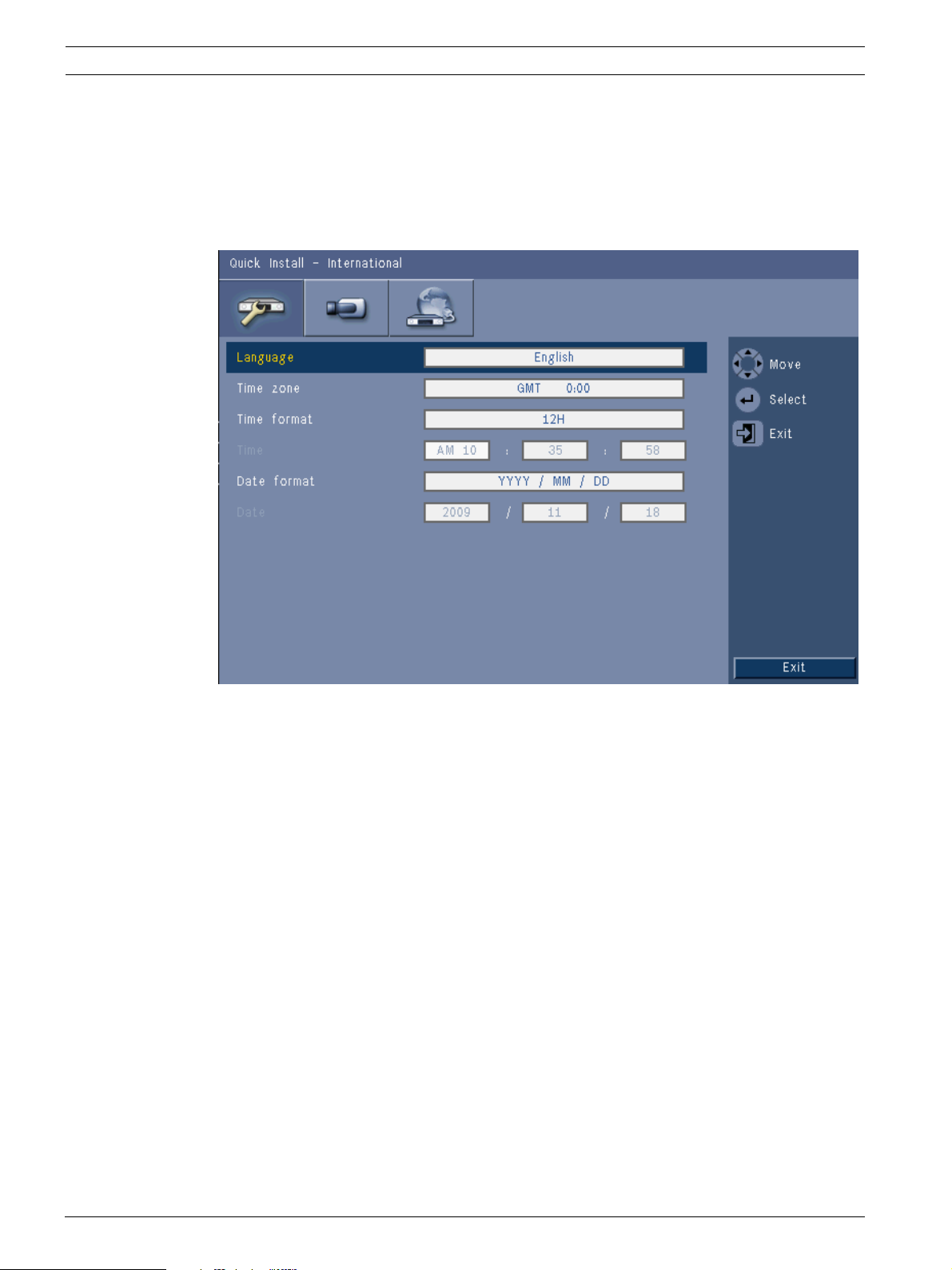
3.3.1 International
Figure 3.3 Quick install - International
Language Select the language for the menu from the list.
Time zone Select a time zone from the list.
Time format Select either a 12 or a 24 hour clock format.
Time Fill in the current time.
Date format Select from three date formats which show either the month (MM),
the day (DD), or the year (YYYY) first.
Date Fill in the current date.
F.01U.169.663 | v2.0 | 2012.02 Installation and Operation manual Bosch Security Systems
Video Recorder 630/650 Series Quick install | en 19
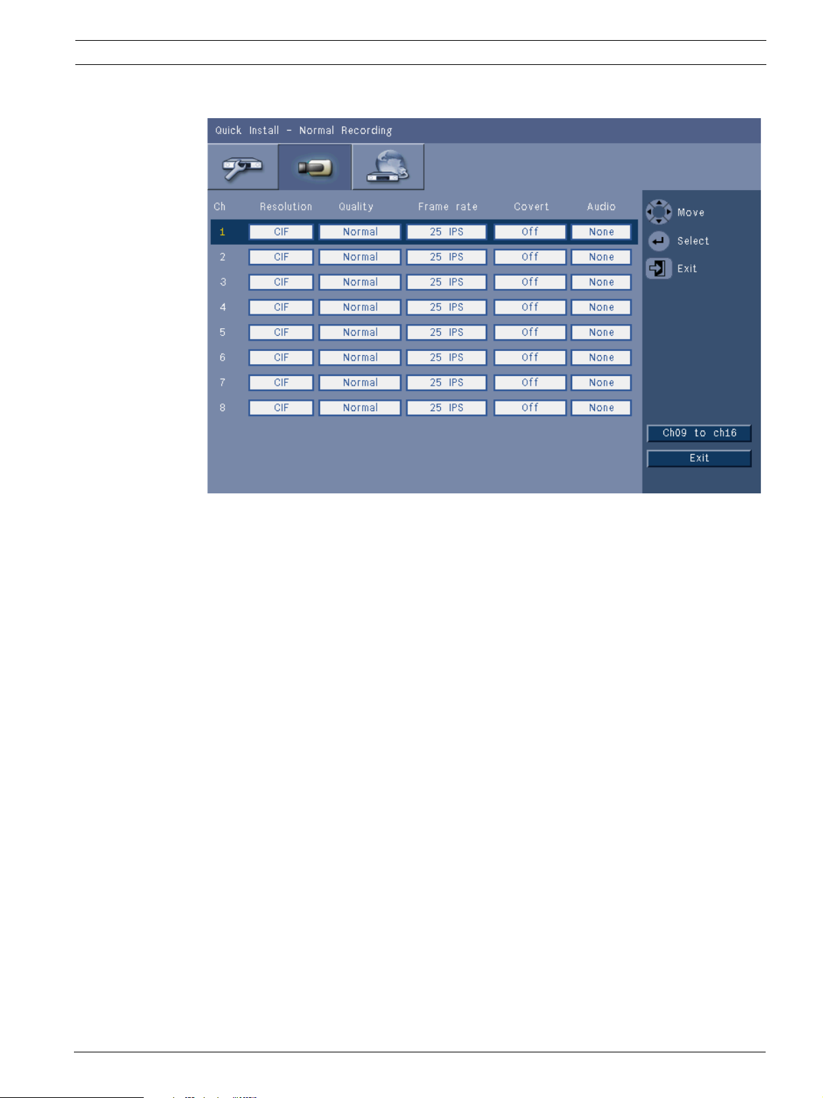
3.3.2 Continuous Recording
Figure 3.4 Quick install - Continuous Recording
Set the Continuous Recording Resolution, Quality, Frame rate, Covert, and Audio for each
profile in the table.
Bosch Security Systems Installation and Operation manual F.01U.169.663 | v2.0 | 2012.02
20 en | Quick install Video Recorder 630/650 Series
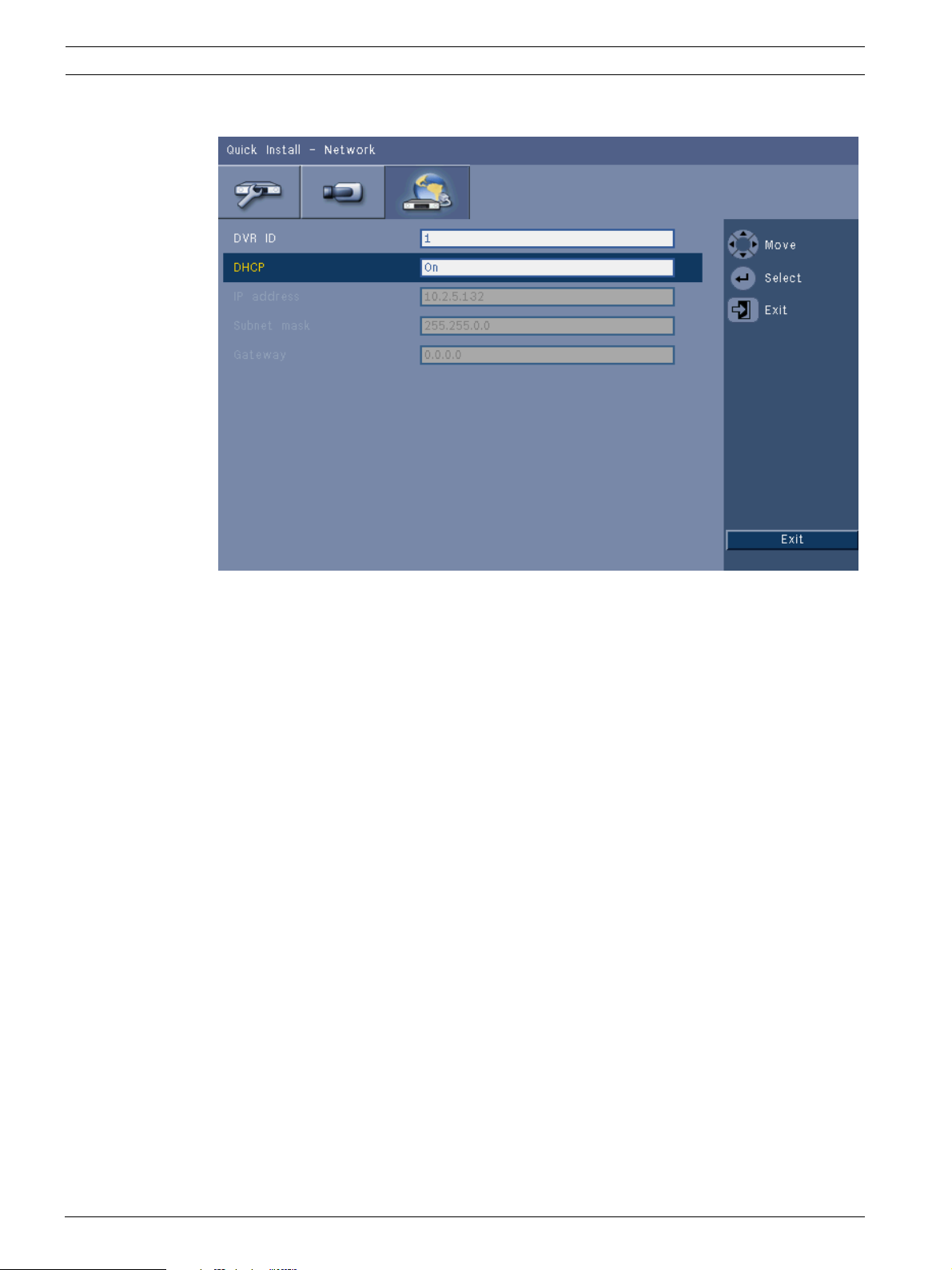
3.3.3 Network
Figure 3.5 Quick install - Network
Fill in the settings that control the behavior of the unit with respect to a network.
DVR ID Enter a unique DVR name to be used in the network.
DHCP Enable DHCP to have IP address, subnet mask, and default
gateway assigned automatically by the network server.
The actual values are displayed.
IP address, Subnet
mask, and Gateway
Fill in the IP, subnet mask, gateway addresses, and DNS server
addresses when DHCP is not enabled.
F.01U.169.663 | v2.0 | 2012.02 Installation and Operation manual Bosch Security Systems
Video Recorder 630/650 Series Hardware setup | en 21
1615141312111098765
1615141312111098765
4 Hardware setup
This chapter contains detailed information about the hardware installation and connection of
external equipment to the unit. The connector types and their pin signals are described. Most
of the connectors are located at the rear panel of the unit. For convenience, one USB port is
located on the front of the unit to connect a mouse or memory device.
All the input/output ports are Safety Extra Low Voltage (SELV) circuits. SELV circuits should
only be connected to other SELV circuits.
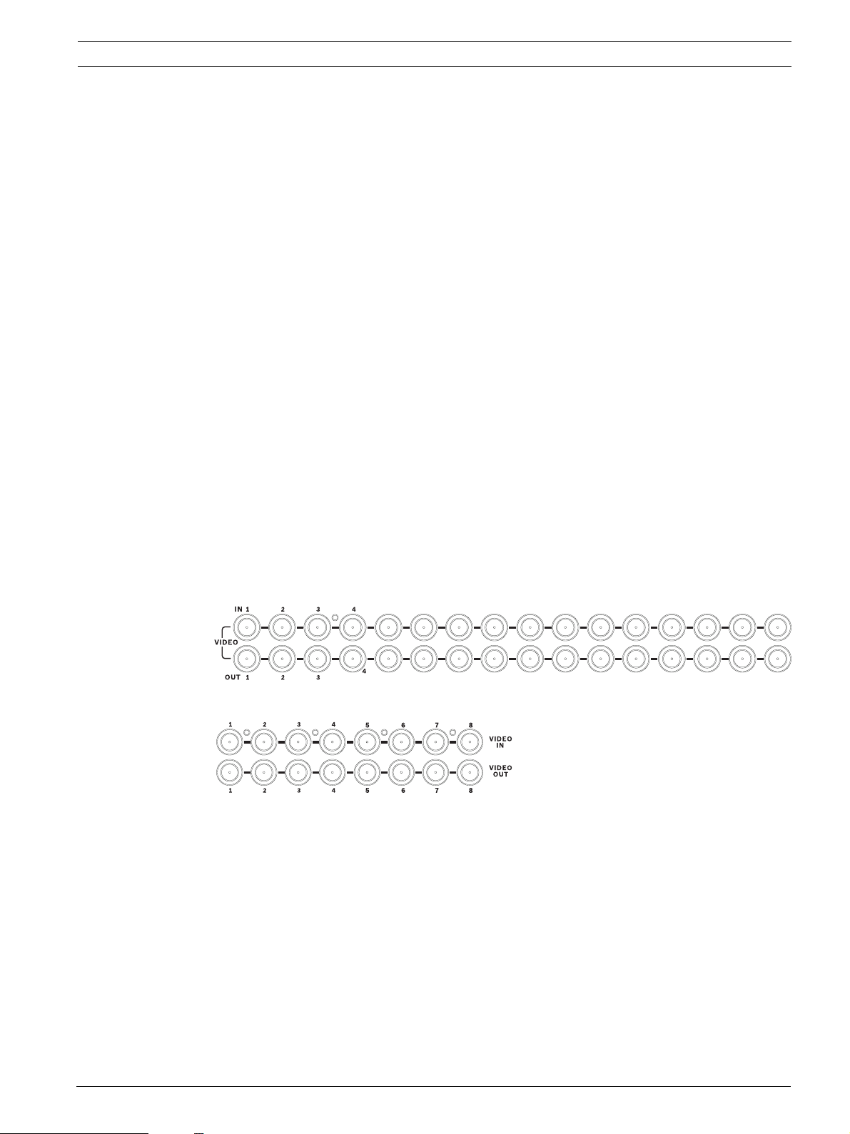
4.1 Camera connections
Connect cameras to the VIDEO IN connectors on the back of the unit using 75 ohm video
coaxial cables with BNC connectors. Optionally, this signal can be looped through to other
equipment via the corresponding VIDEO OUT connector. The camera input connectors are
auto-terminating. There is no need to add a terminator to the output connector if no
additional equipment is connected.
If the camera signal is looped through to additional equipment, make sure that the end of the
video connection is terminated with 75 ohm termination.
The DVR 600 Series automatically configures itself as a PAL or NTSC unit. The unit determines
the TV standard by detecting the signal format of the VIDEO IN 1 during startup. The unit can
also be manually set to PAL or NTSC in the Camera menu under Video format.
Specifications
Input signal: Composite video 1 Vpp, 75 ohm
TV standard: PAL/NTSC, auto-detect
Gain control: Automatic gain control for each video input
Connector type: BNC looped-through, automatic termination
Figure 4.1 16 video inputs with loop-through outputs
Figure 4.2 8 video inputs with loop-through outputs
Bosch Security Systems Installation and Operation manual F.01U.169.663 | v2.0 | 2012.02
22 en | Hardware setup Video Recorder 630/650 Series
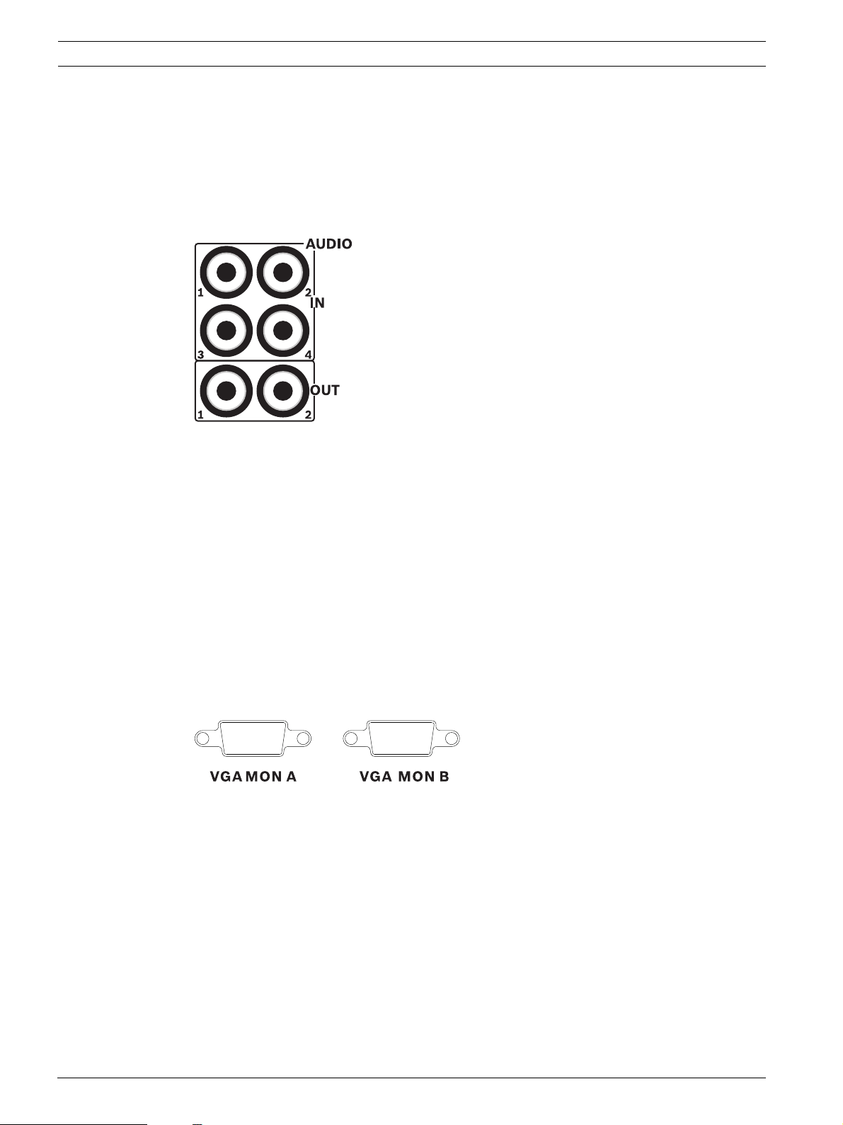
4.2 Audio connections
The DVR 600 Series supports up to 4 audio inputs and 2 audio outputs. Connect using audio
cable with RCA (CINCH) compatible connectors.
Specifications
Input signal: Mono RCA (CINCH), 1 Vpp, 10k ohm
Output signal: Mono RCA (CINCH), 1 Vpp, 10k ohm
Figure 4.3 Audio output and input connectors
4.3 Monitor connections
Up to two monitors can be connected through the VGA connections.
4.3.1 VGA (Monitor A and Monitor B)
Connect the unit to one or two VGA monitors using standard VGA cable. It is advised to use
17” monitors or larger when using LCD(s).
Specifications
Output signal: VGA
Resolution: 800x600 (4:3), 1024x768 (4:3), or 1280x1024 (5:4), 1366x768 (16:9) and
1440x900 (16:10) for Monitor A; 800x600 (4:3) for Monitor B
Color: True color (32 bit)
Connector type: DE-15
Figure 4.4 VGA monitor connectors
F.01U.169.663 | v2.0 | 2012.02 Installation and Operation manual Bosch Security Systems
Video Recorder 630/650 Series Hardware setup | en 23
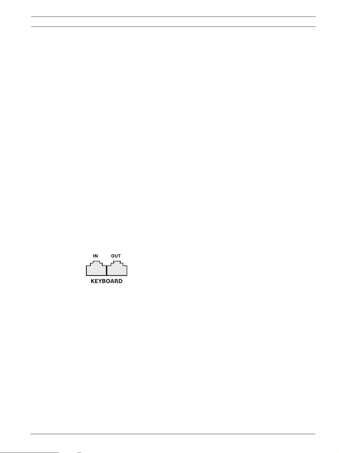
4.4 Keyboard connections
The keyboard input and output connectors are used to connect a Bosch Intuikey keyboard to
one or more DVR 600 Series units.
For one unit, connect the keyboard to the Keyboard in connector. For more units, connect a
cable between the Keyboard out connector of the first unit and the Keyboard in connector of
the following DVR 600 Series unit. Up to 16 DVR 600 Series units can be connected and
controlled in this way with one keyboard.
For short distances (up to 30 m), standard 6-core telecom flat cable can be used to supply
power and signal connections for the keyboard (LTC 8558/00). For distances over 30 m
between the keyboard and the DVR, the Keyboard Extension Kit (LTC 8557) must be used.
This kit provides junction boxes, cables, and the appropriate power supply for the external
keyboard. The recommended cable type is Belden 8760 or equivalent.
Termination
Connect the keyboard terminator (supplied with the Intuikey keyboard) to the Keyboard out
connector of the last DVR in the circuit. If multiple DVR 600 Series units are controlled with a
single keyboard, the Keyboard out connector of the last DVR 600 Series unit must be
terminated.
Specifications
– Communicaton protocol: RS485
– Maximum signal voltage: ± 12 V
– Power supply: 11 - 12.6 VDC, maximum 400 mA
– Maximum cable length: 30 m (using standard 6-core telecom flat cable), or 1.5 km (using
Belden 8760 or equivalent in combination with the LTC 8557).
– Cable type: black (cross-over) cable (supplied with keyboard)
– Termination: 390 Ohm terminator
– Connector: RJ11 (6-pin)
Figure 4.5 Keyboard input and output connectors
Bosch Security Systems Installation and Operation manual F.01U.169.663 | v2.0 | 2012.02

24 en | Hardware setup Video Recorder 630/650 Series
4.5 Ethernet connection
The standard RJ-45 Ethernet socket is used to connect the unit directly to a PC or to a
network. To connect directly to a network hub or switch, use a straight-through network
cable. To connect directly to a PC, use a cross-over network cable. Consult with your local IT
personnel for the specific type of cable needed. The maximum cable length from node to node
is limited to 100 meters (300 feet).
Specifications
– 1000 Base-T IEEE 802.3ab compliant, 100Base-TX IEEE 802.3u Compliant, 10Base-T IEEE
802.3 Compliant
– IEEE 802.3 Compliant RGMII/MII
– DSP processing
– Transmission rate up to 1Gbps over industry standard CAT.5 UTP cable with BER less
than 10
– Supports 3.3V or 2.5V signaling for RGMII
– Supports power down mode and supports Link Down Power Saving
– 64-pin QFN or 100-pin LQFP
– Connector: RJ45
-10
in 1000Base-T
Figure 4.6 RJ-45 Ethernet connector
F.01U.169.663 | v2.0 | 2012.02 Installation and Operation manual Bosch Security Systems
Video Recorder 630/650 Series Hardware setup | en 25
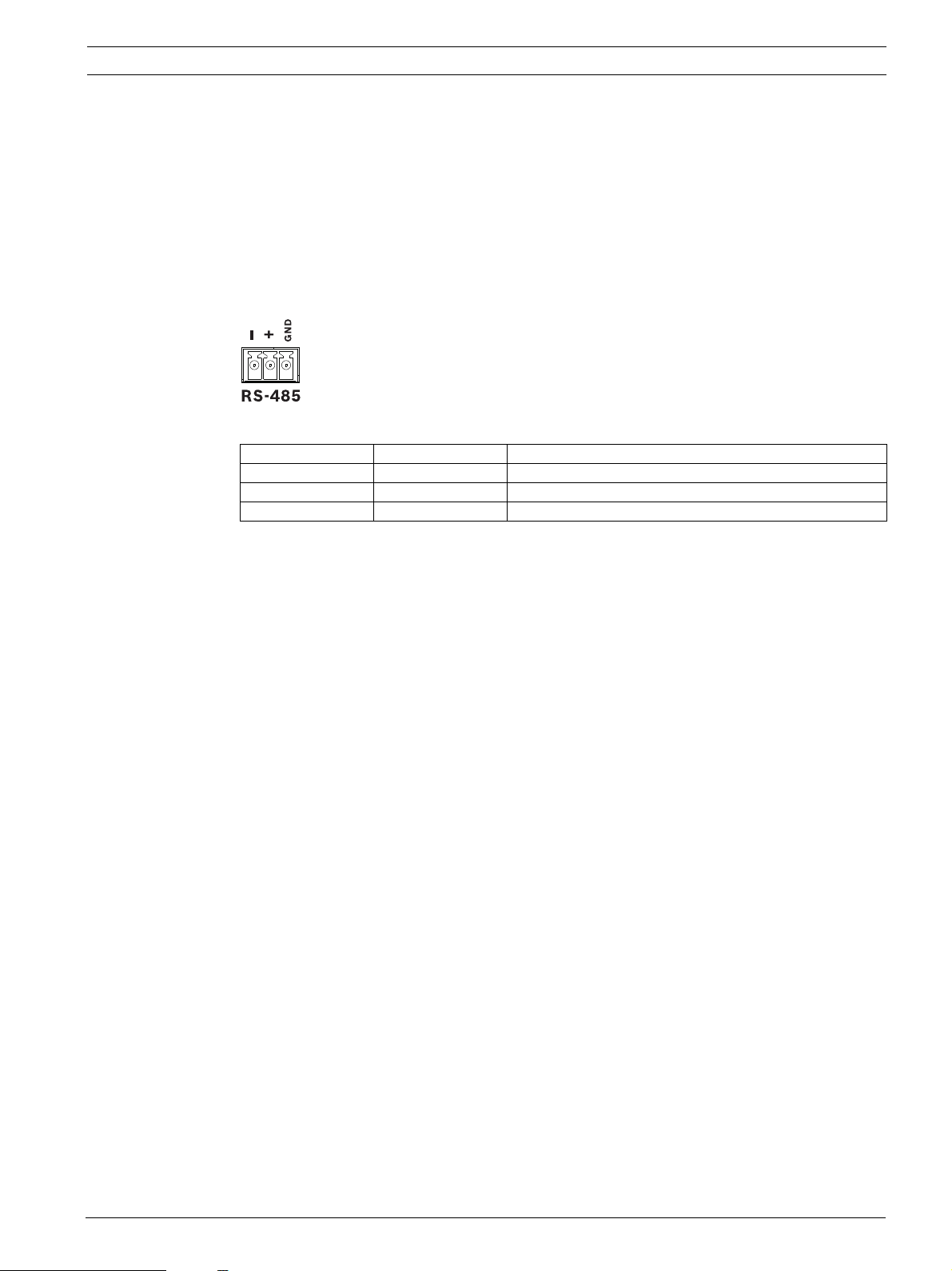
4.6 RS485 port
Connect Bosch, Pelco-P or Pelco-D controllable cameras to the unit for pan, tilt, and zoom
control.
The Bosch protocol is supported with the following baud settings:
– 9600 baud
– 8 data bits
–1 stop bit
– no parity
– no flow control
Figure 4.7 RS-485 connector
Signal name Pin number Description
TX - 1 Data transmission
TX + 2 Data transmission
GND 3 Shield
Tab le 4.1 RS485 pin definition
The recommended cable cross section is AWG 28-16 (0.08-1.5 mm2).
Bosch Security Systems Installation and Operation manual F.01U.169.663 | v2.0 | 2012.02

26 en | Hardware setup Video Recorder 630/650 Series
4.7 USB connectors
A USB 2.0 connector is located at the rear panel of the unit to which a mouse, for example,
can be connected. For convenience, the USB 2.0 port is located on the front of the unit to
connect a mouse or USB memory device. (Recording to a USB-drive is not supported.)
Figure 4.8 USB connector (on front and on rear)
Note:
USB memory sticks must have FAT32 formatting.
F.01U.169.663 | v2.0 | 2012.02 Installation and Operation manual Bosch Security Systems
Video Recorder 630/650 Series Hardware setup | en 27
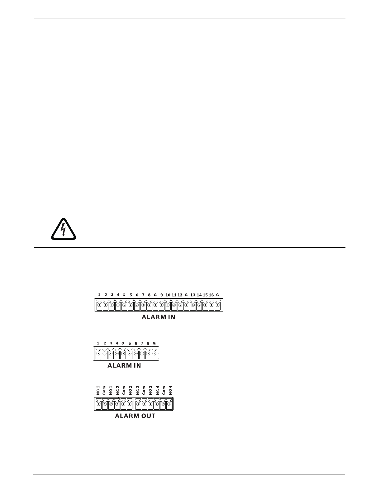
4.8 External alarm I/O connection
Alarm inputs and outputs are supplied screw down terminal blocks. The screw terminal blocks
are supplied with the unit.
Connecting the inputs
Each (alarm) input line can be switched by a contact from an external device between an
numbered input and ground (G). Wire them as either Normally Open (N/O) or Normally
Closed (N/C). Configure the alarm inputs as N/O or N/C in the menu system. The default is N/
O.
Specifications
Alarm input impedence: Internal pull-up 10 kOhm to +5 V
Input voltage range: -2 VDC minimum to 15 VDC maximum
Input voltage threshold: low voltage 0.5 V maximum, high voltage 2 V minimum
Cable cross section: AWG 26-16 (0.13-1.5 mm2)
Connecting the alarm outputs
The four alarm output relays respond to input alarms and triggers. Configure the alarm
outputs as N/O or N/C in the menu system. Only connect resistive loads to the alarm output
relays. Do not exceed 30 Vac, 40 Vdc, 500 mA (continuous), or 10 VA on an alarm output
relay's contacts.
DANGER!
Electrical voltage.
Risk of electric shock and damage to the unit.
The contacts must not be used at AC line voltages.
Specifications
Switching current (resistive): 500 mA maximum
Switching voltage (resistive): 30 VAC/40 VDC maximum
Cable cross section: AWG 26-16 (0.13-1.5 mm2)
Figure 4.9 Alarm input connector for 16-channel model
Figure 4.10 Alarm input connector for 8-channel model
Figure 4.11 Alarm output connector
Bosch Security Systems Installation and Operation manual F.01U.169.663 | v2.0 | 2012.02
28 en | Hardware setup Video Recorder 630/650 Series
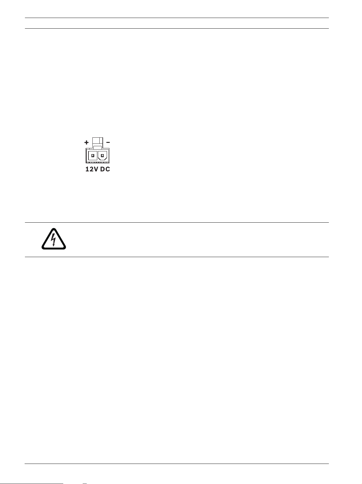
4.9 Power supply
DC power is supplied to the DVR 600 from an AC/DC power supply unit delivered with the
unit. For operational reasons, the DVR 600 has no on/off switch . This means that the unit is
always powered as long as the power cable from the power supply unit is connected to the
12VDC socket.
Specifications:
– External power supply unit:
– AC input: 100-240 VAC; 1.8 A; 50/60 Hz
– DC output: 12 VDC; 5 A
– DVR power input: 12 VDC; 3.5 A
Figure 4.12 12 VDC power supply socket
4.10 Maintenance
Maintenance of this unit is limited to external cleaning and inspection. Refer all servicing to
qualified service personnel.
DANGER!
Electrical voltage. Risk of electric shock.
Do not open the top cover or attempt to service the unit. No user serviceable parts inside.
Refer all servicing to qualified service personnel.
F.01U.169.663 | v2.0 | 2012.02 Installation and Operation manual Bosch Security Systems
Video Recorder 630/650 Series Operating instructions | en 29
5 Operating instructions
These instructions explain the purpose of the front panel keys. The functions available can be
limited by setting passwords.
Access to the units functions are determined by the user level of the user logged in.
Function Administrator level Advanced User level Normal User level
View live Yes Yes Yes
Sequence Yes Yes Yes
Quad Yes Yes Yes
OSD Yes Yes Yes
Zoom Yes Yes Yes
Pan/Tilt/Zoom (PTZ) Yes Yes Yes
Playback Yes Yes No (configurable)
Search Yes Yes No (configurable)
Export Yes Yes No (configurable)
Acknowledge Alarm Yes Yes No (configurable)
System Menus Yes No No
Covert Yes No No
Tab le 5.1 User Levels and permissions
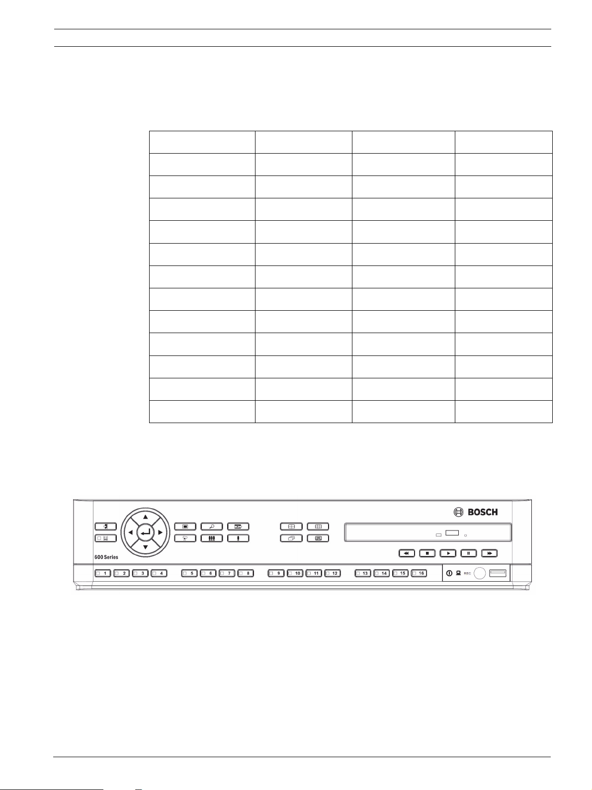
5.1 Front panel controls
Figure 5.1 Front panel controls
Note:
8-channel models have only 8 camera keys on the front.
Bosch Security Systems Installation and Operation manual F.01U.169.663 | v2.0 | 2012.02
30 en | Operating instructions Video Recorder 630/650 Series
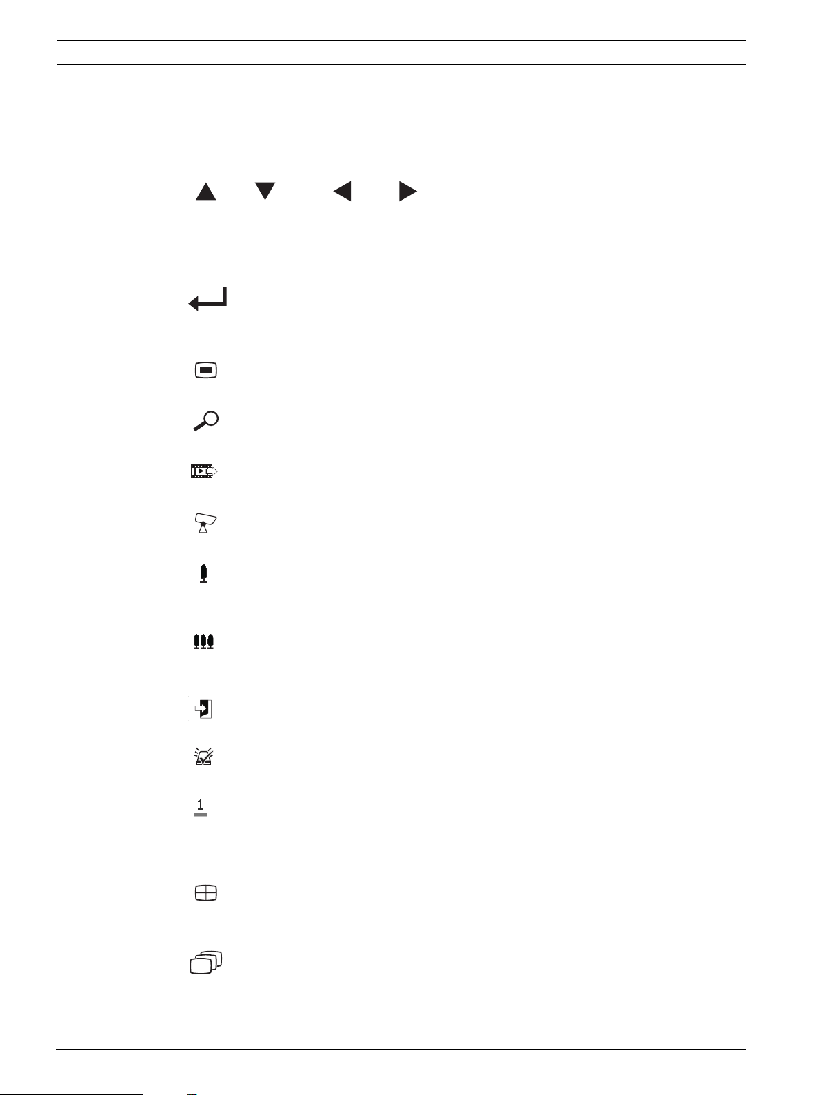
5.1.1 Keys
The keys on the front panel control all functions. Symbols on the keys show the functions.
Inactive keys emit an audible beep when pressed.
Arrow keys:
Up, Down, Left, Right
– move around through menu items or values when in menu mode
– in PTZ mode, the arrow keys can be used to control the pan or tilt functions of the
selected camera
– moves the visible area of the selected image in digital zoom mode
Enter key
– selects a submenu or menu item, or confirms selections made in menus
– brings up the cameo submenu in full screen or quad modes
Menu key
– opens the system menu
Search key
– press to open the date/time search menu to look for recorded images
Export key
– press to open the export menu
PTZ key
– enables or disables the PTZ mode
Zoom in key
– PTZ zoom in key
– Digital zoom in key on active full-screen display
Zoom out key
– PTZ zoom out key
– Digital zoom out key
Exit key
– press to return to previous level or to exit the menu system
Acknowledge key
– press to acknowledge an alarm event; a red indicator light is located on the key
Camera keys (1-8/16)
– press to see a full-screen display of the video input
– the LED will be illuminated when the camera is recording
– the LED will flash during an alarm on the camera
Quad key
– press to go to quad mode
– in quad mode, press to toggle to full screen
Sequence key
– view cameras in sequence on full-screen or quad displays
F.01U.169.663 | v2.0 | 2012.02 Installation and Operation manual Bosch Security Systems
Loading...