


 Loading...
RAID Subsystem DVA-08K
DVA-08K SCSI Premium Series
en Installation Manual

RAID Subsystem DVA-08K | Installation Manual |
Table of Contents | en |
3 |
|
Table of Contents |
|
|
|
1 |
Warnings and Certifications . . . . . . . . . . . . . . . . . . . . . . . . . . . . . . . . . . . . . . . . . |
. . . . . . . . . . . . . . . . |
. 5 |
1.1 |
Warning . . . . . . . . . . . . . . . . . . . . . . . . . . . . . . . . . . . . . . . . . . . . . . . . . . . . . . . . . |
. . . . . . . . . . . . . . . . . |
5 |
1.2 |
Safety Precautions . . . . . . . . . . . . . . . . . . . . . . . . . . . . . . . . . . . . . . . . . . . . . . . . |
. . . . . . . . . . . . . . . . . |
5 |
1.3 |
Certification . . . . . . . . . . . . . . . . . . . . . . . . . . . . . . . . . . . . . . . . . . . . . . . . . . . . . |
. . . . . . . . . . . . . . . . . |
5 |
2 |
Introduction. . . . . . . . . . . . . . . . . . . . . . . . . . . . . . . . . . . . . . . . . . . . . . . . . . . . . . |
. . . . . . . . . . . . . . . . . |
7 |
2.1 |
Product Overview . . . . . . . . . . . . . . . . . . . . . . . . . . . . . . . . . . . . . . . . . . . . . . . . . |
. . . . . . . . . . . . . . . . . |
7 |
2.2 |
Enclosure Chassis . . . . . . . . . . . . . . . . . . . . . . . . . . . . . . . . . . . . . . . . . . . . . . . . . |
. . . . . . . . . . . . . . . . . |
9 |
2.2.1 |
Chassis Overview . . . . . . . . . . . . . . . . . . . . . . . . . . . . . . . . . . . . . . . . . . . . . . . . . |
. . . . . . . . . . . . . . . . . |
9 |
2.2.2 |
Physical Dimensions . . . . . . . . . . . . . . . . . . . . . . . . . . . . . . . . . . . . . . . . . . . . . . . |
. . . . . . . . . . . . . . . . . |
9 |
2.2.3 |
Front Panel Overview . . . . . . . . . . . . . . . . . . . . . . . . . . . . . . . . . . . . . . . . . . . . . . |
. . . . . . . . . . . . . . . . . |
9 |
2.2.4 |
Hard Drive Numbering . . . . . . . . . . . . . . . . . . . . . . . . . . . . . . . . . . . . . . . . . . . . . . |
. . . . . . . . . . . . . . . . |
10 |
2.2.5 |
Rear Panel Overview . . . . . . . . . . . . . . . . . . . . . . . . . . . . . . . . . . . . . . . . . . . . . . . |
. . . . . . . . . . . . . . . . |
10 |
2.2.6 |
Backplane Board . . . . . . . . . . . . . . . . . . . . . . . . . . . . . . . . . . . . . . . . . . . . . . . . . . |
. . . . . . . . . . . . . . . . |
11 |
2.3 |
Subsystem Components . . . . . . . . . . . . . . . . . . . . . . . . . . . . . . . . . . . . . . . . . . . . |
. . . . . . . . . . . . . . . . |
12 |
2.3.1 |
LCD Panel . . . . . . . . . . . . . . . . . . . . . . . . . . . . . . . . . . . . . . . . . . . . . . . . . . . . . . . |
. . . . . . . . . . . . . . . . |
12 |
2.3.2 |
Drive Trays. . . . . . . . . . . . . . . . . . . . . . . . . . . . . . . . . . . . . . . . . . . . . . . . . . . . . . . |
. . . . . . . . . . . . . . . . |
13 |
2.3.3 |
The RAID Controller Module . . . . . . . . . . . . . . . . . . . . . . . . . . . . . . . . . . . . . . . . . |
. . . . . . . . . . . . . . . . |
13 |
2.3.4 |
Battery Backup Unit . . . . . . . . . . . . . . . . . . . . . . . . . . . . . . . . . . . . . . . . . . . . . . . |
. . . . . . . . . . . . . . . . |
14 |
2.3.5 |
Power Supply Units . . . . . . . . . . . . . . . . . . . . . . . . . . . . . . . . . . . . . . . . . . . . . . . . |
. . . . . . . . . . . . . . . . |
15 |
2.3.6 |
Cooling Fan Modules . . . . . . . . . . . . . . . . . . . . . . . . . . . . . . . . . . . . . . . . . . . . . . . |
. . . . . . . . . . . . . . . . |
15 |
2.4 |
Subsystem Monitoring. . . . . . . . . . . . . . . . . . . . . . . . . . . . . . . . . . . . . . . . . . . . . . |
. . . . . . . . . . . . . . . . |
17 |
2.4.1 |
I2C Bus . . . . . . . . . . . . . . . . . . . . . . . . . . . . . . . . . . . . . . . . . . . . . . . . . . . . . . . . . |
. . . . . . . . . . . . . . . . |
17 |
2.4.2 |
LED Indicators . . . . . . . . . . . . . . . . . . . . . . . . . . . . . . . . . . . . . . . . . . . . . . . . . . . . |
. . . . . . . . . . . . . . . . |
17 |
2.4.3 |
Firmware and Bosch RAIDWatch GUI . . . . . . . . . . . . . . . . . . . . . . . . . . . . . . . . . . |
. . . . . . . . . . . . . . . . |
17 |
2.4.4 |
Audible Alarms . . . . . . . . . . . . . . . . . . . . . . . . . . . . . . . . . . . . . . . . . . . . . . . . . . . |
. . . . . . . . . . . . . . . . |
17 |
2.5 |
Hot-Swappable Components. . . . . . . . . . . . . . . . . . . . . . . . . . . . . . . . . . . . . . . . . |
. . . . . . . . . . . . . . . . |
18 |
2.5.1 |
Hot-Swap Capabilities . . . . . . . . . . . . . . . . . . . . . . . . . . . . . . . . . . . . . . . . . . . . . . |
. . . . . . . . . . . . . . . . |
18 |
2.5.2 |
Components . . . . . . . . . . . . . . . . . . . . . . . . . . . . . . . . . . . . . . . . . . . . . . . . . . . . . |
. . . . . . . . . . . . . . . . |
18 |
2.5.3 |
Normalized Airflow . . . . . . . . . . . . . . . . . . . . . . . . . . . . . . . . . . . . . . . . . . . . . . . . |
. . . . . . . . . . . . . . . . |
18 |
3 |
Hardware Installation . . . . . . . . . . . . . . . . . . . . . . . . . . . . . . . . . . . . . . . . . . . . . . |
. . . . . . . . . . . . . . . . |
19 |
3.1 |
Installation Prerequisites . . . . . . . . . . . . . . . . . . . . . . . . . . . . . . . . . . . . . . . . . . . |
. . . . . . . . . . . . . . . . |
19 |
3.2 |
Safety Precautions . . . . . . . . . . . . . . . . . . . . . . . . . . . . . . . . . . . . . . . . . . . . . . . . |
. . . . . . . . . . . . . . . . |
20 |
3.2.1 |
Precautions and Instructions . . . . . . . . . . . . . . . . . . . . . . . . . . . . . . . . . . . . . . . . |
. . . . . . . . . . . . . . . . |
20 |
3.2.2 |
Static-Free Installation . . . . . . . . . . . . . . . . . . . . . . . . . . . . . . . . . . . . . . . . . . . . . |
. . . . . . . . . . . . . . . . |
20 |
3.2.3 |
BBU Warnings and Precautions. . . . . . . . . . . . . . . . . . . . . . . . . . . . . . . . . . . . . . . |
. . . . . . . . . . . . . . . . |
20 |
3.3 |
General Installation Procedure . . . . . . . . . . . . . . . . . . . . . . . . . . . . . . . . . . . . . . . |
. . . . . . . . . . . . . . . . |
22 |
3.3.1 |
Installation Procedure Flowchart . . . . . . . . . . . . . . . . . . . . . . . . . . . . . . . . . . . . . |
. . . . . . . . . . . . . . . . |
22 |
3.4 |
Unpacking the Subsystem . . . . . . . . . . . . . . . . . . . . . . . . . . . . . . . . . . . . . . . . . . . |
. . . . . . . . . . . . . . . . |
22 |
3.5 |
Rackmounting . . . . . . . . . . . . . . . . . . . . . . . . . . . . . . . . . . . . . . . . . . . . . . . . . . . . |
. . . . . . . . . . . . . . . . |
23 |
3.5.1 |
Considerations for Installation Site and Chassis . . . . . . . . . . . . . . . . . . . . . . . . . |
. . . . . . . . . . . . . . . . |
23 |
3.5.2 |
Mounting Holes Positions . . . . . . . . . . . . . . . . . . . . . . . . . . . . . . . . . . . . . . . . . . . |
. . . . . . . . . . . . . . . . |
23 |
3.6 |
Drive Tray Installation . . . . . . . . . . . . . . . . . . . . . . . . . . . . . . . . . . . . . . . . . . . . . . |
. . . . . . . . . . . . . . . . |
24 |
4 |
Subsystem Monitoring. . . . . . . . . . . . . . . . . . . . . . . . . . . . . . . . . . . . . . . . . . . . . . |
. . . . . . . . . . . . . . . . |
26 |
4.1 |
Subsystem Monitoring Overview. . . . . . . . . . . . . . . . . . . . . . . . . . . . . . . . . . . . . . |
. . . . . . . . . . . . . . . . |
26 |
4.2 |
Status-indicating LEDs . . . . . . . . . . . . . . . . . . . . . . . . . . . . . . . . . . . . . . . . . . . . . |
. . . . . . . . . . . . . . . . |
27 |
4.2.1 |
Brief Overview of the LEDs . . . . . . . . . . . . . . . . . . . . . . . . . . . . . . . . . . . . . . . . . . |
. . . . . . . . . . . . . . . . |
27 |
4.2.2 |
Drive Tray LEDs . . . . . . . . . . . . . . . . . . . . . . . . . . . . . . . . . . . . . . . . . . . . . . . . . . . |
. . . . . . . . . . . . . . . . |
28 |
4.2.3 |
Controller Module LEDs . . . . . . . . . . . . . . . . . . . . . . . . . . . . . . . . . . . . . . . . . . . . |
. . . . . . . . . . . . . . . . |
28 |
4.2.4 |
Ethernet Port LEDs . . . . . . . . . . . . . . . . . . . . . . . . . . . . . . . . . . . . . . . . . . . . . . . . |
. . . . . . . . . . . . . . . . |
29 |
4.2.5 |
BBU Module LED . . . . . . . . . . . . . . . . . . . . . . . . . . . . . . . . . . . . . . . . . . . . . . . . . . |
. . . . . . . . . . . . . . . . |
30 |
4.2.6 |
PSU LED . . . . . . . . . . . . . . . . . . . . . . . . . . . . . . . . . . . . . . . . . . . . . . . . . . . . . . . . |
. . . . . . . . . . . . . . . . |
30 |
4.2.7 |
LCD Keypad Panel . . . . . . . . . . . . . . . . . . . . . . . . . . . . . . . . . . . . . . . . . . . . . . . . . |
. . . . . . . . . . . . . . . . |
30 |
4.2.8 |
Cooling Fan Module LED . . . . . . . . . . . . . . . . . . . . . . . . . . . . . . . . . . . . . . . . . . . . |
. . . . . . . . . . . . . . . . |
31 |
4.3 |
Audible Alarm . . . . . . . . . . . . . . . . . . . . . . . . . . . . . . . . . . . . . . . . . . . . . . . . . . . . |
. . . . . . . . . . . . . . . . |
32 |
4.3.1 |
Default Threshold Values. . . . . . . . . . . . . . . . . . . . . . . . . . . . . . . . . . . . . . . . . . . . |
. . . . . . . . . . . . . . . . |
32 |
4.3.2 |
Failed Devices . . . . . . . . . . . . . . . . . . . . . . . . . . . . . . . . . . . . . . . . . . . . . . . . . . . . |
. . . . . . . . . . . . . . . . |
33 |
4.4 |
I2C Monitoring . . . . . . . . . . . . . . . . . . . . . . . . . . . . . . . . . . . . . . . . . . . . . . . . . . . . |
. . . . . . . . . . . . . . . . |
33 |
Bosch Security Systems |
F.01U.027.797 | V2 | 2008.08 |

4 en | Table of Contents |
RAID Subsystem DVA-08K | Installation Manual |
|
5 |
Subsystem Connection and Operation. . . . . . . . . . . . . . . . . . . . |
. . . . . . . . . . . . . . . . . . . . . . . . . . . . . . 34 |
5.1 |
Basic Configuration Rules . . . . . . . . . . . . . . . . . . . . . . . . . . . . . . |
. . . . . . . . . . . . . . . . . . . . . . . . . . . . . 34 |
5.2 |
SCSI Connection Overview . . . . . . . . . . . . . . . . . . . . . . . . . . . . . |
. . . . . . . . . . . . . . . . . . . . . . . . . . . . . 35 |
5.2.1 |
SCSI Cables . . . . . . . . . . . . . . . . . . . . . . . . . . . . . . . . . . . . . . . . . |
. . . . . . . . . . . . . . . . . . . . . . . . . . . . . 35 |
5.2.2 |
SCSI Port on the Controller Rear Panel . . . . . . . . . . . . . . . . . . . . |
. . . . . . . . . . . . . . . . . . . . . . . . . . . . . 35 |
5.2.3 |
SCSI Termination . . . . . . . . . . . . . . . . . . . . . . . . . . . . . . . . . . . . . |
. . . . . . . . . . . . . . . . . . . . . . . . . . . . . 36 |
5.3 |
Host Connection Topology . . . . . . . . . . . . . . . . . . . . . . . . . . . . . . |
. . . . . . . . . . . . . . . . . . . . . . . . . . . . . 37 |
5.4 |
Power On . . . . . . . . . . . . . . . . . . . . . . . . . . . . . . . . . . . . . . . . . . . |
. . . . . . . . . . . . . . . . . . . . . . . . . . . . . 38 |
5.4.1 |
Power On Checklist . . . . . . . . . . . . . . . . . . . . . . . . . . . . . . . . . . . |
. . . . . . . . . . . . . . . . . . . . . . . . . . . . . 38 |
5.4.2 |
Power On Sequence. . . . . . . . . . . . . . . . . . . . . . . . . . . . . . . . . . . |
. . . . . . . . . . . . . . . . . . . . . . . . . . . . . 38 |
5.4.3 |
Power On Procedure . . . . . . . . . . . . . . . . . . . . . . . . . . . . . . . . . . |
. . . . . . . . . . . . . . . . . . . . . . . . . . . . . 38 |
5.4.4 |
Power On Status Check . . . . . . . . . . . . . . . . . . . . . . . . . . . . . . . . |
. . . . . . . . . . . . . . . . . . . . . . . . . . . . . 39 |
5.4.5 |
LCD Screen . . . . . . . . . . . . . . . . . . . . . . . . . . . . . . . . . . . . . . . . . |
. . . . . . . . . . . . . . . . . . . . . . . . . . . . . 39 |
5.5 |
Power Off Procedure . . . . . . . . . . . . . . . . . . . . . . . . . . . . . . . . . . |
. . . . . . . . . . . . . . . . . . . . . . . . . . . . . 41 |
6 |
Subsystem Maintenance . . . . . . . . . . . . . . . . . . . . . . . . . . . . . . . |
. . . . . . . . . . . . . . . . . . . . . . . . . . . . . 42 |
6.1 |
Overview. . . . . . . . . . . . . . . . . . . . . . . . . . . . . . . . . . . . . . . . . . . . |
. . . . . . . . . . . . . . . . . . . . . . . . . . . . . 42 |
6.1.1 |
General Notes on Component Replacement . . . . . . . . . . . . . . . . |
. . . . . . . . . . . . . . . . . . . . . . . . . . . . . 42 |
6.2 |
Replacing Controller Module Components . . . . . . . . . . . . . . . . . |
. . . . . . . . . . . . . . . . . . . . . . . . . . . . . 43 |
6.2.1 |
Overview. . . . . . . . . . . . . . . . . . . . . . . . . . . . . . . . . . . . . . . . . . . . |
. . . . . . . . . . . . . . . . . . . . . . . . . . . . . 43 |
6.2.2 |
Notes on Controller Module Maintenance . . . . . . . . . . . . . . . . . . |
. . . . . . . . . . . . . . . . . . . . . . . . . . . . . 43 |
6.2.3 |
Removing the Controller Module . . . . . . . . . . . . . . . . . . . . . . . . . |
. . . . . . . . . . . . . . . . . . . . . . . . . . . . . 43 |
6.2.4 |
Replacing the Controller Module . . . . . . . . . . . . . . . . . . . . . . . . . |
. . . . . . . . . . . . . . . . . . . . . . . . . . . . . 44 |
6.3 |
Replacing or Upgrading Memory Modules . . . . . . . . . . . . . . . . . . |
. . . . . . . . . . . . . . . . . . . . . . . . . . . . . 45 |
6.3.1 |
Memory Module Installation Overview . . . . . . . . . . . . . . . . . . . . . |
. . . . . . . . . . . . . . . . . . . . . . . . . . . . . 45 |
6.3.2 |
Selecting a Memory Module . . . . . . . . . . . . . . . . . . . . . . . . . . . . . |
. . . . . . . . . . . . . . . . . . . . . . . . . . . . . 45 |
6.3.3 |
DIMM Module Installation . . . . . . . . . . . . . . . . . . . . . . . . . . . . . . |
. . . . . . . . . . . . . . . . . . . . . . . . . . . . . 45 |
6.4 |
Replacing a Faulty BBU . . . . . . . . . . . . . . . . . . . . . . . . . . . . . . . . |
. . . . . . . . . . . . . . . . . . . . . . . . . . . . . 47 |
6.5 |
Replacing a Failed PSU Module . . . . . . . . . . . . . . . . . . . . . . . . . . |
. . . . . . . . . . . . . . . . . . . . . . . . . . . . . 47 |
6.5.1 |
Notes on PSU Module Maintenance . . . . . . . . . . . . . . . . . . . . . . . |
. . . . . . . . . . . . . . . . . . . . . . . . . . . . . 47 |
6.5.2 |
Replacing the PSU Module . . . . . . . . . . . . . . . . . . . . . . . . . . . . . . |
. . . . . . . . . . . . . . . . . . . . . . . . . . . . . 47 |
6.6 |
Replacing a Failed Cooling Fan Module . . . . . . . . . . . . . . . . . . . . |
. . . . . . . . . . . . . . . . . . . . . . . . . . . . . 50 |
6.6.1 |
Notes on Cooling Fan Module Maintenance . . . . . . . . . . . . . . . . . |
. . . . . . . . . . . . . . . . . . . . . . . . . . . . . 50 |
6.6.2 |
Replacing a Cooling Fan Module . . . . . . . . . . . . . . . . . . . . . . . . . |
. . . . . . . . . . . . . . . . . . . . . . . . . . . . . 50 |
6.7 |
Drive Tray Maintenance . . . . . . . . . . . . . . . . . . . . . . . . . . . . . . . . |
. . . . . . . . . . . . . . . . . . . . . . . . . . . . . 51 |
6.7.1 |
Notes on Hard Drive Maintenance . . . . . . . . . . . . . . . . . . . . . . . . |
. . . . . . . . . . . . . . . . . . . . . . . . . . . . . 51 |
6.7.2 |
Replacing a Failed Hard Drive . . . . . . . . . . . . . . . . . . . . . . . . . . . |
. . . . . . . . . . . . . . . . . . . . . . . . . . . . . 51 |
7 |
Appendix: Technical Specifications . . . . . . . . . . . . . . . . . . . . . . . |
. . . . . . . . . . . . . . . . . . . . . . . . . . . . . 54 |
7.1 |
Controller Specifications . . . . . . . . . . . . . . . . . . . . . . . . . . . . . . . |
. . . . . . . . . . . . . . . . . . . . . . . . . . . . . 56 |
7.1.1 |
Configuration . . . . . . . . . . . . . . . . . . . . . . . . . . . . . . . . . . . . . . . . |
. . . . . . . . . . . . . . . . . . . . . . . . . . . . . 56 |
7.1.2 |
Architecture . . . . . . . . . . . . . . . . . . . . . . . . . . . . . . . . . . . . . . . . . |
. . . . . . . . . . . . . . . . . . . . . . . . . . . . . 56 |
7.2 |
Drive Tray Specifications . . . . . . . . . . . . . . . . . . . . . . . . . . . . . . . |
. . . . . . . . . . . . . . . . . . . . . . . . . . . . . 57 |
7.3 |
Power Supply Specifications . . . . . . . . . . . . . . . . . . . . . . . . . . . . |
. . . . . . . . . . . . . . . . . . . . . . . . . . . . . 57 |
7.4 |
Cooling Module Specifications. . . . . . . . . . . . . . . . . . . . . . . . . . . |
. . . . . . . . . . . . . . . . . . . . . . . . . . . . . 58 |
7.5 |
RAID Management . . . . . . . . . . . . . . . . . . . . . . . . . . . . . . . . . . . . |
. . . . . . . . . . . . . . . . . . . . . . . . . . . . . 58 |
7.6 |
Fault Tolerance Management . . . . . . . . . . . . . . . . . . . . . . . . . . . . |
. . . . . . . . . . . . . . . . . . . . . . . . . . . . . 59 |
8 |
Appendix: Spare Parts and Accessories . . . . . . . . . . . . . . . . . . . . |
. . . . . . . . . . . . . . . . . . . . . . . . . . . . . 60 |
8.1 |
Spare Parts. . . . . . . . . . . . . . . . . . . . . . . . . . . . . . . . . . . . . . . . . . |
. . . . . . . . . . . . . . . . . . . . . . . . . . . . . 60 |
8.1.1 |
Spare Parts Overview . . . . . . . . . . . . . . . . . . . . . . . . . . . . . . . . . . |
. . . . . . . . . . . . . . . . . . . . . . . . . . . . . 60 |
8.1.2 |
Spare Parts List . . . . . . . . . . . . . . . . . . . . . . . . . . . . . . . . . . . . . . |
. . . . . . . . . . . . . . . . . . . . . . . . . . . . . 60 |
8.1.3 |
Controller Modules. . . . . . . . . . . . . . . . . . . . . . . . . . . . . . . . . . . . |
. . . . . . . . . . . . . . . . . . . . . . . . . . . . . 60 |
8.2 |
Accessories and Optional Items . . . . . . . . . . . . . . . . . . . . . . . . . . |
. . . . . . . . . . . . . . . . . . . . . . . . . . . . . 61 |
9 |
Appendix: Pinouts . . . . . . . . . . . . . . . . . . . . . . . . . . . . . . . . . . . . |
. . . . . . . . . . . . . . . . . . . . . . . . . . . . . 62 |
9.1 |
SCSI Port: VHDCI Connector Pinouts. . . . . . . . . . . . . . . . . . . . . . |
. . . . . . . . . . . . . . . . . . . . . . . . . . . . . 62 |
9.2 |
COM1 Cable: DB9 and Audio Jack Pinouts . . . . . . . . . . . . . . . . . |
. . . . . . . . . . . . . . . . . . . . . . . . . . . . . 63 |
9.3 |
Null Modem . . . . . . . . . . . . . . . . . . . . . . . . . . . . . . . . . . . . . . . . . |
. . . . . . . . . . . . . . . . . . . . . . . . . . . . . 64 |
9.4 |
Ethernet Port Pinouts. . . . . . . . . . . . . . . . . . . . . . . . . . . . . . . . . . |
. . . . . . . . . . . . . . . . . . . . . . . . . . . . . 64 |
9.5 |
Main Power . . . . . . . . . . . . . . . . . . . . . . . . . . . . . . . . . . . . . . . . . |
. . . . . . . . . . . . . . . . . . . . . . . . . . . . . 64 |
10 |
Index. . . . . . . . . . . . . . . . . . . . . . . . . . . . . . . . . . . . . . . . . . . . . . . |
. . . . . . . . . . . . . . . . . . . . . . . . . . . . . 65 |
F.01U.027.797 | V2 | 2008.08 |
Bosch Security Systems |

RAID Subsystem DVA-08K | Installation Manual Warnings and Certifications | en 5
1 Warnings and Certifications
1.1 Warning
A shielded power cord is required in order to meet FCC emission limits and also to prevent interference to nearby radio and television reception.
Use only shielded cables to connect I/O devices to this equipment. You are cautioned that changes or modifications not expressly approved by the party responsible for compliance could void your authority to operate the equipment.
1.2 |
Safety Precautions |
Precautions and Instructions
•Prior to powering on the subsystem, ensure that the correct power range is being used.
•The RAID subsystems come with drive bays. Leaving any of these drive bays empty will seriously affect the efficiency of the airflow within the enclosure, and will consequently lead to the system overheating, which can cause irreparable damage.
•If a module fails, leave it in place until you have a replacement unit and you are ready to replace it.
•Airflow Consideration: The subsystem requires an airflow clearance, especially at the front and the rear side.
•Handle subsystem modules using the retention screws, extraction levers, and the metal frames/faceplates. Avoid touching PCB boards and connector pins.
•To comply with safety, emission, or thermal requirements, none of the covers or replaceable modules should be removed. Make sure that during operation, all enclosure modules and covers are securely in place.
•Be sure that the rack cabinet into which the subsystem chassis will be installed provides sufficient ventilation channels and airflow circulation around the subsystem.
•Provide a soft, clean surface to place your subsystem on before working on it. Servicing on a rough surface may damage the exterior of the chassis.
•If it is necessary to transport the subsystem, repackage all disk drives separately. If using the original package material, other replaceable modules can stay within the enclosure.
ESD Precautions
Observe all conventional anti-ESD methods while handling system modules. The use of a grounded wrist strap and an anti-static work pad are recommended. Avoid dust or debris in your work area.
1.3 Certification
FCC Class B Radio Frequency Interference Statement
FCC (applies in the U.S. and Canada)
This equipment has been tested and found to comply with the limits for a Class B digital device, pursuant to Part 15 of the FCC Rules (47 CFR, Part 2, Part 15 and CISPR PUB. 22 Class B). These limits are designed to provide reasonable protection against harmful interference when the equipment is operated in a residential installation. This equipment generates, uses, and can radiate radio frequency energy and, if not installed and used in accordance with this user’s manual, may cause harmful interference to radio communications. However, there is no guarantee that interference will not occur in a particular installation. If this equipment does cause harmful interference to radio or television reception, which can be determined by
Bosch Security Systems |
F.01U.027.797 | V2 | 2008.08 |

6 |
en | Warnings and Certifications |
RAID Subsystem DVA-08K | Installation Manual |
|
|
|
turning the equipment off and on, the user is encouraged to try to correct the interference by one or more of the following measures:
•Reorient or relocate the receiving antenna.
•Increase the separation between the equipment and receiver.
•Connect the equipment into an outlet on a circuit different from that to which the receiver is connected.
•Consult the dealer or an experienced radio/TV technician for help
This device complies with Part 15 of FCC Rules. Operation is subjected to the following two conditions: 1) this device may not cause harmful interference, and 2) this device must accept any interference received, including interference that may cause undesired operation.
 This device is in conformity with the EMC.
CB (Certified Worldwide)
This device meets the requirements of the CB standard for electrical equipment with regard to establishing a satisfactory level of safety for persons using the device and for the area surrounding the apparatus. This standard covers only safety aspects of the above apparatus; it does not cover other matters, such as style or performance.
F.01U.027.797 | V2 | 2008.08 |
Bosch Security Systems |

RAID Subsystem DVA-08K | Installation Manual Introduction | en 7
2 |
Introduction |
|
This manual covers the DVA-08K series of RAID subsystems. |
|
With its basic hardware redundancy and the capability of fast I/O transfer, the 2U RAID SATA |
|
subsystem is an ideal solution to meet the ever increasing demands for addition of storage |
|
capacity. Despite its ease of use, the subsystem does not compromise data protection for |
|
convenience. The subsystem’s embedded firmware offers the same protection and mainte- |
|
nance functionalities as those designed for an enterprise-level RAID solution. The subsystems |
|
provide unprecedented configuration flexibility and allow for the customization of storage |
|
subsystems to meet specific demands. It is a rigorous and durable subsystem that can be eas- |
|
ily configured and operated. |
|
Fully featured RAID redundancy (which provides advanced data protection) ensures that the |
|
complete range of RAID levels (RAID 0, 1(0+1), 3, 5, 10, 30 and 50) is supported by the con- |
|
troller head. A long list of sophisticated firmware functions (dedicated/global hot-spares, bat- |
|
tery protected disk cache, configurable reaction schemes against drive errors, remote and |
|
real-time array monitoring, and more) further guarantees the overall availability of valuable |
|
data. |
|
IT managers using the RAID subsystems will be able to rapidly develop a comprehensive stor- |
|
age array. And the modular nature of the subsystem minimizes the maintenance effort to use |
|
the RAID appliance. |
2.1 |
Product Overview |
|
The subsystem comes with two (2) SCSI-320 host channels interfaced through four (4) VHDCI |
|
68-pin SCSI ports. The subsystem comes in a 2U-profile rack-mountable chassis which houses |
a RAID controller module featuring complete RAID configuration and data protection functionality. The subsystem’s operation is protected by redundant, hot-swappable power supplies and cooling fan modules. Designed for a high level availability, all major components are hotreplaceable including its Li-ION battery and the RAID-protected disk drives.
The subsystem supports high-density array capacity by its eight drive bays for SATA-II interface disk drives. The subsystem facilitates large I/O transfer, over its dual PCI-X buses architecture, and transmission of block I/Os over flexible caching and a dedicated XOR engine. The subsystem is ideal for direct-attached data storage, backup, and retrieval. It combines the capabilities and block-level performance of RAID storage with the reliable SCSI transfer technologies.
Configured arrays are easily combined with multiple ID/LUNs that appear to the host ports, turning massive capacity into manageable units for data-sharing in a heterogeneous environment.
The RAID 2U-profile, SCSI-to-SATA RAID storage comes in two different models. The only difference between the two models is the number of SATA-II drive bays.
SCSI Host Ports
Connectivity: The subsystem features a 320MB/s bandwidth from each of its SCSI host channels. The dual-stack VHDCI connectors on the rear panel facilitate the connection to multiple host computers and combining the storage capacities of multiple RAID subsystems. Its backward compatibility with older SCSI protocols requires minimum investment for upgrading equipment. Storage volumes are associated with SCSI ID/LUNs on the host channels. The subsystem firmware provides flexible configurations of storage volumes which include, logical drives in supported RAID 0, 1 (0+1), 3, and 5 levels, logical volumes that consist of one or more logical drives, and the logical partitions of the previously mentioned configurations. These volumes then appear as SCSI targets over the host links.
Bosch Security Systems |
F.01U.027.797 | V2 | 2008.08 |
8 |
en | Introduction |
RAID Subsystem DVA-08K | Installation Manual |
|
|
|
i
Channels: The SCSI ID/LUN mapping method enables users to associate a storage volume with multiple IDs or LUNs on the host channels. The mapping method can easily cope with host-side configurations such as clustered servers or high availability path redundancy. On the drive side, all of the eight (8) SATA-II drives are connected each through a dedicated SATA channel. Each drive channel is routed to an enclosure drive tray that is equipped with a standard SATA connector with of hot-swap capability. The methods used for assembling physical drives, fault management, and status monitoring are identical to that used with Bosch’s long line of RAID storage enclosures.
Active Components
The subsystem comes with:
•A single RAID controller module
•Two redundant, hot-swappable cooling modules
•Dual redundant, hot-swappable, load-sharing power supplies
•A module slot for a Li-ION battery module.
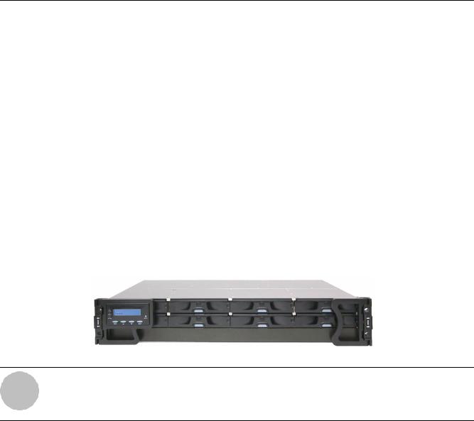
•The front section of the enclosure houses eight (8) hot-swap drive bays for SATA-II or backward compatible with SATA-I hard disk drives.
The subsystem is shown below:
Fig. 2.1 8-bay SATA RAID Subsystem
NOTICE!
On receiving and unpacking your subsystem, please check the package contents against the included unpacking checklist. If any modules appear to be missing, please contact your subsystem vendor immediately.
F.01U.027.797 | V2 | 2008.08 |
Bosch Security Systems |
RAID Subsystem DVA-08K | Installation Manual Introduction | en 9
2.2 |
Enclosure Chassis |
2.2.1 |
Chassis Overview |
|
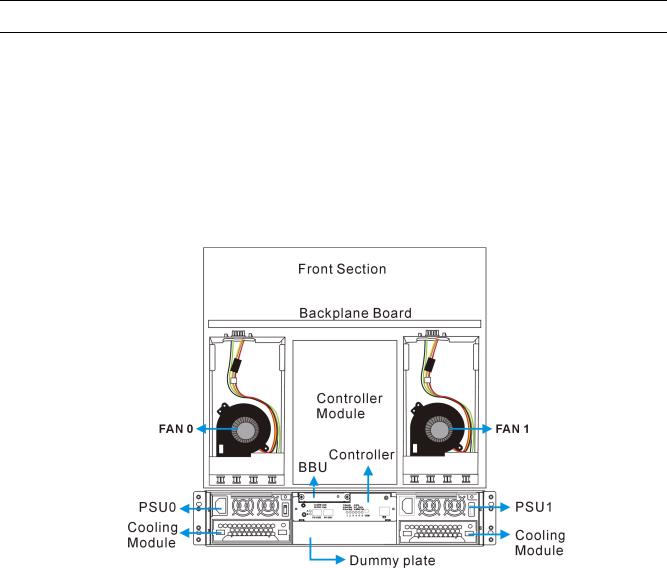
The RAID subsystem comes in a 2U metal chassis. A backplane board divides the enclosure |
|
internally into front and rear sections. The front section accommodates eight (8) drive trays |
|
(with their associated hard drives) and the rear section accommodates two (2) PSU modules, |
|
two (2) single-fan cooling modules, and a single RAID controller module. The two (2) forearm |
handles on the front of the subsystem enable you to easily insert/extract the chassis into/from a rack or cabinet. Pre-drilled mounting holes on the sides of the chassis allow you to attach separately purchased slide rails.
|
Fig. 2.2 Top View of the RAID subsystem |
|
|
|
CAUTION! |
|
When working with the subsystem, it is important to use tools with extreme care. Do not place |
|
tools or other items on top of the enclosure to help avoid damaging the chassis finish. |
|
|
2.2.2 |
Physical Dimensions |
|
The subsystem comes in a standard 2U, 19” chassis with the following dimensions: |
|
• Measured with forearm handles: 482mm x 88mm x 505mm (width x height x depth) |
|
• Measured without forearm handles: 446mm x 88mm x 490mm (width x height x depth) |
2.2.3 |
Front Panel Overview |
|
The front section of the subsystem features a 4 x 2 layout for eight (8) 3.5-inch disk drives and |
a foldable LCD keypad panel. The front panels of the RAID subsystems described in this manual are shown in Figure 2.3. A description of the front panel component is given below:
Bosch Security Systems |
F.01U.027.797 | V2 | 2008.08 |

10 en | Introduction |
RAID Subsystem DVA-08K | Installation Manual |
|
|
Fig. 2.3 Front View
The front panel is designed to accommodate the following components:
•Forearm handles with an LCD keypad panel: The LCD Panel mounted on the left handle shows system information and provides local access to the firmware-embedded configuration and monitoring utility.
•Drive bays with drive tray canisters: The drive bays are used to house the subsystem hard drives. The DVA-08K contains 8 drive bays with a blank plate covering the lower part of the front panel.
2.2.4 Hard Drive Numbering
The subsystem is housed in an enclosure that is 4 bays wide and 2 bays high. When viewed from the front, drive bays (slots) are numbered 1 to 8, from the left to the right, and then from the top to the bottom.
|
|
|
|
|
|
|
Fig. 2.4 Drive Bays Numbering Sequence |
||||
2.2.5 |
Rear Panel Overview |
||||
|
The rear section of the subsystems are accessed through the rear panel and is reserved for a |
||||
|
single RAID controller module, one (1) battery backup unit (BBU), two (2) power supply units |
||||
(PSUs), and two cooling fan modules.
The subsystem rear view is shown in Figure 2.5. A description of the rear panel component is given in the proceeding discussions:
Fig. 2.5 Rear View
The rear panel shown above is designed to accommodate the following components:
•RAID controller module: The controller module contains a controller main board and a pre-installed DDR DIMM module.
•Power Supply Unit (PSU): The PSU is used to provide power to the subsystem.
F.01U.027.797 | V2 | 2008.08 |
Bosch Security Systems |
RAID Subsystem DVA-08K | Installation Manual |
Introduction | en 11 |
|
|
i
•BBU module: A BBU provides the protective implementation to cached data; and, unless deselected when purchasing the subsystems, is installed into the module slot located at the upper left corner of the controller module.
•Cooling fan module: The redundant cooling fan module is used to ventilate the subsystem and to reduce the temperature within the subsystem.
NOTICE!
Each of the power supplies on the sides of the enclosure houses one cooling fan module in a removeable canister. When a power supply is removed, the cooling module is also removed. Therefore, replace the power supply unit as soon as possible whenever it becomes necessary. Cooling fan modules can be independently removed from the chassis without affecting PSU operation.
2.2.6 Backplane Board
An integrated backplane board separates the front and rear sections of the subsystem. The PCB board provides traces for logic level signal traces and low voltage power paths. It contains no user-serviceable components.
Bosch Security Systems |
F.01U.027.797 | V2 | 2008.08 |
12 en | Introduction RAID Subsystem DVA-08K | Installation Manual
2.3 Subsystem Components
All the active components on the subsystem can be accessed through either the front or rear panel. The modular design of the active components facilitates their easy installation and removal. Hot-swap mechanisms are incorporated to eliminate power surges and signal glitches that might occur while removing or installing these modules.
2.3.1 |
LCD Panel |
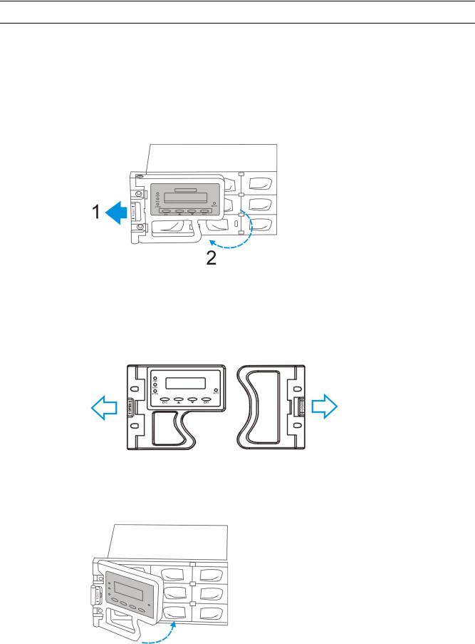
Fig. 2.6 Opening the Front Handle
The LCD panel shown in Figure 2.6 consists of a 16 characters x 2 rows LCD screen with push buttons, a mute button, and LED status indicators. The LCD front panel provides full access to all array configurations and monitoring. After powering up the subsystem, the initial screen will show the subsystem model name. A different name can be manually assigned to the subsystem or different drive arrays. This will enable easier identification in a topology consisting of numerous arrays.
Fig. 2.7 Front Panel Retention Latch
To access drive bays in the leftor right-hand side column, first flip the retention latches (see Figure 2.7) on the enclosure front handles, and then swing the handles to the leftand righthand sides. To close the handles (see Figure 2.8), swing the handles toward the system; gently press the handles until a click is heard. The latches will keep the handles in place.
Fig. 2.8 Closing the Front Handles
F.01U.027.797 | V2 | 2008.08 |
Bosch Security Systems |
RAID Subsystem DVA-08K | Installation Manual Introduction | en 13
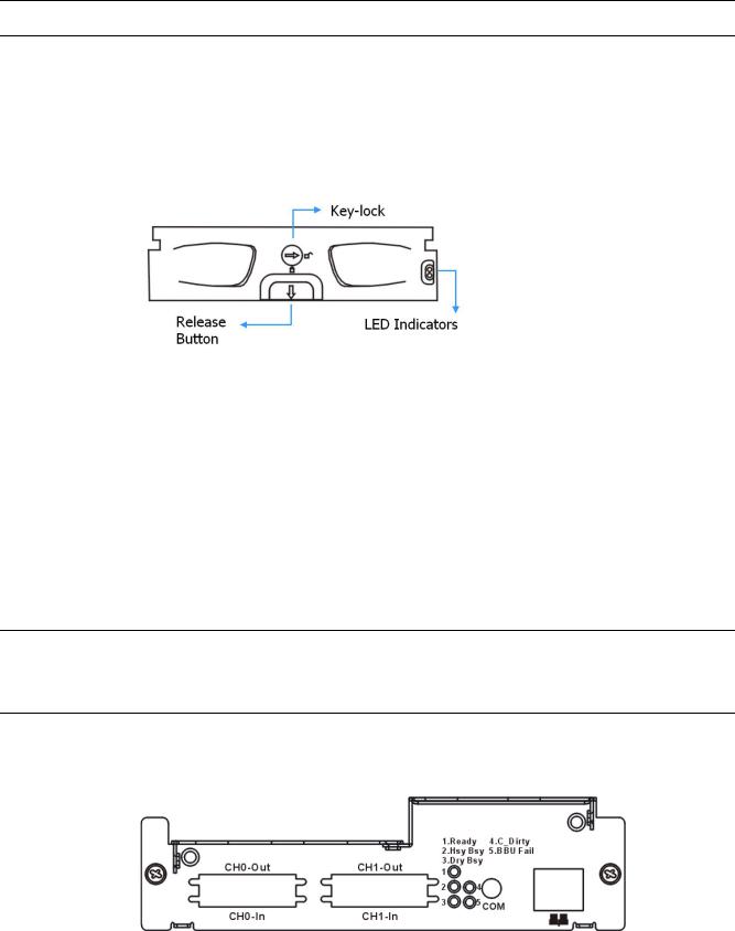
2.3.2 Drive Trays
The subsystem comes with 8 drive trays (see Figure 2.9) designed to accommodate separately purchased standard 1-inch pitch, 3.5-inch disk drives. The drive bays are accessed from the enclosure front. Two LED’s on the front of the tray are used to indicate the drive status. A keylock on each drive tray secures the hard drive in place, while an easily accessible release button ensures fast and efficient drive hot-swapping.
|
Fig. 2.9 Drive Tray Front View |
|
|
|
CAUTION! |
|
Be careful not to warp, twist, or contort the drive tray in any way (e.g., by dropping it or rest- |
|
ing heavy objects on it). The drive tray has been customized to fit into the drive bays in the |
|
subsystem. If the drive bay superstructure is deformed or altered, the drive trays may not fit |
|
into the drive bay. |
|
|
2.3.3 |
The RAID Controller Module |
|
The RAID controller module contains a main circuit board, a preinstalled 256MB capacity or |
|
above DDR RAM DIMM module, and the necessary support interfaces. The controller module |
|
contains no user-serviceable components. Except when replacing a faulty unit or installing/ |
|
upgrading the cache memory inside, the controller module should never be removed or |
|
opened. |
CAUTION!
Although the RAID controller can be removed, the only time you should touch the controller itself is to replace the memory module or to install the memory module. The RAID controller is built of sensitive components and unnecessary tampering can damage the controller.
Controller Module Interfaces
The subsystems provide external interfaces to host computers and management station(s) through the RAID controller’s rear-side faceplate as shown in Figure 2.10.
Fig. 2.10 Controller Module Faceplate
•Host Ports
SCSI-320 Host Ports: Two SCSI-320 host channels connect the subsystem to the host computers equipped with SCSI-320 compatible adapters through the dual-stack VHDCI connectors. The dual-stack connectors facilitate cascade connections for configurations such as host clustering or cascading with another RAID subsystem.
Bosch Security Systems |
F.01U.027.797 | V2 | 2008.08 |
14 en | Introduction |
RAID Subsystem DVA-08K | Installation Manual |
|
|
i
NOTICE!
This subsystems come with preset configurations for channel mode and channel ID settings, and should be sufficient for most applications.
•Ethernet Port
All controller modules on the subsystems come with a single 10/100BasedT RJ-45 Ethernet port. The Ethernet port is used for local or remote management through the network using the Bosch RAIDWatch GUI manager or Telnet protocol.
•COM Port
All controller modules come with one RS-232C (audio jack) serial port. The serial port is used for local access to the system-embedded configuration utility over the included serial port cable.
DIMM Module
The controller module comes with a preinstalled 256MB capacity or above DDR RAM DIMM module and can support a larger capacity up to 2GB. The DIMM module is mounted in an easily accessible location on the controller board. However, when the DIMM module is being changed, the controller module must be removed from the subsystem chassis.
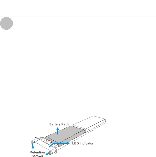
2.3.4 Battery Backup Unit
The Li-ION battery backup unit (BBU) module sustains cache memory for days after a power failure. It is installed on the upper left corner of the controller module in the rear of subsystem chassis. Please refer to Section 3 Hardware Installation for installation details.
Fig. 2.11 BBU Module
In accordance with international transportation regulations, the BBU module is only charged to between 35% and 45% of its total capacity when shipped. Therefore, when powering on the subsystem for the first time the BBU will begin to charge its batteries to their full capacity. It normally requires approximately twelve (12) hours for the battery to be fully charged. If the battery is not fully charged after twelve (12) hours (its LED is still flashing), there is a problem with the BBU module and you should contact your subsystem vendor immediately. While the battery is being charged, the LED on the BBU rear panel and the fifth LED on the controller module will flash.
You can check the status of the battery’s charge via Bosch RAIDWatch Manager or the firmware utility screen.
F.01U.027.797 | V2 | 2008.08 |
Bosch Security Systems |
RAID Subsystem DVA-08K | Installation Manual Introduction | en 15
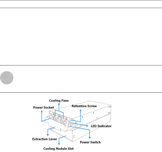
2.3.5 Power Supply Units
i
The SATA-based RAID subsystems are equipped with two (2) redundant, hot-swappable, 2U, 350W power supply unit (PSUs) modules. The PSU is permanently mounted into a 2U high (dual-level) bracket especially designed to house both the PSU and a cooling module mounted underneath. PSUs can be found on either side of the controller module.
Each PSU comes with a single power socket for power cord plug-in and a single power switch for you to turn the PSU on and off. Each PSU also comes with two embedded cooling fans to provide sufficient airflow to keep the PSU cool. A single LED is used to indicate the PSU status. A handle at the back of the PSU has been especially designed to enable you to remove the PSU from the subsystem while the system is still online. This should only be done if the PSU has failed and needs to be replaced.
NOTICE!
Hot-swapping the PSU also removes the cooling module at the lower slot.
A retention screw at the upper right corner of the PSU module is used to secure the PSU to the enclosure. If the PSU needs to be removed, the retention screw must be removed first. When installing a new PSU module, make sure that the retention screw has been firmly secured.
|
Fig. 2.12 PSU Module |
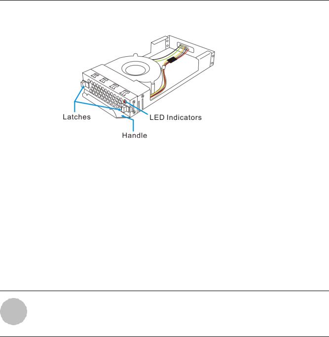
2.3.6 |
Cooling Fan Modules |
|
The SATA-based RAID subsystem is equipped with two 1U single-fan, redundant, hot-swappa- |
|
ble cooling modules shown in Figure 2.13. One 9.7cm fan is housed in each cooling module. |
These modules have been designed to generate a cooling flow from the front to the rear of the subsystem to extract the heat generated by the SATA hard drives. Two of the cooling fan modules are installed directly beneath the PSUs.
Bosch Security Systems |
F.01U.027.797 | V2 | 2008.08 |
16 en | Introduction |
RAID Subsystem DVA-08K | Installation Manual |
|
|
i
Fig. 2.13 Top View of a Cooling Fan Module
Advanced Fault-Preventative Operation
The cooling fan modules support dual-speed operation modes that help to protect the subsystem in the event of component failure or extreme working condition.
Intelligent Dual Speed Operation
The cooling fans operate with two rotation speeds. Under normal operating conditions, the cooling fans run at the low speed, which is sufficient for maintaining efficient airflow across components. Under the following conditions, cooling fans raise their rotation speed to increase the airflow:
1.Component Failure: if another cooling fan module, a PSU, or a temperature sensor fails, the remaining cooling fan(s) automatically raises its rotation speed.
2.Elevated Temperature: if the temperature breaches the upper threshold set for any of the interior temperature sensors, the cooling fans automatically raises its rotation speed.
3.During the subsystem initialization stage, the cooling fans operate at the high speed and return to lower speed once the initialization process is completed and no erroneous condition is detected.
NOTICE!
There are two values set for the upper temperature thresholds. One is set for event notification and the other triggering higher fan rotation speed. The preset value for event notification can be changed using the firmware-embedded configuration utility, while the fan speed trigger is not a user’s option.
F.01U.027.797 | V2 | 2008.08 |
Bosch Security Systems |

RAID Subsystem DVA-08K | Installation Manual Introduction | en 17
2.4 |
Subsystem Monitoring |
|
|
The SATA-based RAID subsystem comes with a number of different monitoring methods that |
|
|
provide you with continual updates on the status of the system and individual components. |
|
|
The following monitoring features are included in the subsystem. |
|
2.4.1 |
I2C Bus |
|
|
The following subsystem elements are interfaced to the RAID controller over a non-user-ser- |
|
|
viceable I2C bus: |
|
|
• |
Cooling fan modules |
|
• |
PSUs |
|
• |
Temperature sensors |
2.4.2 |
LED Indicators |
|
|
The following active components come with LEDs to indicate the status of the individual com- |
|
|
ponents: |
|
|
• |
RAID controller |
|
• |
LCD panel |
|
• |
Cooling fan module |
|
• |
PSU module |
|
• |
BBU module |
|
• |
Drive trays |
2.4.3 |
Firmware and Bosch RAIDWatch GUI |
|
|
Firmware: The firmware is pre-installed software that is used to configure the subsystem. The |
|
|
firmware can be accessed either through the LCD keypad panel or a terminal emulation pro- |
|
|
gram running on a management computer that is connected to the subsystem’s serial port. |
|
|
Bosch RAIDWatch: Bosch RAIDWatch is a premier Web-based graphical user interface (GUI) |
|
|
that can be installed on a remote computer and is used to access the array through LAN or the |
|
|
Internet. The manager communicates with the array via the connection of the existing host |
|
|
interface or Ethernet link to the RJ-45 LAN port. |
|
2.4.4 |
Audible Alarms |
|
|
The subsystems come with audible alarms that are triggered when certain active components |
|
|
fail or when certain (controller or subsystem) thresholds are exceeded. If you hear hastily |
|
|
repeated beep tones from the subsystems it is imperative that you immediately determine and |
|
|
rectify the problem. |
|
Event notification messages indicate the completion of or the condition when proceeding with array configuration tasks and are always accompanied by two or three successive and prolonged beeps.
CAUTION!
Failing to respond when a critical alarm is heard can lead to permanent damage of the subsystem. When an audible alarm is heard, rectify the problem as soon as possible.
Bosch Security Systems |
F.01U.027.797 | V2 | 2008.08 |

18 en | Introduction RAID Subsystem DVA-08K | Installation Manual
2.5 |
Hot-Swappable Components |
|
2.5.1 |
Hot-Swap Capabilities |
|
|
The subsystem comes with a number of hot-swappable components. A hot-swap component |
|
|
is one that can be exchanged while the subsystem is still online without affecting the opera- |
|
|
tional integrity of the subsystem. These components should only be removed from the subsys- |
|
|
tem when they are being replaced. At no other time should these components be removed |
|
|
from the subsystem. |
|
2.5.2 |
Components |
|
|
The following components are all hot-swappable: |
|
|
• Power supply units (PSUs) |
|
|
• |
Cooling fan modules |
|
• |
Hard drives |
|
• |
BBU module |
2.5.3 |
Normalized Airflow |
|
|
Proper subsystem cooling is referred to as “normalized” airflow. Normalized airflow ensures |
|
the sufficient cooling of the subsystem and is only attained when all components are properly installed. Therefore, a failed component should only be hot-swapped when a replacement is available. If a failed component is removed but not replaced, permanent damage to the subsystem can result.
F.01U.027.797 | V2 | 2008.08 |
Bosch Security Systems |

RAID Subsystem DVA-08K | Installation Manual Hardware Installation | en 19
3 |
Hardware Installation |
|
This chapter gives detailed instructions on how to install the subsystem. When installing the |
|
subsystem, it is necessary to mount the chassis into a rack or cabinet and to install hard |
|
drives and drive trays. Installation into a rack or cabinet should occur before the hard drives or |
|
drive trays are installed into the subsystem. Please confirm that you received all of the compo- |
|
nents listed on the Unpacking List that came with the subsystem before proceeding with the |
|
installation process. |
|
|
|
CAUTION! |
|
Please note that the installation instructions described in this chapter should be carefully fol- |
|
lowed to prevent any difficulties and damages to your system. |
|
|
3.1 |
Installation Prerequisites |
• Static free installation environment: The subsystems must be installed in a static-free environment to minimize the possibility of electrostatic discharge (ESD) damage. (See
Section 1 Warnings and Certifications).
• Component check: Before installing the subsystems, you should first check to see that you have received all the required components. If any items appear damaged, contact your vendor for a replacement.
• Hard drives: Hard drives must be purchased separately prior to the subsystem installation.
• Cabling:
– The subsystems requires an external VHDCI-to-VHDCI SCSI round cable to connect the subsystem to a host computer.
– One (1) audio-jack-to-DB9 cable is provided to facilitate the connection of the COM1 port for local terminal emulation access to the array.
– Two (2) power cords are provided for the power connections to the power sources.
– The RJ-45 Ethernet cable for network management connection is a user-supplied item.
• Memory module: If you wish to change the pre-installed memory module, a separately purchased module must be installed. Please contact your vendor for a different memory module or consult the list of compatible modules.
• Rack installation: The enclosure chassis can be installed into a rack cabinet using selfpurchased mounting rails. A printed copy of installation guide is provided with the slide rails package.
Bosch Security Systems |
F.01U.027.797 | V2 | 2008.08 |

20 en | Hardware Installation RAID Subsystem DVA-08K | Installation Manual
3.2 |
Safety Precautions |
3.2.1 |
Precautions and Instructions |
|
• Be sure the correct power range (100-120 or 220-240VAC) is supplied by your rack cabi- |
|
net, UPS device, or power outlet. |
|
• Thermal notice: All drive trays (even if they do not contain a hard drive) must be installed |
|
into the enclosure. Leaving a drive bay or module slot open will severely affect the airflow |
|
efficiency within the enclosure, and will consequently lead to system overheating. Keep a |
|
faulty module in place until you have a replacement unit and you are ready to replace it. |
|
• An enclosure without disk drives can weigh over 25 kilograms. Two (2) people are |
|
required to install or relocate the subsystem. To avoid damage to disk drives, drives |
|
should be removed from the enclosure before moving the subsystem. |
|
• Handle the system modules by the retention screws, extraction levers, or the modules |
|
metal frames/faceplates only. Avoid touching the PCB boards, connector pins, and sol- |
|
dered surfaces. |
|
• Airflow considerations: The subsystem requires an airflow clearance especially on the |
|
front and rear. For proper ventilation, a minimum of 2.5cm is required between the front |
|
of the enclosure and rack cover; a minimum of 5cm is required between the enclosure |
|
and end of the rack. |
|
• None of the covers or replaceable modules should be removed in order to maintain com- |
|
pliance with safety, emission, or thermal requirements. |
|
• Always secure every enclosure module by its retaining screws or make sure it is held in |
|
place by its latches. |
|
• Always make sure the subsystem has a safe electrical earth connection via power cords |
|
or chassis ground by the rack cabinet. |
|
• Be sure that the rack cabinet in which the subsystem chassis is to be installed provides |
|
sufficient ventilation channels and airflow circulation around the subsystem. |
|
• Provide a soft, clean surface to place your enclosure on before working on it. Servicing |
|
the enclosure on a rough surface may damage the finish of the chassis. |
|
• If it is necessary to transport the subsystem, repackage all disk drives separately. If using |
|
the original package material, all other modules can stay within the enclosure. |
3.2.2 |
Static-Free Installation |
|
The subsystem contains static-sensitive electronic components that can be damaged by |
|
improper handling and electrostatic discharge (ESD). To prevent ESD damage to any of the |
|
components, follow these precautions before touching or handling them: |
|
• Discharge the static electricity from your body by wearing an anti-static wristband or by |
|
touching a grounded metal surface. |
|
• Avoid carpets, plastic, vinyl, and styrofoam in your work area. |
|
• Handle all components by holding their edges or metal frame. Avoid touching PCB boards |
|
and connector pins. |
3.2.3 |
BBU Warnings and Precautions |
|
The BBU module sustains cache memory in the event of a power failure or in the unlikely event |
|
if both PSUs have failed. Having the protection to cached data by a BBU is highly recom- |
|
mended. The BBU provides additional data security and helps minimize the chance of data |
loss during power outage.
• Replace the BBU once it shows symptoms failing to hold the charge. Although the life expectancy of a BBU is determined by the times it has been charged or discharged, a BBU can approximately last for one year. If the battery recharge time is obviously longer than the suggested 12 hours, or if the fault LED is lit, replace the battery.
F.01U.027.797 | V2 | 2008.08 |
Bosch Security Systems |
RAID Subsystem DVA-08K | Installation Manual |
Hardware Installation | en 21 |
|
|
•Install or replace the BBU module only with a BBU module supplied by your subsystem vendor. Use of battery cells provided by another source will void our warranty.
•Always dispose of discharged or used batteries in an ecologically responsible manner. Dispose used BBUs at authorized battery disposal sites only.
•Do not use nor leave the BBU near a heat source or direct sunlight. Heat can melt the insulation and damage other safety features of battery cells, possibly leading it to acid leak and result in flames or explosion.
•Do not immerse the BBU in water nor allow it to get wet. Its protective features can be damaged. Abnormal chemical reactions may occur, possibly causing functional defects, acid leak, and other hazardous results.
•Do not disassemble or modify the BBU. If disassembled, the BBU could leak acid, overheat, emit smoke, burst and/or ignite.
•Do not pierce the BBU with a sharp object, strike it with a hammer, step on it, or throw it. These actions could damage or deform it, internal short-circuiting can occur, possibly causing functional defects, acid leaks, and other hazardous results.
•If the BBU leaks, gives off a bad odor, generates heat, becomes discolored or deformed, or in any way appears abnormal during use, recharging or storage, immediately remove it from the subsystem and stop using it. If this is discovered when you first use the BBU, return it to Bosch or your system vendor.
Bosch Security Systems |
F.01U.027.797 | V2 | 2008.08 |
Loading...