


DVA-12T
Table of contents
 Loading...
RAID Subsystem DVA-12T
DVA-12T iSCSI Premium Series
en Installation Manual


RAID Subsystem DVA-12T | Installation Manual Table of Contents | en 3
Table of Contents
1 Warnings and Certifications . . . . . . . . . . . . . . . . . . . . . . . . . . . . . . . . . . . . . . . . . . . . . . . . . . . . . . . . . . 5
1.1 Warning . . . . . . . . . . . . . . . . . . . . . . . . . . . . . . . . . . . . . . . . . . . . . . . . . . . . . . . . . . . . . . . . . . . . . . . . . . 5
1.2 Safety Precautions . . . . . . . . . . . . . . . . . . . . . . . . . . . . . . . . . . . . . . . . . . . . . . . . . . . . . . . . . . . . . . . . . 5
1.3 Certification . . . . . . . . . . . . . . . . . . . . . . . . . . . . . . . . . . . . . . . . . . . . . . . . . . . . . . . . . . . . . . . . . . . . . . 5
2 Introduction. . . . . . . . . . . . . . . . . . . . . . . . . . . . . . . . . . . . . . . . . . . . . . . . . . . . . . . . . . . . . . . . . . . . . . . 7
2.1 Product Overview . . . . . . . . . . . . . . . . . . . . . . . . . . . . . . . . . . . . . . . . . . . . . . . . . . . . . . . . . . . . . . . . . . 7
2.2 Enclosure Chassis . . . . . . . . . . . . . . . . . . . . . . . . . . . . . . . . . . . . . . . . . . . . . . . . . . . . . . . . . . . . . . . . . . 8
2.2.1 Chassis Overview . . . . . . . . . . . . . . . . . . . . . . . . . . . . . . . . . . . . . . . . . . . . . . . . . . . . . . . . . . . . . . . . . . 8
2.2.2 Front Panel Overview . . . . . . . . . . . . . . . . . . . . . . . . . . . . . . . . . . . . . . . . . . . . . . . . . . . . . . . . . . . . . . . 9
2.2.3 Hard Drive Numbering. . . . . . . . . . . . . . . . . . . . . . . . . . . . . . . . . . . . . . . . . . . . . . . . . . . . . . . . . . . . . . . 9
2.2.4 Rear Panel Overview . . . . . . . . . . . . . . . . . . . . . . . . . . . . . . . . . . . . . . . . . . . . . . . . . . . . . . . . . . . . . . . . 9
2.2.5 Backplane Board . . . . . . . . . . . . . . . . . . . . . . . . . . . . . . . . . . . . . . . . . . . . . . . . . . . . . . . . . . . . . . . . . . 10
2.3 Subsystem Components . . . . . . . . . . . . . . . . . . . . . . . . . . . . . . . . . . . . . . . . . . . . . . . . . . . . . . . . . . . . 10
2.3.1 Front Handles . . . . . . . . . . . . . . . . . . . . . . . . . . . . . . . . . . . . . . . . . . . . . . . . . . . . . . . . . . . . . . . . . . . . 10
2.3.2 Drive Trays. . . . . . . . . . . . . . . . . . . . . . . . . . . . . . . . . . . . . . . . . . . . . . . . . . . . . . . . . . . . . . . . . . . . . . . 11
2.3.3 The RAID Controller Module . . . . . . . . . . . . . . . . . . . . . . . . . . . . . . . . . . . . . . . . . . . . . . . . . . . . . . . . . 11
2.3.4 Controller Module Interfaces . . . . . . . . . . . . . . . . . . . . . . . . . . . . . . . . . . . . . . . . . . . . . . . . . . . . . . . . 12
2.3.5 DIMM Module . . . . . . . . . . . . . . . . . . . . . . . . . . . . . . . . . . . . . . . . . . . . . . . . . . . . . . . . . . . . . . . . . . . . 12
2.3.6 BBU . . . . . . . . . . . . . . . . . . . . . . . . . . . . . . . . . . . . . . . . . . . . . . . . . . . . . . . . . . . . . . . . . . . . . . . . . . . . 12
2.3.7 Power Supply Units. . . . . . . . . . . . . . . . . . . . . . . . . . . . . . . . . . . . . . . . . . . . . . . . . . . . . . . . . . . . . . . . 13
2.3.8 Cooling Modules . . . . . . . . . . . . . . . . . . . . . . . . . . . . . . . . . . . . . . . . . . . . . . . . . . . . . . . . . . . . . . . . . . 13
2.4 Subsystem Monitoring. . . . . . . . . . . . . . . . . . . . . . . . . . . . . . . . . . . . . . . . . . . . . . . . . . . . . . . . . . . . . . 14
2.4.1 I2C bus . . . . . . . . . . . . . . . . . . . . . . . . . . . . . . . . . . . . . . . . . . . . . . . . . . . . . . . . . . . . . . . . . . . . . . . . . 14
2.4.2 LED Indicators. . . . . . . . . . . . . . . . . . . . . . . . . . . . . . . . . . . . . . . . . . . . . . . . . . . . . . . . . . . . . . . . . . . . 14
2.4.3 Firmware (FW) . . . . . . . . . . . . . . . . . . . . . . . . . . . . . . . . . . . . . . . . . . . . . . . . . . . . . . . . . . . . . . . . . . . 14
2.4.4 Audible Alarms . . . . . . . . . . . . . . . . . . . . . . . . . . . . . . . . . . . . . . . . . . . . . . . . . . . . . . . . . . . . . . . . . . . 14
2.5 Hot-swappable Components . . . . . . . . . . . . . . . . . . . . . . . . . . . . . . . . . . . . . . . . . . . . . . . . . . . . . . . . . 15
2.5.1 Hot-swap Capabilities . . . . . . . . . . . . . . . . . . . . . . . . . . . . . . . . . . . . . . . . . . . . . . . . . . . . . . . . . . . . . . 15
2.5.2 Components . . . . . . . . . . . . . . . . . . . . . . . . . . . . . . . . . . . . . . . . . . . . . . . . . . . . . . . . . . . . . . . . . . . . . 15
2.5.3 Normalized Airflow . . . . . . . . . . . . . . . . . . . . . . . . . . . . . . . . . . . . . . . . . . . . . . . . . . . . . . . . . . . . . . . . 15
3 Hardware Installation . . . . . . . . . . . . . . . . . . . . . . . . . . . . . . . . . . . . . . . . . . . . . . . . . . . . . . . . . . . . . . 16
3.1 Introduction. . . . . . . . . . . . . . . . . . . . . . . . . . . . . . . . . . . . . . . . . . . . . . . . . . . . . . . . . . . . . . . . . . . . . . 16
3.2 Installation Prerequisites . . . . . . . . . . . . . . . . . . . . . . . . . . . . . . . . . . . . . . . . . . . . . . . . . . . . . . . . . . . 16
3.3 Safety Precautions . . . . . . . . . . . . . . . . . . . . . . . . . . . . . . . . . . . . . . . . . . . . . . . . . . . . . . . . . . . . . . . . 16
3.3.1 Precautions and Instructions . . . . . . . . . . . . . . . . . . . . . . . . . . . . . . . . . . . . . . . . . . . . . . . . . . . . . . . . 16
3.3.2 Static-free Installation . . . . . . . . . . . . . . . . . . . . . . . . . . . . . . . . . . . . . . . . . . . . . . . . . . . . . . . . . . . . . 17
3.4 General Installation Procedure . . . . . . . . . . . . . . . . . . . . . . . . . . . . . . . . . . . . . . . . . . . . . . . . . . . . . . . 17
3.5 Unpacking the Subsystem. . . . . . . . . . . . . . . . . . . . . . . . . . . . . . . . . . . . . . . . . . . . . . . . . . . . . . . . . . . 18
3.6 Rack/Cabinet Installation . . . . . . . . . . . . . . . . . . . . . . . . . . . . . . . . . . . . . . . . . . . . . . . . . . . . . . . . . . . 18
3.7 Drive Tray Installation . . . . . . . . . . . . . . . . . . . . . . . . . . . . . . . . . . . . . . . . . . . . . . . . . . . . . . . . . . . . . . 18
4 Subsystem Monitoring . . . . . . . . . . . . . . . . . . . . . . . . . . . . . . . . . . . . . . . . . . . . . . . . . . . . . . . . . . . . . 21
4.1 Subsystem Monitoring Overview. . . . . . . . . . . . . . . . . . . . . . . . . . . . . . . . . . . . . . . . . . . . . . . . . . . . . . 21
4.2 Status-indicating LEDs . . . . . . . . . . . . . . . . . . . . . . . . . . . . . . . . . . . . . . . . . . . . . . . . . . . . . . . . . . . . . 22
4.2.1 Brief Overview of the LEDs . . . . . . . . . . . . . . . . . . . . . . . . . . . . . . . . . . . . . . . . . . . . . . . . . . . . . . . . . . 22
4.2.2 Drive Tray LEDs . . . . . . . . . . . . . . . . . . . . . . . . . . . . . . . . . . . . . . . . . . . . . . . . . . . . . . . . . . . . . . . . . . . 22
4.2.3 Controller Module LEDs . . . . . . . . . . . . . . . . . . . . . . . . . . . . . . . . . . . . . . . . . . . . . . . . . . . . . . . . . . . . 23
4.2.4 Ethernet Port LEDs . . . . . . . . . . . . . . . . . . . . . . . . . . . . . . . . . . . . . . . . . . . . . . . . . . . . . . . . . . . . . . . . 23
4.2.5 BBU Module LED . . . . . . . . . . . . . . . . . . . . . . . . . . . . . . . . . . . . . . . . . . . . . . . . . . . . . . . . . . . . . . . . . . 24
4.2.6 PSU LEDs . . . . . . . . . . . . . . . . . . . . . . . . . . . . . . . . . . . . . . . . . . . . . . . . . . . . . . . . . . . . . . . . . . . . . . . 24
4.2.7 Cooling Module LEDs . . . . . . . . . . . . . . . . . . . . . . . . . . . . . . . . . . . . . . . . . . . . . . . . . . . . . . . . . . . . . . 25
4.3 Audible Alarm . . . . . . . . . . . . . . . . . . . . . . . . . . . . . . . . . . . . . . . . . . . . . . . . . . . . . . . . . . . . . . . . . . . . 25
4.3.1 Default Threshold Values. . . . . . . . . . . . . . . . . . . . . . . . . . . . . . . . . . . . . . . . . . . . . . . . . . . . . . . . . . . . 25
4.3.2 Failed Devices . . . . . . . . . . . . . . . . . . . . . . . . . . . . . . . . . . . . . . . . . . . . . . . . . . . . . . . . . . . . . . . . . . . . 26
4.4 I
5 Subsystem Connection and Operation . . . . . . . . . . . . . . . . . . . . . . . . . . . . . . . . . . . . . . . . . . . . . . . . . 27
5.1 Cabling . . . . . . . . . . . . . . . . . . . . . . . . . . . . . . . . . . . . . . . . . . . . . . . . . . . . . . . . . . . . . . . . . . . . . . . . . 27
5.2 Host Connection Topologies . . . . . . . . . . . . . . . . . . . . . . . . . . . . . . . . . . . . . . . . . . . . . . . . . . . . . . . . . 27
2
C Monitoring. . . . . . . . . . . . . . . . . . . . . . . . . . . . . . . . . . . . . . . . . . . . . . . . . . . . . . . . . . . . . . . . . . . . 26
Bosch Security Systems F.01U.027.798 | V1 | 2006.06

4 en | Table of Contents RAID Subsystem DVA-12T | Installation Manual
5.2.1 Direct-Attached, Single Connection . . . . . . . . . . . . . . . . . . . . . . . . . . . . . . . . . . . . . . . . . . . . . . . . . . . . 28
5.2.2 Connection through an Ethernet Switches . . . . . . . . . . . . . . . . . . . . . . . . . . . . . . . . . . . . . . . . . . . . . . 29
5.3 Power On . . . . . . . . . . . . . . . . . . . . . . . . . . . . . . . . . . . . . . . . . . . . . . . . . . . . . . . . . . . . . . . . . . . . . . . . 30
5.3.1 Check List. . . . . . . . . . . . . . . . . . . . . . . . . . . . . . . . . . . . . . . . . . . . . . . . . . . . . . . . . . . . . . . . . . . . . . . . 30
5.3.2 Power On Procedure . . . . . . . . . . . . . . . . . . . . . . . . . . . . . . . . . . . . . . . . . . . . . . . . . . . . . . . . . . . . . . . 30
5.3.3 Power On Enclosure . . . . . . . . . . . . . . . . . . . . . . . . . . . . . . . . . . . . . . . . . . . . . . . . . . . . . . . . . . . . . . . 30
5.3.4 Power On Status Check . . . . . . . . . . . . . . . . . . . . . . . . . . . . . . . . . . . . . . . . . . . . . . . . . . . . . . . . . . . . . 31
5.4 Power Off Procedure . . . . . . . . . . . . . . . . . . . . . . . . . . . . . . . . . . . . . . . . . . . . . . . . . . . . . . . . . . . . . . . 31
6 Subsystem Maintenance and Upgrading . . . . . . . . . . . . . . . . . . . . . . . . . . . . . . . . . . . . . . . . . . . . . . . . 32
6.1 Overview. . . . . . . . . . . . . . . . . . . . . . . . . . . . . . . . . . . . . . . . . . . . . . . . . . . . . . . . . . . . . . . . . . . . . . . . . 32
6.1.1 Maintenance . . . . . . . . . . . . . . . . . . . . . . . . . . . . . . . . . . . . . . . . . . . . . . . . . . . . . . . . . . . . . . . . . . . . . 32
6.1.2 General Notes on Component Replacement . . . . . . . . . . . . . . . . . . . . . . . . . . . . . . . . . . . . . . . . . . . . . 32
6.2 Replacing Controller Module Components . . . . . . . . . . . . . . . . . . . . . . . . . . . . . . . . . . . . . . . . . . . . . . 33
6.2.1 Controller Module Maintenance Overview . . . . . . . . . . . . . . . . . . . . . . . . . . . . . . . . . . . . . . . . . . . . . . . 33
6.2.2 Removing the Controller Module . . . . . . . . . . . . . . . . . . . . . . . . . . . . . . . . . . . . . . . . . . . . . . . . . . . . . . 33
6.2.3 Replacing the Controller Module . . . . . . . . . . . . . . . . . . . . . . . . . . . . . . . . . . . . . . . . . . . . . . . . . . . . . . 34
6.3 DIMM Module Replacement . . . . . . . . . . . . . . . . . . . . . . . . . . . . . . . . . . . . . . . . . . . . . . . . . . . . . . . . . . 34
6.3.1 DIMM Module Considerations . . . . . . . . . . . . . . . . . . . . . . . . . . . . . . . . . . . . . . . . . . . . . . . . . . . . . . . . 34
6.3.2 DIMM Module Replacement Procedure . . . . . . . . . . . . . . . . . . . . . . . . . . . . . . . . . . . . . . . . . . . . . . . . . 35
6.4 Replacing a Faulty BBU Module . . . . . . . . . . . . . . . . . . . . . . . . . . . . . . . . . . . . . . . . . . . . . . . . . . . . . . . 36
6.4.1 BBU Warnings and Precautions . . . . . . . . . . . . . . . . . . . . . . . . . . . . . . . . . . . . . . . . . . . . . . . . . . . . . . . 36
6.4.2 Procedure. . . . . . . . . . . . . . . . . . . . . . . . . . . . . . . . . . . . . . . . . . . . . . . . . . . . . . . . . . . . . . . . . . . . . . . . 36
6.5 Replacing a Failed PSU Module . . . . . . . . . . . . . . . . . . . . . . . . . . . . . . . . . . . . . . . . . . . . . . . . . . . . . . . 37
6.5.1 PSU Module Overview . . . . . . . . . . . . . . . . . . . . . . . . . . . . . . . . . . . . . . . . . . . . . . . . . . . . . . . . . . . . . . 37
6.5.2 Replacing the PSU Module. . . . . . . . . . . . . . . . . . . . . . . . . . . . . . . . . . . . . . . . . . . . . . . . . . . . . . . . . . . 37
6.6 Cooling Module Maintenance. . . . . . . . . . . . . . . . . . . . . . . . . . . . . . . . . . . . . . . . . . . . . . . . . . . . . . . . . 39
6.6.1 Cooling Module Overview. . . . . . . . . . . . . . . . . . . . . . . . . . . . . . . . . . . . . . . . . . . . . . . . . . . . . . . . . . . . 39
6.6.2 Replacing a Cooling Module. . . . . . . . . . . . . . . . . . . . . . . . . . . . . . . . . . . . . . . . . . . . . . . . . . . . . . . . . . 39
6.7 Replacing a Failed Hard Drive . . . . . . . . . . . . . . . . . . . . . . . . . . . . . . . . . . . . . . . . . . . . . . . . . . . . . . . . 40
6.7.1 Hard Drive Maintenance Overview . . . . . . . . . . . . . . . . . . . . . . . . . . . . . . . . . . . . . . . . . . . . . . . . . . . . . 40
6.7.2 Replacing a Hard Drive. . . . . . . . . . . . . . . . . . . . . . . . . . . . . . . . . . . . . . . . . . . . . . . . . . . . . . . . . . . . . . 41
7 Specifications. . . . . . . . . . . . . . . . . . . . . . . . . . . . . . . . . . . . . . . . . . . . . . . . . . . . . . . . . . . . . . . . . . . . . 43
7.1 Technical Specifications. . . . . . . . . . . . . . . . . . . . . . . . . . . . . . . . . . . . . . . . . . . . . . . . . . . . . . . . . . . . . 43
7.2 Controller Specifications . . . . . . . . . . . . . . . . . . . . . . . . . . . . . . . . . . . . . . . . . . . . . . . . . . . . . . . . . . . . 44
7.3 Drive Tray Specifications . . . . . . . . . . . . . . . . . . . . . . . . . . . . . . . . . . . . . . . . . . . . . . . . . . . . . . . . . . . . 45
7.4 Power Supply Specifications . . . . . . . . . . . . . . . . . . . . . . . . . . . . . . . . . . . . . . . . . . . . . . . . . . . . . . . . . 45
7.5 Cooling Module Specifications. . . . . . . . . . . . . . . . . . . . . . . . . . . . . . . . . . . . . . . . . . . . . . . . . . . . . . . . 45
7.6 RAID Management . . . . . . . . . . . . . . . . . . . . . . . . . . . . . . . . . . . . . . . . . . . . . . . . . . . . . . . . . . . . . . . . . 45
7.7 Fault Tolerance Management . . . . . . . . . . . . . . . . . . . . . . . . . . . . . . . . . . . . . . . . . . . . . . . . . . . . . . . . . 46
8 Spare Parts and Accessories . . . . . . . . . . . . . . . . . . . . . . . . . . . . . . . . . . . . . . . . . . . . . . . . . . . . . . . . . 47
8.1 Spare Parts. . . . . . . . . . . . . . . . . . . . . . . . . . . . . . . . . . . . . . . . . . . . . . . . . . . . . . . . . . . . . . . . . . . . . . . 47
8.2 Accessories . . . . . . . . . . . . . . . . . . . . . . . . . . . . . . . . . . . . . . . . . . . . . . . . . . . . . . . . . . . . . . . . . . . . . . 47
9 Pin Outs . . . . . . . . . . . . . . . . . . . . . . . . . . . . . . . . . . . . . . . . . . . . . . . . . . . . . . . . . . . . . . . . . . . . . . . . . 48
9.1 COM1 Cable: DB9 and Audio Jack Pin Outs . . . . . . . . . . . . . . . . . . . . . . . . . . . . . . . . . . . . . . . . . . . . . 48
9.2 Ethernet Port Pin Outs. . . . . . . . . . . . . . . . . . . . . . . . . . . . . . . . . . . . . . . . . . . . . . . . . . . . . . . . . . . . . . 48
9.3 Main Power . . . . . . . . . . . . . . . . . . . . . . . . . . . . . . . . . . . . . . . . . . . . . . . . . . . . . . . . . . . . . . . . . . . . . . 49
10 Index. . . . . . . . . . . . . . . . . . . . . . . . . . . . . . . . . . . . . . . . . . . . . . . . . . . . . . . . . . . . . . . . . . . . . . . . . . . . 51
F.01U.027.798 | V1 | 2006.06 Bosch Security Systems

RAID Subsystem DVA-12T | Installation Manual Warnings and Certifications | en 5
1 Warnings and Certifications
1.1 Warning
A shielded power cord is required in order to meet FCC emission limits and also to prevent
interference with nearby radio and television reception.
Use only shielded cables to connect I/O devices to this equipment. You are cautioned that
changes or modifications not expressly approved by the party responsible for compliance
could void your authority to operate the equipment.
1.2 Safety Precautions
Precautions and Instructions
• Prior to powering on the subsystem, ensure that the correct power range is being used.
• The RAID subsystem comes with 12 drive bays. Leaving any of these drive bays empty will
greatly affect the efficiency of the airflow within the enclosure, and will consequently
lead to the system overheating, which can cause irreparable damage.
• If a module fails, leave it in place until you have a replacement unit and you are ready to
replace it.
• Airflow Consideration: The subsystem requires an airflow clearance, especially at the
front and rear. The airflow direction is from front to back.
• Handle subsystem modules using the retention screws, eject levers, and the metal
frames/face plates. Avoid touching PCB boards and connector pins.
• To comply with safety, emission, or thermal requirements, none of the covers or replace-
able modules should be removed. Make sure that all enclosure modules and covers are
securely in place during operation.
• Be sure that the rack cabinet into which the subsystem chassis will be installed provides
sufficient ventilation channels and airflow circulation around the subsystem.
• Provide a soft, clean surface to place your subsystem on before working on it.
Servicing on a rough surface may damage the exterior of the chassis.
• If it is necessary to transport the subsystem, repackage all drives separately.
• Dual redundant controller models come with two controller modules that must be
installed into the subsystem. Single controller modules come with a single controller
module and a metal sheet is placed over the lower controller bay at the rear of the subsystem. Since single controller modules cannot be upgraded, this metal sheet should
NEVER be removed.
ESD Precautions
Observe all conventional anti-ESD methods while handling system modules. The use of a
grounded wrist strap and an anti-static work pad are recommended. Avoid dust and debris in
your work area.
1.3 Certification
FCC (applies in the U.S. and Canada)
FCC Class B Radio Frequency Interference Statement
This equipment has been tested and found to comply with the limits for a Class B digital
device, pursuant to Part 15 of the FCC Rules (47 CFR, Part 2, Part 15 and CISPR PUB. 22
Class B). These limits are designed to provide reasonable protection against harmful interference when the equipment is operated in a residential installation. This equipment generates,
uses, and can radiate radio frequency energy and, if not installed and used in accordance with
Bosch Security Systems F.01U.027.798 | V1 | 2006.06
6 en | Warnings and Certifications RAID Subsystem DVA-12T | Installation Manual
this user’s guide, may cause harmful interference to radio communications. However, there is
no guarantee that interference will not occur in a particular installation. If this equipment does
cause harmful interference to radio or television reception, which can be determined by turning the equipment off and on, you are encouraged to try to correct the interference by one or
more of the following measures:
• Reorient or relocate the receiving antenna.
• Increase the separation between the equipment and receiver.
• Connect the equipment into an outlet on a circuit different from that to which the
receiver is connected.
• Consult the dealer or an experienced radio/TV technician for help.
This device complies with Part 15 of FCC Rules. Operation is subject to the following two conditions: 1) this device may not cause harmful interference, and 2) this device must accept any
interference received, including interference that may cause undesired operation.
This device is in conformity with the EMC.
CB (Certified Worldwide)
This device meets the requirements of the CB standard for electrical equipment with regard to
establishing a satisfactory level of safety for persons using the device and for the area surrounding the apparatus. This standard covers only safety aspects of the above apparatus; it
does not cover other matters, such as style or performance.
F.01U.027.798 | V1 | 2006.06 Bosch Security Systems
RAID Subsystem DVA-12T | Installation Manual Introduction | en 7
2 Introduction
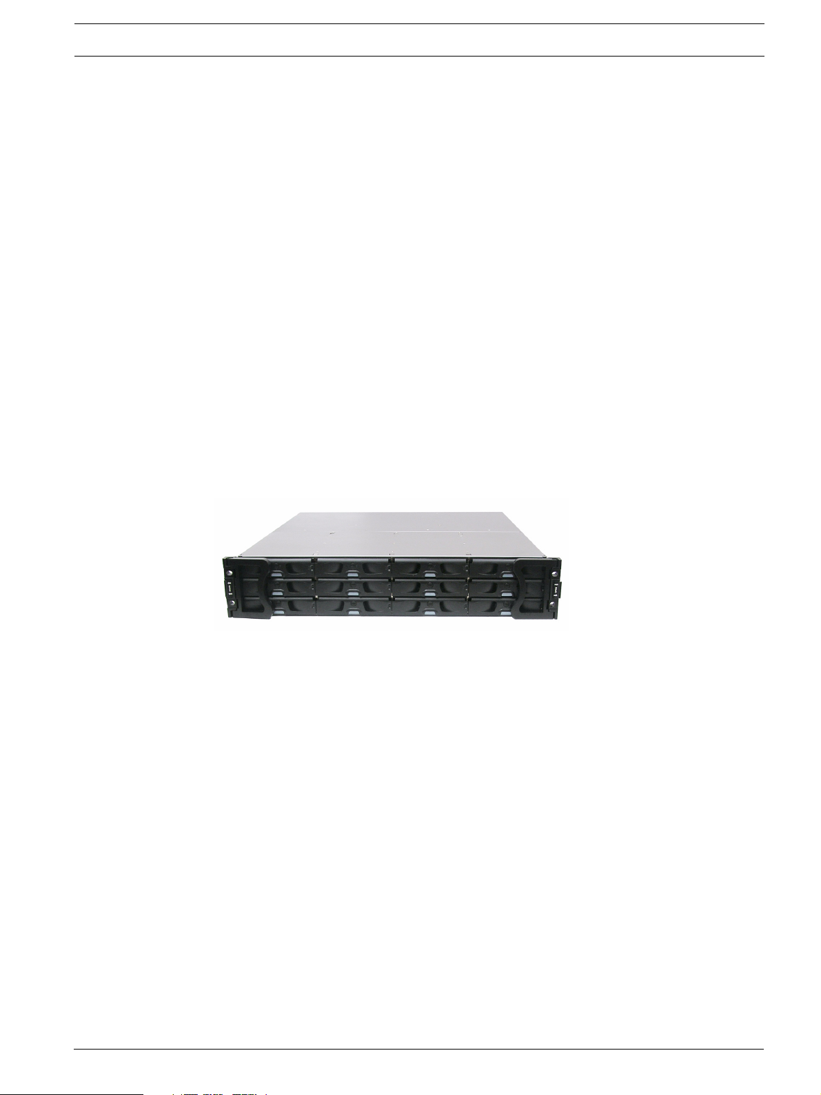
This hardware manual briefly introduces the DVA 12 T iSCSI-to-SATA-II storage subsystem
shown in Figure 2.1.
2.1 Product Overview
The RAID subsystem comes with two (2) Ethernet host ports capable of large I/O transfers
over iSCSI packets. The subsystems come in a 2U-profile rack-mountable chassis which
houses a RAID controller module featuring complete RAID configuration and maintenance
functionality. The subsystem’s operation is protected by redundant hot-swappable power supplies and cooling fan modules. Designed for high level of availability, all major components are
hot-replaceable including its Li-ION battery, and the RAID-protected disk drives.
The iSCSI storage supports the connection to network initiators compatible with the IETF
iSCSI standard (RFC 3720).
The subsystem facilitates data packaging, using the Internet SCSI (iSCSI) protocols, and
transmission of block I/Os over LANs. The subsystem is ideal for location-independent data
storage, backup, and retrieval. It combines the capabilities and block-level performance of
RAID storage with the high-speed, low-cost, and long-distance Ethernet networking technologies.
Configured arrays are easily combined with multiple ID/LUNs on host ports, turning massive
capacity into manageable units for data-sharing in a heterogeneous environment.
Fig. 2.1 RAID Subsystem DVA-12T
This high-density subsystem supports up to twelve (12) hot swappable, SATA-II hard drives in
a 2U-profile chassis. The subsystem is powered by the RAID controller board featuring the latest ASIC266 ASIC as the XOR engine and a pre-installed 1 GB DDR RAM DIMM module.
The controller board is housed in a metal canister and is referred to as the “controller module.” The controller module is comprised of a PCB board, a rear faceplate, and a metal canister. The controller module is accessed through the rear of the subsystem with the help of two
hand screws. An battery backup unit (BBU) can be installed in the upper left side of the controller module (when viewed from the rear of the subsystem). The BBU is hot swappable and
is accessed through the rear of the subsystem enclosure.
Two (2) RJ-45 connectors connect the RAID controller to network switches or Ethernet ports
of independent devices. Three (3) hot-swappable cooling modules protect the subsystem
from overheating, and two (2) hot-swappable power supply unit (PSU) modules provide constant power to the subsystem. The modular nature of the subsystem and the easy accessibility
to all major components ensure the ease of the subsystem maintenance.
A maximum of 31 units can be connected to the subsystem.
iSCSI Host Ports
Connectivity: - The iSCSI host ports are capable of 2 GBps Ethernet with full duplex transmission. Storage volumes are associated with simulated ID/LUNs on the host channels. These volumes then appear as iSCSI targets over the network. The connection of these host ports is
Bosch Security Systems F.01U.027.798 | V1 | 2006.06
8 en | Introduction RAID Subsystem DVA-12T | Installation Manual
identical with connecting Ethernet network devices either point-to-point to iSCSI initiators or
using Ethernet switches.
Other Concerns: - Subnet, gateway, and other access control mechanisms can be applied with
the iSCSI port connection.
The RAID subsystem supports connection through Ethernet networks to servers (iSCSI initiators) using iSCSI HBAs or SCSI packet processing software compliant with the IETF iSCSI
standard (RFC 3720).
Channels: - The SCSI-like ID/LUN mapping method enables users to associate storage volumes
with simulated IDs or LUNs on the host channels. On the drive side, all of the twelve (12)
SATA drives are connected each through a dedicated SATA channel. Each drive channel is
routed to an enclosure drive tray that is equipped with a standard SATA connector with hotswap capability. The methods used for assembling physical drives, fault management, and status monitoring are identical to that used with the traditional RAID storage.
NOTICE!
On receiving and unpacking your subsystem, please check the package contents against the
i
included Unpacking Checklist. If any modules are missing, please contact your subsystem vendor immediately.
2.2 Enclosure Chassis
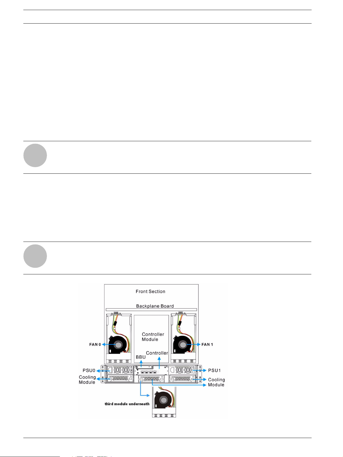
2.2.1 Chassis Overview
The RAID storage subsystem chassis is a 2U metal chassis that is divided into front and rear
sections. Key components are respectively accessed through front and rear panels. The predrilled mounting holes in the sides of the 2U RAID subsystem enclosure allow you to attach
separately purchased slide rails so that you can install the enclosure into a standard 19-inch
rack or enclosure cabinet.
NOTICE!
Components accessed through the front panel are referred to as “Front Panel Components”
i
and components accessed through the rear panel are referred to as “Rear Panel Components.”
Fig. 2.2 Locations of Key Components
F.01U.027.798 | V1 | 2006.06 Bosch Security Systems
RAID Subsystem DVA-12T | Installation Manual Introduction | en 9
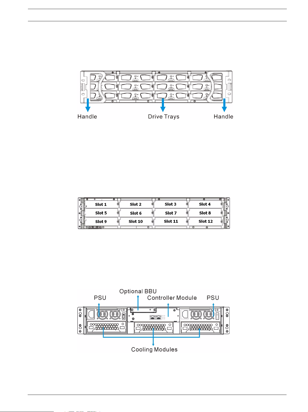
2.2.2 Front Panel Overview
The front section of the subsystem features a 4x3 layout for twelve (12) 3.5-inch drives. The
two (2) handles on the front of the subsystem enable you to easily insert/extract the chassis
into/from a rack or cabinet. The front panel of the RAID subsystem described in this manual is
shown in Figure 2.3. A description of each front panel component is given below:
Fig. 2.3 RAID Subsystem Front View
The front panel shown in Figure 2.3 accommodates the following components:
• Drive bays with drive tray canisters: The drive bays house the hard drives.
• Forearm handles: The subsystem has right and left handles for easier rackmounting and
handling.
2.2.3 Hard Drive Numbering
The front section of the RAID subsystem enclosure houses twelve (12) hard drives in a 4x3
configuration as shown in Figure 2.4. When viewed from the front, the drive bays (slots) are
numbered 1 to 12 from left to right, from top to bottom.
Fig. 2.4 Hard Drive Numbering
2.2.4 Rear Panel Overview
The rear section of the RAID subsystem is accessed through the rear panel and is reserved for
a single RAID controller module, one (1) BBU, two (2) power supply units (PSUs), and three
(3) cooling modules.
A rear view is of the subsystem is shown below. Descriptions of each rear panel component
are given below:
Fig. 2.5 RAID Subsystem Rear View
Bosch Security Systems F.01U.027.798 | V1 | 2006.06
10 en | Introduction RAID Subsystem DVA-12T | Installation Manual
The rear panel shown in Figure 2.5 accommodates the following components:
• RAID controller module: A controller board and a DDR RAM DIMM module are housed in
the controller module to provide the system RAID functionalities. (See Section 2.3.3 The
RAID Controller Module)
• BBU module: An BBU module sustains cache memory during a power shortage to prevent
data loss. (See Section 2.3.6 BBU)
• PSU modules: The hot-swappable PSUs provide power to the subsystem. A power switch
is located on the right of each PSU to turn the system on and off. (See
Section 2.3.7 Power Supply Units)
• Cooling modules: The redundant cooling modules ventilate the subsystem to reduce the
temperature within the subsystem. (See Section 2.3.8 Cooling Modules)
2.2.5 Backplane Board
An internal backplane board separates the front and rear sections of the RAID subsystem. The
PCB board consists of traces for logic level signals and low voltage power paths. It contains
no user-serviceable components.
CAUTION!
When inserting a removable module, DO NOT USE EXCESSIVE FORCE! Forcing or slamming a
module can damage the pins on the module connectors either on the module itself or on the
backplane. Gently push the module until it reaches the end of module slot. Feel the contact
resistance and use slightly more pressure to ensure the module connectors are correctly
mated. If the module comes with reject levers or retention screws, use them to secure the
module.
2.3 Subsystem Components
The RAID subsystem houses many active components and most of them can be accessed
through either the front or rear panel. The modular design of the active components facilitates
their easy installation and removal. Hot-swap mechanisms are incorporated to eliminate
power surges and signal glitches that might occur while removing or installing these modules.
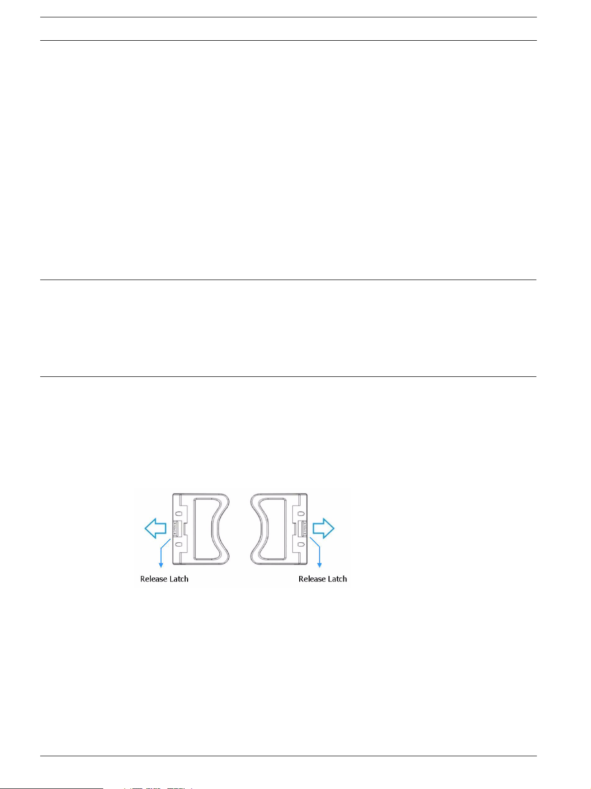
2.3.1 Front Handles
Fig. 2.6 Handles
A left and a right handle are installed on the front side of the chassis. Each handle has a
release latch to secure the position of the handle when closed. (See Figure 2.6) To access
drive bays in the left or right column behind the handles, first flip the release latch on the
enclosure front handles, and then swing the handles to the left and right sides, respectively.
(See Figure 2.7) To close the handles, swing the handles toward the system; gently press the
handles until a click is heard. The latches will keep the handles in place.
F.01U.027.798 | V1 | 2006.06 Bosch Security Systems
RAID Subsystem DVA-12T | Installation Manual Introduction | en 11
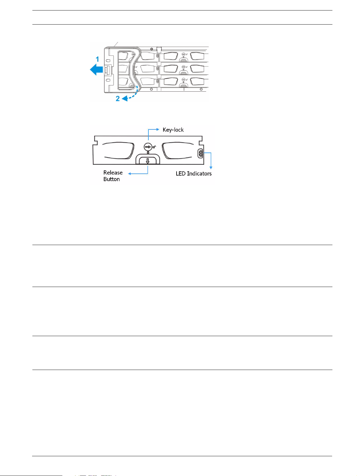
Fig. 2.7 Opening One of the Front Handles
2.3.2 Drive Trays
Fig. 2.8 Drive Tray Front View
The RAID subsystem comes with twelve (12) drive trays (see Figure 2.8) designed to accommodate separately purchased, standard 1-inch pitch, 3.5-inch disk drives. The drive bays are
easily accessible from the front of the enclosure. Two (2) LEDs on the front of the tray indicate the drive status. A key-lock on each drive tray secures the hard drive in place, while an
easily accessible release button ensures fast and efficient drive hot-swapping.
CAUTION!
Be careful not to warp, twist, or contort the drive tray in any way (e.g., by dropping it or resting heavy objects on it). The drive tray has been customized to fit into the drive bays in the
RAID subsystem. If the drive bay superstructure is deformed or altered, the drive trays may
not fit into the drive bay.
2.3.3 The RAID Controller Module
The RAID controller module contains a main circuit board, a preinstalled 1 GB capacity (or
above) DDR RAM DIMM module, and the controller module interfaces. The controller module
contains no user-serviceable components. Except when installing/upgrading the cache memory inside, the controller module should never be removed or opened.
CAUTION!
Although the RAID controller can be removed, the only time you should touch the controller
itself is to install the memory modules. The RAID controller is built of sensitive components
and unnecessary tampering can damage the controller.
The heart of the RAID controller subsystem is the iSCSI-to-SATA controller board. The controller comes with two (2) Ethernet host ports. The subsystem connects to the host through RJ45 connectors, while the connectors are also ready to connect to one or more network
switches, enabling access to your storage volumes in complex configurations such as datasharing or network zoning.
The docking connector at the rear of the controller board connects the controller module to
the backplane board. A DDR RAM DIMM socket is strategically placed in an easily accessible
location on the controller board for easy insertion of the DDR RAM DIMM module.
Bosch Security Systems F.01U.027.798 | V1 | 2006.06
12 en | Introduction RAID Subsystem DVA-12T | Installation Manual
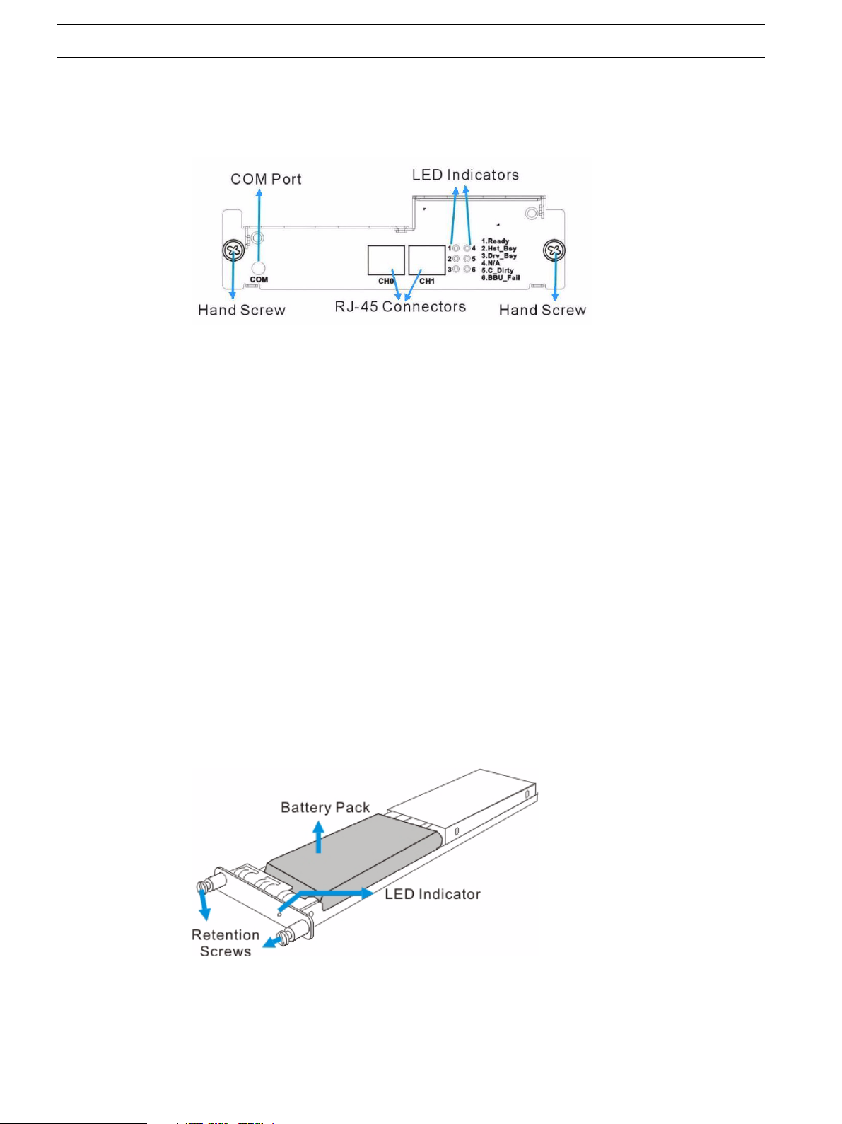
2.3.4 Controller Module Interfaces
All external interfaces that connect to external devices are located on the controller module
rear panel shown below. The interfaces are listed below.
Fig. 2.9 Controller Module Interfaces – 2-port version
• Host ports: Two (2) Gigabit Ethernet host ports (simulated and
indicated as CH0 and CH1 in the diagram shown above) connect the RAID subsystem to
the networked iSCSI initiators through two (2) RJ-45 connectors.
• COM port: The controller module comes with one (1) COM port.
This port is used for local access to the firmware embedded
configuration utility from a management computer.
• LED indicators: Five (5) LED indicators illustrate the system
statuses for system monitoring. Please see Section 4 Subsystem Monitoring for more
information.
• Hand screws: Two (2) hand screws located in the sides of the controller rear panel pro-
vide easy controller module installation and secure the controller module in place.
2.3.5 DIMM Module
The controller module comes with a preinstalled 1 GB capacity or above DDR RAM DIMM module. The DIMM module is placed in an easily accessed location on the controller board. However, when the DIMM module is being changed, the controller module must be removed from
the subsystem chassis.
2.3.6 BBU
An Li-ION battery backup unit (BBU) module (see Figure 2.10) can sustain cache memory for
days after a power failure. If you purchased a BBU, it will be installed on the upper left side of
the controller module in the rear of subsystem chassis.
Fig. 2.10 BBU Module
In accordance with international transportation regulations, the BBU module is only charged
to between 35% and 45% of its total capacity when shipped. Therefore, when powering on the
subsystem for the first time (see Section 5.3 Power On) the BBU will begin to charge its batter-
F.01U.027.798 | V1 | 2006.06 Bosch Security Systems
RAID Subsystem DVA-12T | Installation Manual Introduction | en 13
ies to their full capacity. It normally requires approximately twelve (12) hours for the battery
to be fully charged. If the battery is not fully charged after twelve (12) hours, there is a problem with the BBU module and you should contact your subsystem vendor immediately. While
the battery is being charged, the LED on the BBU rear panel and the sixth LED on the rear
panel of the controller module will flash. (See Section 4.2.5 BBU Module LED and
Section 4.2.6 PSU LEDsfor details on the LED indicators.)
You can check the status of the battery’s charge via RAIDWatch or the firmware utility screen.
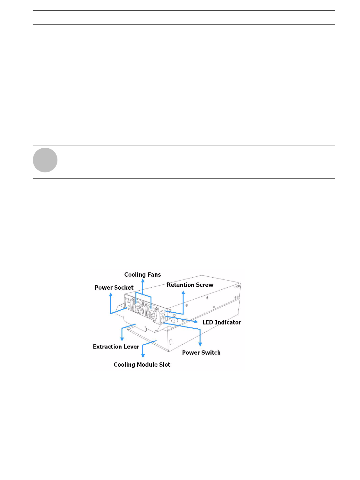
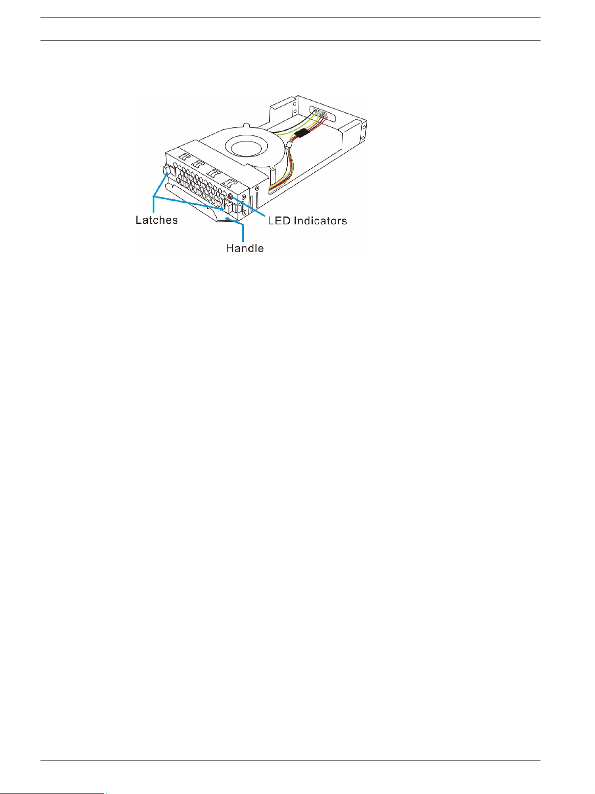
2.3.7 Power Supply Units
The RAID subsystem is equipped with two (2) redundant, hot-swappable, 350W PSUs, which
are accessed through the rear of the enclosure. The PSU is permanently mounted into a 2U
(dual-level) bracket especially designed to house both the PSU and a cooling module, which is
mounted in the lower part of the 2U bracket.
NOTICE!
Hot-swapping the PSU also removes the cooling module at the lower slot.
i
As shown in Figure 2.11, each PSU comes with a single power socket for power cord plug-in,
and a power switch on the right to turn the subsystem on and off. Two (2) embedded cooling
fans provide sufficient airflow to keep the PSU cool. A single LED indicates the PSU status.
When any power supply failure occurs, such as over-voltage or fan failure, the LED shines red.
A handle at the back of the PSU has been especially designed to enable you to remove the
PSU from the subsystem while the subsystem is online. This should only be done if the PSU
has failed and needs to be replaced.
A retention screw at the top of the PSU module secures the PSU to the enclosure. To remove
the PSU, the retention screw must be removed first. When installing a new PSU module, make
sure that the retention screw has been firmly secured.
Fig. 2.11 PSU Module
For the PSU specifications, please refer to Section 8 Spare Parts and Accessories.
2.3.8 Cooling Modules
The two subsystem models are all equipped with three (3) 1U, single-fan, hot-swappable cooling modules. They are installed in the cooling module slots located underneath the controller
module and PSU modules (see Figure 2.12.) The cooling fans operate at two (2) fan speed levels. When the subsystem is running in normal ambient temperature, the fans operate at the
lower speed. When the upper temperature threshold is exceeded, the fans automatically raise
Bosch Security Systems F.01U.027.798 | V1 | 2006.06
14 en | Introduction RAID Subsystem DVA-12T | Installation Manual
their rotation speed to generate more cooling air to extract the heat generated by the hard
drives.
Fig. 2.12 Cooling Module
2.4 Subsystem Monitoring
The RAID subsystem comes with a number of different monitoring methods that provide you
with continual updates on the status of the system and individual components. The following
monitoring features are included in the subsystem.
2.4.1 I2C bus
The following elements are interfaced to the RAID controller over a non-user-serviceable I2C
bus:
• Cooling modules
• Temperature sensors (for detecting the temperature of the backplane board and control-
ler board)
2.4.2 LED Indicators
The following active components come with LEDs to indicate the status of the individual component:
RAID controller (9 LEDs)
BBU module (1 LED)
Cooling modules (1 LED on each module)
PSU modules (1 LED on each module)
Drive trays (2 LEDs on each tray)
2.4.3 Firmware (FW)
The firmware is pre-installed software used to configure the subsystem. The latest firmware
functionalities include Task Scheduler, Intelligent Drive Handling, and Media Scan. Media
Scan handles low quality drives in both the degraded mode and during the rebuild process.
Maintenance tasks will then be performed on an entire array or specific hard drives. Various
options are user-configurable such as priority, start time, and execution intervals.
2.4.4 Audible Alarms
The RAID subsystem comes with audible alarms that are triggered when certain active components fail or when pre-configured (RAID controller or subsystem) thresholds are exceeded.
Whenever you hear an audible alarm from the RAID subsystem, it is imperative that you determine the cause and rectify the problem immediately.
F.01U.027.798 | V1 | 2006.06 Bosch Security Systems

RAID Subsystem DVA-12T | Installation Manual Introduction | en 15
Event notification messages indicate the completion or status of array configuration tasks and
are always accompanied by two (2) or three (3) successive and prolonged beeps.
CAUTION!
Failing to respond when an audible alarm is heard can lead to permanent damage of the RAID
subsystem. When an audible alarm is heard, rectify the problem as soon as possible.
2.5 Hot-swappable Components
2.5.1 Hot-swap Capabilities
The RAID subsystem comes with a number of hot-swappable components. A hot-swap component is one that can be exchanged while the subsystem is still online without affecting the
operational integrity of the subsystem. These components should only be removed from the
subsystem when they are being replaced. At no other time should these components be
removed from the subsystem.
2.5.2 Components
The following components are hot-swappable:
• Power supply units (PSUs)
• Cooling modules
• BBU module
• Hard drives
2.5.3 Normalized Airflow
Proper subsystem cooling is referred to as “normalized” airflow. Normalized airflow ensures
the sufficient cooling of the subsystem and is only attained when all components are properly
installed. Therefore, a failed component should only be hot-swapped when a replacement is
available. If a failed component is removed but not replaced, permanent damage to the subsystem can result.
Bosch Security Systems F.01U.027.798 | V1 | 2006.06

16 en | Hardware Installation RAID Subsystem DVA-12T | Installation Manual
3 Hardware Installation
3.1 Introduction
This chapter gives detailed instructions on how to install the subsystem. When installing the
subsystem, it is necessary to mount the chassis into a rack or cabinet and to install hard
drives and drive trays. Installation into a rack or cabinet should occur before the hard drives or
drive trays are installed into the subsystem. Please confirm that you received all of the components listed on the Unpacking List that came with the subsystem before proceeding with the
installation process.
CAUTION!
Please note that the installation instructions described in this manual should be carefully followed to prevent any difficulties and damages to your system.
3.2 Installation Prerequisites
1. Static-free installation environment: The RAID subsystem must be installed in a static-free
environment to minimize the possibility of electrostatic discharge (ESD) damage. (See
Section 3.3.2 Static-free Installation )
2. Component check: Before installing the RAID subsystem, you should first check to see
that you have received all the required components. (See Section 3.5 Unpacking the Sub-
system) If any items appear damaged, contact your vendor for a replacement.
3. Cabling: The RAID models all come with one (1) audio-jack-to-DB9 cable to facilitate the
connection of the COM port for terminal emulation management. Two (2) power cords
are provided for the power connections to the power sources. The RJ-45 cables for host
and external devices connections are user-supplied. Please see Section 5 Subsystem Con-
nection and Operation for sample topologies and configuration options.
4. Memory module: If you wish to change the pre-installed memory module, a separately purchased module must be installed. (See Section 6.3 DIMM Module Replacement)
5. Rack installation: The enclosure chassis can be installed into rack cabinet using separately
purchased mounting rails, rear-attached brackets, or Bosch’s slide rails (see
Section 3.6 Rack/Cabinet Installation).
3.3 Safety Precautions
3.3.1 Precautions and Instructions
1. Be sure the correct power range (100-120 or 220-240VAC) is supplied by your rack cabinet or power outlet.
2. Thermal notice: All drive trays (even if they do not contain a hard drive) must be installed
into the enclosure. Leaving a drive bay or module slot open will severely affect the airflow
efficiency within the enclosure, and will consequently lead to system overheating. Keep a
faulty module in place until you have a replacement unit and you are ready to replace it.
3. An enclosure without disk drives can weigh over 24 kilograms. Two (2) people are
required to install or relocate the subsystem. Drives should be removed from the enclosure before moving the subsystem.
4. Airflow considerations: The subsystem requires an airflow clearance especially on the
front and rear. For proper ventilation, a minimum of 2.5cm is required between the front
of the enclosure and rack cover; a minimum of 5cm is required between the enclosure
and end of the rack.
F.01U.027.798 | V1 | 2006.06 Bosch Security Systems

RAID Subsystem DVA-12T | Installation Manual Hardware Installation | en 17
5. Handle the system modules by the retention screws, eject levers, or the modules metal
frames/face plates only. Avoid touching the PCB boards and connector pins.
6. None of the covers or replaceable modules should be removed in order to maintain compliance with safety, emission, or thermal requirements.
7. Always secure every enclosure module by its retaining screws or make sure it is held in
place by its latches.
8. Always make sure the subsystem has a safe electrical earth connection via power cords
or chassis ground by the rack cabinet.
9. Be sure that the rack cabinet in which the subsystem chassis is to be installed provides
sufficient ventilation channels and airflow circulation around the subsystem.
10. Provide a soft, clean surface to place your enclosure on before working on it. Servicing
the enclosure on a rough surface may damage the finish of the chassis.
11. If it is necessary to transport the subsystem, repackage all disk drives separately.
3.3.2 Static-free Installation
Static electricity can damage the system’s electronic components. To prevent ESD damage to
any of the components, follow these precautions before touching or handling them:
• Discharge the static electricity accumulated in your body by wearing an anti-static wrist-
band.
• Avoid carpets, plastic, vinyl, and styrofoam in your work area.
• Handle all components by holding their edges or metal frames. Avoid touching the
exposed circuitry on PCB boards and connector pins.
3.4 General Installation Procedure
Following all the instructions provided below can save subsystem installation time. Detailed,
illustrated instructions for each component are given in the following sections.
1. Unpack: Unpack the subsystem and confirm that all the components on the Unpacking
Checklist have been included. (See Section 3.5 Unpacking the Subsystem)
2. Rack/Cabinet installation: If the subsystem is going to be installed in a rack or cabinet, it
should be installed prior to installing the hard drives. Installing the subsystem into a rack
or cabinet requires at least two (2) people. (See Section 3.6 Rack/Cabinet Installation)
3. Install drive trays: After the hard drives have been installed into the drive trays, the drive
trays must be installed into the enclosure itself. (See Section 3.7 Drive Tray Installation)
4. Cable connection: Use the power cables that came with the subsystem to connect the
subsystem to the main power source. Use self-purchased RJ-45 cables (see
Section 5 Subsystem Connection and Operation for more details) to connect host ports to
the network or external devices.
5. Power up: Once the components have been properly installed and all cables are properly
connected, you can power up the subsystem and configure the RAID array. (See
Section 5.3 Power On)
Bosch Security Systems F.01U.027.798 | V1 | 2006.06
Loading...