


 Loading...
AEC-PANEL19-UPS
AEC-PANEL19-4DR
|
|
|
|
|
|
|
|
|
|
|
|
en |
Installation manual |
||
de |
Installationshandbuch |
||
pl |
Instrukcja instalacji |
||
zh |
|
||
nl |
Installatiehandleiding |
||
ru |
Руководство по установке |
||
hu |
Telepítői kézikönyv |
||
pt |
Manual de instalação |
||
es |
Manual de instalación |
||

AEC-PANEL19 |
3 |
|
|
English
Deutsch
Polski
Nederlands
Русский
Magyar
Português brasileiro
Español latinoamericano
Bosch Sicherheitssysteme GmbH |
F.01U.097.256 | V 1.1 | 2008.12 |

AEC-PANEL19 - Installation manual |
en 5 |
|
|
Model variants
Two 19" mounting plate models are available for rack mounting the AMC2. Choose the variant which best suits your purposes based on the following considerations:
Choose mounting plate AEC-PANEL19-UPS (Order-No.: F.01U.066.193) if you wish to supply power using the PBC-60 or up to 2 rechargeable batteries. This variant comes with a cable kit which provides pre-mounted partial wiring for power supplies.
Choose mounting plate AEC-PANEL19-4DR (Order-No.: F.01U.066.194) if your power supply is external. In this case the rack mounting can hold up to 4 AMC devices in any combination
-for example:
-four AMC2s
-three AMC2s with one Extension board
-two AMC2s with two Extension boards
-one AMC2 with three Extension boards
-four Extension boards
This installation guide concerns itself primarily with the power supply variant (-UPS) before briefly treating the 4-DIN rail (- 4DR) variant.
Bosch Sicherheitssysteme GmbH |
F.01U.097.256 | V 1.1 | 2008.12 |
6 en |
AEC-PANEL19 - Installation manual |
|
|
AEC-PANEL19-UPS
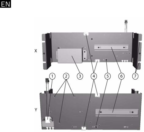
Rack mounting for AMC2, PBC-60 and rechargeable Batteries
Figure 1 Mounting plate for two AMC devices plus power supply
X = Front view; Y = Rear view
1.Power supply connections (pre mounted)
2.Screw sockets (pre mounted) for holding the PBC-60 power supply
3.Battery bracket
4.Cable channels
5.Grounding connection (pre mounted)
6.DIN Rails (pre mounted)
7.Cut-outs for fixing the mounting plate in 19’’ enclosures
F.01U.097.256 | V 1.1 | 2008.12 |
Bosch Sicherheitssysteme GmbH |
AEC-PANEL19 - Installation manual |
en 7 |
|
|
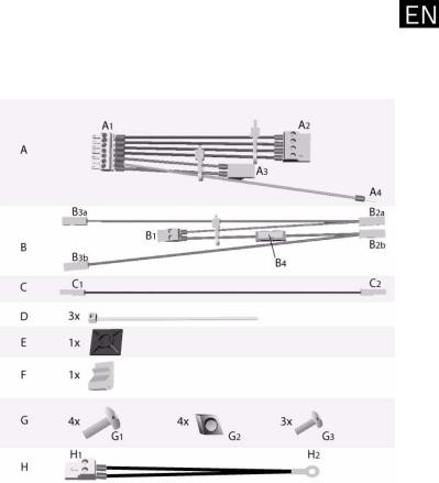
Cable kit for mounting plate AEC-PANEL19-UPS
The cable kit contains the following cable sets, which should be connected as described in Section Wiring the devices, Page 8 to their respective sockets.
Figure 2 Contents of the cable kit
A = pre mounted cable set for connecting the AMC to the PBC-60 power supply
B = pre mounted cable set for connecting the rechargeable Battery(-ies) to the UPS (uninterruptable power supply)
C = Connection cable for 24V-mode D = Cable ties
E = Fastener for temperature gauge
F = Clip for holding loose cable ends of B in 24V-mode G = Fixings
Bosch Sicherheitssysteme GmbH |
F.01U.097.256 | V 1.1 | 2008.12 |

8 en |
AEC-PANEL19 - Installation manual |
|
|
G1 = 4 Screws M6 x 16
G2 = 4 Cage nuts M6
G3 = 3 Screws M4 x 8
H = pre mounted cable set with temperature gauge
Wiring the devices
For mounting in the 19" enclosure
For mounting the power supply
Contained in the power supply kit
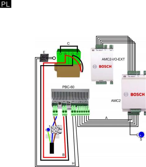
Figure 3 Wiring the devices
F.01U.097.256 | V 1.1 | 2008.12 |
Bosch Sicherheitssysteme GmbH |

AEC-PANEL19 - Installation manual en 9
|
NOTICE! |
i |
Figure 3 is a schematic diagram of interconnections within the |
19" frame, and does not reflect the actual positioning of devices |
|
|
on the mounting plate. |
|
|
|
|
|
NOTICE! |
i |
This section describes battery connections in 24V-mode. If you |
wish to run the AMC2 in 12V-mode, please follow Section 12V- |
|
|
mode variants, Page 11. |
|
|
|
|
CAUTION!
!Connect all devices in the order described below before connecting voltage.
1.Mount the AMC2 on the rail (6) on the front of the mounting plate (X), to the right of the battery bracket (3), befindet. The rail on the rear (Y) is available for a second AMC device.
2.Mount the power supply using the three screws G3 in the 3 screw sockets (2) at the rear(Y)
3.Stand the battery/-ies in the bracket (3).
4.Connecting the PBC-60 power supply to the AMC2 with cable set A:
a.Insert connector A1 into the 7-pole socket of the AMC2 marked POWER
b.Clip the grounding cable A4 under the fixing screw 5 on the mounting plate.
c.Pass the ends A2 and A3 of the cable set through the lower opening 4 to the rear side of the mounting plate.
d.At the PBC-60 power supply connect the A3 plug to the socket marked DC, and the A2 plug to the socket marked OK.
5.Connecting battery monitoring using cable set B:
a.Connect the B1 plug to the position marked BAT on the power supply.
b.Pass the rest of the cable ends through the upper opening 4 to the front side of the mounting plate.
c.Connect the B2b plug (red) to the positive terminal of the first battery.
d.Using cable C connect the negative terminal of the first battery to the positive terminal of the second battery.
Bosch Sicherheitssysteme GmbH |
F.01U.097.256 | V 1.1 | 2008.12 |
10 en |
|
AEC-PANEL19 - Installation manual |
|
|
|
|
e. |
Connect the B2a plug (black) to the negative terminal |
|
|
of the second battery. |
|
f. |
The ends B3a and B3b remain unused. Due to the pre- |
|
|
mounted connector no further insulation is necessary. |
|
6. Connecting the temperature gauge using cable set F: |
|
|
a. |
Connect the 2-pole plug F1 to the socket marked RTH |
|
|
on the PBC-60 power supply. |
|
b. |
Fix the cable with cable tie D to the fastener E, in such |
|
|
a way that the temperature gauge F2 is located close |
|
|
to the batteries. |
|
7. Connecting a further AMC-Device (here, as an example, an |
|
|
AMC2-16I-16O-EXT): |
|
|
a. |
Connect the RS485 slave interface of the second AMC |
|
|
device to the RS485 slave interface of the AMC2 |
|
|
marked RS-485EXT. |
|
b. |
Connect the data lines (pins 3 and 6) as well as the |
|
|
power lines (pins 1 and 2). |
|
|
|
i |
NOTICE! |
|
Connect readers and contacts in accordance with the AMC2 |
||
|
installation guide (Order-No.: F.01U.028.714). |
|
|
|
|
|
|
|
DANGER!
Before connecting the power supply, remove the fuse on the 3- pole connector (1)!
Do not replace the fuse until the connection process has been completed.
8.Connecting the power supply:
a.Clamp the neutral wire (blue) in the left screw terminal marked N on the mounting plate.
b.Clamp the live wire (brown) in the right hand terminal marked L1.
c.Attach the earth wire (yellow/green) to the mounting plate with the screw to the left of the clip.
CAUTION!
Trim the external power cables such that the earth wire (yellow/
!green) is at least 2cm (8/10") longer than the live wire (brown). This will ensure that, if the wires are accidentally pulled, that the voltage carrying wires will be disconnected first.
9.Mount the mounting plate in the 19" rack using the G1 screws and the G2 cage nuts.
F.01U.097.256 | V 1.1 | 2008.12 |
Bosch Sicherheitssysteme GmbH |
AEC-PANEL19 - Installation manual |
en 11 |
|
|
i |
NOTICE! |
Each mounting plate requires 4 rack units (U) and 88 horizontal |
|
|
pitchs (HP) in a 19" rack. |
|
|
|
12V-mode variants |
|
Figure 4 12V-modes with one or two rechargeable batteries |
|
|
|
NOTICE! |
i |
Figure 4 is a schematic diagram of interconnections within the |
19" frame, and does not reflect the actual positioning of devices |
|
|
on the mounting plate. |
12V-mode can be used with either one or two rechargeable batteries.
If using only one battery (left-hand picture) then connect it using pre mounted cable set B as follows:
1.Insert plug B1 into the power supply using the second socket from the left.
2.Pass the remaining cable ends through the upper cable channel 4 to the front of the mounting plate.
Bosch Sicherheitssysteme GmbH |
F.01U.097.256 | V 1.1 | 2008.12 |

12 en |
AEC-PANEL19 - Installation manual |
|
|
3.Connect terminal B2a (black) to the negative (-) pole of the battery, and B2b (red) to the positive (+) pole.
4.The cable ends B3a and B3b remain unused. Due to the
pre-mounted terminals there is no need for additional insulation. Fix the loose ends using clip F.
If using two batteries (right hand picture) then connect them as follows:
5.Insert plug B1 into the power supply using the second socket from the left.
6.Connect terminal B2a (black) to the negative (-) pole , and B2b (red) to the positive (+) pole of the battery.
7.Connect terminal B3a (black) to the negative (-) pole and B3b (red) to the positive (+) pole of the second battery.
NOTICE!
The setting for 12Vor 24V-mode is controlled by a switch on the power supply. First disconnect the unit from external voltage and then set the mode according to the following illustration.
i
F.01U.097.256 | V 1.1 | 2008.12 |
Bosch Sicherheitssysteme GmbH |

AEC-PANEL19 - Installation manual |
en 13 |
|
|
AEC-PANEL19-4DR
Mounting plate for up to 4 AMC devices
Figure 5 Mounting plate for up to 4 AMC devices
X = Front view; Y = Rear view
1.Grounding connections (pre mounted)
2.DIN rails (pre mounted)
3.Cable channels
4.Cut-outs for fixing the mounting plate in 19’’ enclosures
Bosch Sicherheitssysteme GmbH |
F.01U.097.256 | V 1.1 | 2008.12 |

14 en |
AEC-PANEL19 - Installation manual |
|
|
Connecting devices
Connecting an additional AMC device:
-Connect the RS485 slave interface of the second AMC device to the RS485 slave interface of the AMC2 marked
RS-485EXT.
You can provide each device with an individual power supply, or pass power through from one device to the next:
-If a second device receives its power supply from a first, then please connect the power lines (pin 1 and pin 2) as well as the data lines (pin 3 and pin 6).
NOTICE!
In general:
-If the devices have their own power supplies then the
i |
cable shielding should be grounded at one end only. The |
loose end should be insulated to prevent any inadvertent |
|
|
contact. |
-If one device passes power through to another, then the cable shielding should be grounded at both ends.
! |
CAUTION! |
Do not create any ground loops. |
|
|
|
|
|
i |
NOTICE! |
When connecting devices please consult the instructions and |
|
|
notices in their respective installation manual. |
|
|
F.01U.097.256 | V 1.1 | 2008.12 |
Bosch Sicherheitssysteme GmbH |

AEC-PANEL19 - Installationsanleitung |
de 15 |
|
|
Modell-Varianten
Das Montageblech für den AMC2 zum Einbau in ein 19" Gehäuse steht in zwei Ausführungen zur Verfügung.
Entsprechend des Verwendungszweckes sollte die geeignete Variante gewählt werden.
Nehmen Sie das Montageblech AEC-PANEL19-UPS (Bestell-Nr.: F.01U.066.193), wenn Sie die AMC Geräte mit der Stromversorgung PBC-60 sowie mit bis zu zwei Akkus versorgen wollen. Diese Variante wird mit einem Beipack ausgeliefert, der zum Teil vormontierte Kabelsätze zum Anschluss der Stromversorgung bereithält.
Wird die Stromversorgung extern geregelt, kann das Montageblech mit maximal vier AMC-Geräten bestückt werden. Verwenden Sie dazu die Variante AEC-PANEL19-4DR (BestellNr.: F.01U.066.194). Dazu können Sie die AMC-Geräte in beliebiger Konstellation anbringen:
-vier AMC2
-drei AMC2 mit einem Erweiterungsboard
-zwei AMC2 und zwei Erweiterungsboards
-einen AMC2 mit drei Erweiterungsboards
-vier Erweiterungsboards
Die vorliegende Montageanleitung beschreibt zunächst die Installation und die Anschaltungen zur Variante mit Stromversorgung und Akkus. Dann folgt die Beschreibung der Vier-Hutschienen-Variante.
Bosch Sicherheitssysteme GmbH |
F.01U.097.256 | V 1.1 | 2008.12 |

16 de |
AEC-PANEL19 - Installationsanleitung |
|
|
AEC-PANEL19-UPS
Montageblech für AMC2, PBC-60 und Akkus
Bild 1 Montageblech für zwei AMC-Geräte incl. Stromversorgung
X = Vorderansicht; Y = Rückansicht
1.Anschluss Stromversorgung (vormontiert)
2.Einsteckmuttern und -hülsen (vormontiert) zur Befestigung der Stromversorgung PBC-60
3.Batteriehaltevorrichtung
4.Öffnungen zur Kabelführung
5.Erdungsanschlüsse (vormontiert)
6.Hutschienen (vormontiert)
7.Öffnungen zur Befestigung des Rahmens in 19’’-Schränke
F.01U.097.256 | V 1.1 | 2008.12 |
Bosch Sicherheitssysteme GmbH |

AEC-PANEL19 - Installationsanleitung |
de 17 |
|
|
Beipack zum Montageblech AEC-PANEL19-UPS
Der Beipack enthält folgende Kabelsätze, die anhand der Beschreibung in Abschnitt Anschaltung der Geräte, Seite 18 auf die entsprechenden Schnittstellen aufgesteckt werden.
Bild 2 Inhalt des Beipacks
A = vormontierter Kabelsatz zum Anschluss des AMC’s an die Stromversorgung PBC-60
B = vormontierter Kabelsatz zum Anschluss der Akkus an die USV (unterbrechungsfreie Stromversorgung)
C = Verbindungskabel für 24V-Modus
D = Kabelbinder zur Fixierung der Kabelsätze
E = Klemme zur Fixierung des Temperaturfühlers
F = Klemme zur Fixierung der losen Kabelenden von B beim 24V-Modus
Bosch Sicherheitssysteme GmbH |
F.01U.097.256 | V 1.1 | 2008.12 |

18 de |
AEC-PANEL19 - Installationsanleitung |
|
|
G = Befestigungsmaterial
G1 = 4 Schrauben M6 x 16
G2 = 4 Käfigmuttern M6
G3 = 3 Schrauben M4 x 8
H = vormontierter Kabelsatz mit Temperaturfühler
Anschaltung der Geräte
zur Montage in das 19" Element.
zur Befestigung des Netzteils
im Beipack des Netzteils enthalten
Bild 3 Anschaltung der Geräte
F.01U.097.256 | V 1.1 | 2008.12 |
Bosch Sicherheitssysteme GmbH |

AEC-PANEL19 - Installationsanleitung |
de 19 |
|
|
|
HINWEIS! |
i |
Bild 3 zeigt schematisch die Anschlussbelegungen im 19" |
Rahmen und entspricht nicht der tatsächlichen Anordnung der |
|
|
Geräte auf dem Montagblech. |
|
|
|
|
|
HINWEIS! |
i |
Hier wird der Anschluss der Akkus im 24V-Modus beschrieben - |
sollten Sie den AMC2 im 12V-Modus betreiben, vgl. Sie die |
|
|
Angaben im Abschnitt 12V-Modus Varianten, Seite 21. |
|
|
|
|
|
VORSICHT! |
!Schließen Sie zunächst alle Geräte in der unten beschriebenen Reihenfolge an, bevor Sie Spannung anlegen.
1.Befestigen Sie den AMC2 auf der Hutschiene (6), die sich auf der Vorderseite des Montageblechs (X), rechts neben der Batteriehalterung (3), befindet. Für ein zweites AMCGerät steht die Hutschiene auf der Rückseite (Y) zur Verfügung.
2.Befestigen Sie die Stromversorgung mit den drei Schrauben G3 an den drei Einsteckhülsen (2) auf der Rückseite (Y)
3.Stellen Sie die Akkus in die Halterung (3).
4.Anschluss der Stromversorgung PBC-60 an den AMC2 mit dem Kabelsatz A:
a.Stecken Sie den Stecker A1 auf die 7-polige Schnittstelle des AMC2, die mit POWER bezeichnet ist, auf.
b.Das Erdungskabel A4 klemmen Sie unter die Befestigungsschraube 5 am Montageblech.
c.Führen Sie die Enden A2 und A3 des Kabelsatzes durch die untere Öffnung 4 zur Rückseite des Montageblechs.
d.An der Stromversorgung (PBC-60) stecken Sie den Stecker A3 auf die Schnittstelle, die mit DC bezeichnet ist und A2 auf die, die mit OK beschriftet ist, auf.
5.Anschluss der Akku-Überwachung mit dem Kabelsatz B:
a.Den Stecker B1 stecken Sie an die mit BAT beschriftete Position auf die Stromversorgung.
b.Führen Sie die restlichen Kabelenden durch die obere Öffnung 4 zur Vorderseite des Montageblechs.
Bosch Sicherheitssysteme GmbH |
F.01U.097.256 | V 1.1 | 2008.12 |

20 de |
AEC-PANEL19 - Installationsanleitung |
|
|
c.Der Stecker B2b (rot) auf den Plus-Pol des ersten Akkus.
d.Mit dem Kabel C verbinden Sie den Minus-Pol des ersten mit dem Plus-Pol des zweiten Akkus.
e.Stecker B2a (schwarz) wird auf den Minus-Pol des zweiten Akkus angeschlossen.
f.Die Enden B3a und B3b bleiben ungenutzt - durch die vorinstallierte Klemme ist keine zusätzliche Isolierung notwendig.
6.Anschluss des Temperaturfühlers mit dem Kabelsatz F:
a.Den 2-poligen Stecker F1 stecken Sie auf die Schnittstelle RTH der Stromversorgung PBC-60.
b.Befestigen Sie das Kabel mit einem Kabelbinder D an die Klemme E, so dass sich der Temperaturfühler F2 in der Nähe der Akkus befindet.
7.Anschluss eines weiteren AMC-Gerätes (hier als Beispiel ein AMC2-16I-16O-EXT):
a.Das zweite AMC-Gerät wird über die RS485-Slave- Schnittstelle des AMC2, die mit RS-485EXT beschriftet ist, verbunden. Am zweiten Gerät wird ebenfalls die RS485-Slaveschnittstelle benutzt.
b.Verbinden Sie neben den Datenleitungen (Pin 3 und 6) auch die Stromversorgung (Pin 1 und 2).
HINWEIS!
Der Anschluss der Leser und Kontakte erfolgt nach den Vorgaben des Installationshandbuchs für den AMC2 (Bestell-Nr.: F.01U.028.714).
GEFAHR!
Bevor Sie die Stromversorgung anschliessen, entfernen Sie die Sicherung der 3-poligen Klemme (1)!
Stecken Sie diese erst nach Beendigung der Anschlussarbeiten wieder auf.
8.Anschluss der Stromversorgung:
a.Befestigen Sie den Nullleiter (blau) unter die linke Schraubklemme, die auf dem Montageschild mit N bezeichnet ist.
b.Die Phase (braun) wird unter der rechten Schraubklemme, die mit L1 bezeichnet ist, befestigt.
c.Das Erdungskabel (gelb/grün) befestigen Sie mit der Schraube, die sich links der Klemme befindet, am Montageblech.
F.01U.097.256 | V 1.1 | 2008.12 |
Bosch Sicherheitssysteme GmbH |
AEC-PANEL19 - Installationsanleitung |
de 21 |
|
|
VORSICHT!
Kürzen Sie die Spannungzufuhr so ein, dass das Erdungskabel
!(gelb/grün) mindestens 2 cm länger bleibt als die stromführenden Kabel (blau und braun). Dies stellt bei einem Abriss sicher, dass die spannungsführenden Kabel zuerst abreißen.
9.Montieren Sie das Montageblech mit Hilfe der Schrauben G1 und Käfigmuttern G2 in den 19’’ Rahmen.
HINWEIS!
Für jedes Montageblech benötigen Sie 4 Höheneinheiten (HE) und 88 Teilungseinheiten (TE) im 19’’ Element.
12V-Modus Varianten
Bild 4 12V-Modus mit einer oder zwei Batterien
Bosch Sicherheitssysteme GmbH |
F.01U.097.256 | V 1.1 | 2008.12 |

22 de AEC-PANEL19 - Installationsanleitung
|
HINWEIS! |
i |
Bild 4 zeigt schematisch die Anschlussbelegungen im 19" |
Rahmen und entspricht nicht der tatsächlichen Anordnung der |
|
|
Geräte auf dem Montagblech. |
Der 12V-Modus kann wahlweise mit einem oder zwei Akkus betrieben werden.
Verwenden Sie nur einen Akku (wie in der linken Darstellung gezeigt), schließen Sie diesen mit dem vormontierten Kabelsatz B folgendermaßen an:
1.Den Stecker B1 stecken Sie an die zweite Position von links auf das Netzteil.
2.Führen Sie die restlichen Kabelenden durch die obere Öffnung 4 zur Vorderseite des Montageblechs.
3.Die Stecker B2a (schwarz) kommen auf den Minus-Pol und B2b (rot) auf den Plus-Pol des Akkus.
4.Die Enden B3a und B3b bleiben ungenutzt - durch die vorinstallierte Klemme ist keine zusätzliche Isolierung notwendig - fixieren Sie die losen Enden mit der Klemme F.
Bei der Verwendung von zwei Akkus (rechte Darstellung) verbinden Sie diese wie folgt:
5.Den Stecker B1 stecken Sie an die zweite Position von links auf das Netzteil.
6.Die Stecker B2a (schwarz) kommt auf den Minus-Pol und B2b (rot) auf den Plus-Pol des Akkus.
7.Die Enden B3a (schwarz) auf den Minus-Pol und B3b (rot) auf den Plus-Pol des zweiten Akkus.
F.01U.097.256 | V 1.1 | 2008.12 |
Bosch Sicherheitssysteme GmbH |

AEC-PANEL19 - Installationsanleitung |
de 23 |
|
|
HINWEIS!
Die Einstellung für den 12Voder 24V-Modus erfolgt über einen Schalter am Netzteil. Entfernen Sie zunächst die Spannungsversorgung und stellen Sie den Modus entsprechend der folgenden Darstellung ein.
i
Bosch Sicherheitssysteme GmbH |
F.01U.097.256 | V 1.1 | 2008.12 |

24 de |
AEC-PANEL19 - Installationsanleitung |
|
|
AEC-PANEL19-4DR
Montageblech für bis zu vier AMC-Geräte
Bild 5 Montageblech für bis zu vier AMC-Geräte
X = Vorderansicht; Y = Rückansicht
1.Erdungsanschlüsse (vormontiert)
2.Hutschienen (vormontiert)
3.Öffnungen zur Kabelführung
4.Öffnungen zur Befestigung des Rahmens in 19’’-Schränke
F.01U.097.256 | V 1.1 | 2008.12 |
Bosch Sicherheitssysteme GmbH |

AEC-PANEL19 - Installationsanleitung |
de 25 |
|
|
Anschaltung der Geräte
Anschluss eines weiteren AMC-Gerätes:
-Das zweite AMC-Gerät wird über die RS485-Slave- Schnittstelle des AMC2, die mit RS-485EXT beschriftet ist, verbunden. Am zweiten Gerät wird ebenfalls die RS485-
Slaveschnittstelle benutzt.
Sie können zu jedem Gerät eine separate Stromversorgung legen oder von einem Gerät zum nächsten weiterleiten.
-Wird das zweite Gerät vom ersten auch mit Strom versorgt, verbinden Sie die Geräte neben den Datenleitungen (Pin 3 und PIN 6) auch mit der Stromversorgung (Pin 1 und
PIN 2).
HINWEIS!
Generell gilt:
-Wenn die Geräte eine eigene Stromversorgung haben, wird die Kabelabschirmung nur an einer Seite aufgelegt.
Das nicht verbundene Ende sollte zum Schutz vor unbeabsichtigter Verbindung isoliert werden.
-Wenn ein Gerät durch ein anderes versorgt wird, wird die Kabelabschirmung an beiden Seiten aufgelegt.
VORSICHT!
!Achten Sie darauf, dass Sie keine Erdschleifen bilden.
i |
HINWEIS! |
Beachten Sie beim Anschluss der Geräte die Anleitungen und |
|
|
Hinweise in den entsprechenden Installationshandbüchern. |
|
|
Bosch Sicherheitssysteme GmbH |
F.01U.097.256 | V 1.1 | 2008.12 |
26 de |
AEC-PANEL19 - Installationsanleitung |
|
|
F.01U.097.256 | V 1.1 | 2008.12 |
Bosch Sicherheitssysteme GmbH |

AEC-PANEL19 - Instrukcja instalacji |
pl 27 |
|
|
Warianty modeli
Dostępne są dwa modele płyt montażowych 19" do montażu kontrolerów AMC2 w szafach typu rack. Należy wybrać odpowiedni wariant, biorąc pod uwagę następujące kwestie:
Płytę montażową AEC-PANEL19-UPS (nr katalogowy: F.01U.066.193) należy wybrać przy korzystaniu z zasilacza PBC60 lub maksymalnie 2 akumulatorów. W skład tego wariantu wchodzi zestaw kablowy z gotowym częściowym okablowaniem do podłączenia źródeł zasilania.
Płytę montażową AEC-PANEL19-4DR (nr katalogowy: F.01U.066.194) należy wybrać przy korzystaniu z zasilacza zewnętrznego. W tym przypadku w szafie typu rack można zamontować maksymalnie 4 urządzenia AMC w dowolnej kombinacji — na przykład:
-cztery kontrolery AMC2,
-trzy kontrolery AMC2 z jednym modułem rozszerzeń,
-dwa kontrolery AMC2 z dwoma modułami rozszerzeń,
-jeden kontroler AMC2 z trzema modułami rozszerzeń,
-cztery moduły rozszerzeń.
W niniejszej instrukcji instalacji skupiono się głównie na wariancie z zasilaczem (-UPS), z krótkim omówieniem wariantu z 4 szynami DIN (-4DR).
Bosch Sicherheitssysteme GmbH |
F.01U.097.256 | V 1.1 | 2008.12 |

28 pl |
AEC-PANEL19 - Instrukcja instalacji |
|
|
AEC-PANEL19-UPS
Montaż w szafie typu rack kontrolera AMC2, zasilacza PBC-60 i akumulatorów
Illustracja 1 Płyta montażowa na dwa urządzenia AMC oraz zasilacz
X = Widok z przodu; Y = Widok z tyłu
1.Połączenia modułu zasilacza (zamontowane fabrycznie)
2.Gniazda śrubowe (zamontowane fabrycznie) na zasilacz PBC-60
3.Wspornik akumulatora
4.Kanały kablowe
5.Złącze masy (zamontowane fabrycznie)
6.Szyny DIN (zamontowane fabrycznie)
7.Wycięcia do zamocowania płyty montażowej w obudowie 19’’
F.01U.097.256 | V 1.1 | 2008.12 |
Bosch Sicherheitssysteme GmbH |

AEC-PANEL19 - Instrukcja instalacji |
pl 29 |
|
|
Zestaw kablowy do płyty montażowej AEC-PANEL19-UPS
Zestaw kablowy zawiera następujące wiązki kabli, które należy podłączyć do odpowiednich gniazd w sposób opisany w
Punkt Okablowanie urządzeń, Strona 30.
Illustracja 2 Zawartość zestawu kablowego
A = gotowa wiązka kabli do podłączenia kontrolera AMC do zasilacza PBC-60
B = gotowa wiązka kabli do podłączenia akumulatora (lub akumulatorów) do zasilacza UPS
C = kabel połączeniowy dla trybu 24 V D = opaski kablowe
E = złącze czujnika temperatury
F =
Bosch Sicherheitssysteme GmbH |
F.01U.097.256 | V 1.1 | 2008.12 |
30 pl |
AEC-PANEL19 - Instrukcja instalacji |
|
|
G = elementy mocujące
G1 = 4 wkręty M6 x 16
G2 = 4 nakrętki koszyczkowe M6
G3 = 3 wkręty M4 x 8
H = gotowa wiązka kabli z czujnikiem temperatury
Do montażu w obudowie 19"
Do montażu zasilacza
Zawarte w zestawie zasilacza
Okablowanie urządzeń
Illustracja 3 Okablowanie urządzeń
F.01U.097.256 | V 1.1 | 2008.12 |
Bosch Sicherheitssysteme GmbH |
Loading...