


 Loading...
Access Management System
AMS Configuration and Operation
en |
Software manual |

Access Management System |
Table of contents | en |
3 |
|
|
|
Table of contents
1 |
Using Help |
6 |
2 |
About this documentation |
8 |
3 |
AMS System overview |
9 |
4 |
|
|
Licensing the system |
10 |
|
5 |
Configuring the calendar |
12 |
5.1 |
Defining Special days |
12 |
5.2 |
Defining Day models |
14 |
5.3 |
Defining Time models |
15 |
6 |
Configuring Divisions |
18 |
6.1 |
Assigning Divisions to devices |
18 |
6.2 |
Assigning Divisions to operators |
19 |
7 |
Configuring the IP addresses |
20 |
8 |
Using the Device Editor |
21 |
9 |
|
|
Configuring areas of access control |
23 |
|
9.1 |
Configuring areas for vehicles |
24 |
10 |
Configuring intrusion areas and panels |
26 |
10.1 |
Connecting the access control system to the intrusion panels |
26 |
10.1.1 |
Step 1: Connecting to the RPS API |
27 |
10.1.2 |
Step 2: Configuring the panel connections |
27 |
10.2 |
Creating authorization profiles for panels |
28 |
10.3 |
Assigning panel authorization profiles to cardholders |
29 |
11 |
Configuring operators and workstations |
30 |
11.1 |
Creating the workstations |
30 |
11.2 |
Creating workstation profiles |
31 |
11.3 |
Assigning workstation profiles |
32 |
11.4 |
Creating user (operator) profiles |
32 |
11.5 |
Assigning user (operator) profiles |
33 |
11.6 |
Setting passwords for operators |
34 |
12 |
Configuring cards |
36 |
12.1 |
Card Definition |
36 |
12.1.1 |
Creating and Modifying |
36 |
12.1.2 |
Activating / Deactivating card definitions |
37 |
12.1.3 |
Creating card data in the dialog manager |
38 |
12.2 |
Configuring card codes |
39 |
13 |
Configuring the controllers |
42 |
13.1 |
Configuring MACs and RMACs |
42 |
13.1.1 |
Configuring a MAC on the DMS server |
42 |
13.1.2 |
Preparing MAC server computers to run MACs and RMACs |
43 |
13.1.3 |
Configuring a MAC on its own MAC server |
44 |
13.1.4 |
Adding RMACs to MACs |
45 |
13.1.5 |
Adding further MAC/RMAC pairs |
47 |
13.1.6 |
Using the MAC installer tool |
48 |
13.2 |
Configuring the LACs |
50 |
13.2.1 |
AMC parameters and settings |
51 |
14 |
Configuring Entrances |
67 |
14.1 |
Entrances - introduction |
67 |
14.2 |
Creating entrances |
67 |
14.3 |
Configuring AMC terminals |
71 |
Bosch Security Systems |
Software manual |
2021-03 | 3.0.1.1 | |

4 en | Table of contents Access Management System
14.4 |
Predefined signals for door models |
77 |
14.5 |
Special entrances |
82 |
14.5.1 |
Elevators (DM07) |
82 |
14.5.2 |
Door models with intruder alarms (DM14) |
86 |
14.5.3 |
DIPs and DOPs (DM15) |
90 |
14.5.4 |
Mantrap door models |
91 |
14.6 |
Doors |
93 |
14.7 |
Readers |
96 |
14.7.1 |
Configuring random screening |
105 |
14.8 |
Access by PIN alone |
105 |
14.9 |
AMC extension boards |
107 |
15 |
Custom Fields for personnel data |
111 |
15.1 |
Previewing and editing Custom fields |
111 |
15.2 |
Rules for data fields |
113 |
16 |
Configuring Threat Level Management |
114 |
16.1 |
Concepts of Threat Level Management |
114 |
16.2 |
Overview of the configuration process |
114 |
16.3 |
Configuration steps in the device editor |
115 |
16.3.1 |
Creating a threat level |
115 |
16.3.2 |
Creating a Door security profile |
115 |
16.3.3 |
Creating a Reader security profile |
116 |
16.3.4 |
Assigning door and reader security profiles to entrances |
117 |
16.3.5 |
Assigning a threat level to a hardware signal |
118 |
16.4 |
Configuration steps in System data dialogs |
119 |
16.4.1 |
Creating a Person security profile |
119 |
16.4.2 |
Assigning a Person security profile to a Person Type |
119 |
16.5 |
Configuration steps in Personnel data dialogs |
120 |
17 |
Configuring Milestone XProtect to use AMS |
121 |
18 |
Defining access authorizations and profiles |
123 |
18.1 |
Creating access authorizations |
123 |
18.2 |
Creating access profiles |
123 |
19 |
Creating and managing personnel data |
125 |
19.1 |
Persons |
125 |
19.1.1 |
Card control or Building control options |
127 |
19.1.2 |
Extra info: Recording user-defined information |
128 |
19.1.3 |
Recording signatures |
128 |
19.1.4 |
Enrolling fingerprint data |
128 |
19.2 |
Companies |
130 |
19.3 |
Cards: Creating and assigning credentials and permissions |
130 |
19.3.1 |
Assigning cards to persons |
131 |
19.3.2 |
Printing badges |
132 |
19.3.3 |
Authorizations tab |
133 |
19.3.4 |
Other data tab: Exemptions and special permissions |
134 |
19.3.5 |
Authorizing persons to set Office mode |
135 |
19.3.6 |
Smartintego tab |
136 |
19.3.7 |
Creating an Alert card |
137 |
19.4 |
Temporary cards |
138 |
19.5 |
PIN codes for personnel |
139 |
19.6 |
Blocking access for personnel |
140 |
2021-03 | 3.0.1.1 | |
Software manual |
Bosch Security Systems |

Access Management System |
Table of contents | en |
5 |
|
|
|
19.7 |
Blacklisting cards |
142 |
19.8 |
Editing multiple persons simultaneously |
143 |
19.8.1 |
Group authorizations |
144 |
19.9 |
Changing the Division for persons |
145 |
19.10 |
Setting the area for persons or vehicles |
146 |
19.10.1 |
Procedure for resetting the location of all cardholders and vehicles |
146 |
19.11 |
Customizing and printing forms for personnel data |
147 |
20 |
Managing visitors |
148 |
20.1 |
Visitor data |
148 |
21 |
Managing parking lots |
153 |
21.1 |
Authorizations for several park zones |
153 |
21.2 |
Parking lot report |
154 |
21.3 |
Extended Car Park management |
154 |
22 |
Managing guard tours and patrols |
156 |
22.1 |
Defining guard tours |
156 |
22.2 |
Managing patrols |
157 |
22.3 |
Tour monitoring (formerly path control) |
158 |
23 |
Random screening of personnel |
160 |
24 |
Using the Event Viewer |
162 |
24.1 |
Setting filter criteria for time relative to the present |
162 |
24.2 |
Setting filter criteria for a time interval |
162 |
24.3 |
Setting filter criteria irrespective of time |
163 |
25 |
Using reports |
164 |
25.1 |
Reports: master data |
164 |
25.1.1 |
Reporting on vehicles |
166 |
25.2 |
Reports: system data |
167 |
25.3 |
Reports: authorizations |
168 |
26 |
Operating Threat Level Management |
170 |
26.1 |
Triggering and cancelling a threat alert via UI command |
170 |
26.2 |
Triggering a threat alert via hardware signal |
171 |
26.3 |
Triggering a threat alert via Alert card |
171 |
27 |
Backup and Restore |
172 |
27.1 |
Backing up the system |
172 |
27.2 |
Restoring a backup |
173 |
27.2.1 |
Restoring RMACs into a new installation |
175 |
|
Glossary |
176 |
Bosch Security Systems |
Software manual |
2021-03 | 3.0.1.1 | |
6 en | Using Help Access Management System
1 |
Using Help |
|
|
|
||
|
How to use this help file. |
|
|
|||
|
Tool bar buttons |
|
|
|
|
|
|
|
|
|
|
|
|
|
Button |
Function |
Description |
|
|
|
|
|
Hide |
|
Click this button to hide the navigation |
||
|
|
|
|
pane (Contents, Index and Search tabs). |
||
|
|
|
|
leaving only the help pane visible. |
||
|
|
|
|
|
||
|
|
Show |
|
When the Hide button is clicked it is |
||
|
|
|
|
replaced by the Show button. Click this |
||
|
|
|
|
button to reopen the Navigation pane. |
||
|
|
|
|
|
||
|
|
Back |
|
Click this button to move back through |
||
|
|
|
|
the chain of topics most recently |
|
|
|
|
|
|
viewed. |
|
|
|
|
|
|
|||
|
|
Forward |
Click this button to move forward again |
|||
|
|
|
|
through the same chain of topics |
|
|
|
|
|
|
|
|
|
|
|
|
Click this button to print. Choose |
|
||
|
|
|
|
between “Print the selected topic,” and |
||
|
|
|
|
“Print the selected heading and all |
||
|
|
|
|
subtopics”. |
|
|
|
|
|
|
|
|
|
|
Tabs |
|
|
|
|
|
|
Contents |
This tab displays a hierarchical table-of- |
||||
|
|
|
contents. Click a book icon |
to open it |
||
|
|
|
|
and then click on a topic icon |
to view |
|
|
|
|
the topic. |
|
|
|
|
Index |
This tab displays an index of terms in |
|
|||
|
|
|
alphabetical order. Select a topic from the |
|||
|
|
|
list or type in a word to find the topic(s) |
|||
|
|
|
containing it. |
|
|
|
|
Search |
Use this tab to find any text. Enter text in the |
||||
|
|
|
field and then click button: List Topics to |
|||
|
|
|
find topics that contain all the words |
|
||
|
|
|
entered. |
|
|
|
Resizing the help window
Drag the corner or edge of the window to the desired size.
Further conventions used in this documentation
–Literal text (labels) from the UI appears in bold. E.g. Tools, File, Save As...
–Sequences of clicks are concatenated using the > character (the greater-than sign). E.g. File > New > Folder
–Changes of control-type (e.g. menu, radio-button, check box, tab) within a sequence are indicated just before the label of the control.
E.g. Click menu: Extra > Options > tab: View
–Key combinations are written in two ways:
2021-03 | 3.0.1.1 | |
Software manual |
Bosch Security Systems |

Access Management System |
Using Help | en |
7 |
|
|
|
–Ctrl+Z means hold down the first key while pressing the second
–Alt, C means press and release the first key, then press the second
–The functions of icon buttons are added in square brackets after the icon itself. E.g. [Save]
Bosch Security Systems |
Software manual |
2021-03 | 3.0.1.1 | |

8 en | About this documentation Access Management System
2 About this documentation
This is the main software manual for the Access Management System.
It covers the use of the main dialog manager program, hereafter referred to as AMS
–The configuration of an access control system in AMS .
–The operation of the configured system by system operators.
Related documentation
The following are documented separately:
–The installation AMS and its auxiliary programs.
–The operation of AMS - Map View.
2021-03 | 3.0.1.1 | |
Software manual |
Bosch Security Systems |

Access Management System |
AMS System overview | en |
9 |
|
|
|
3 |
AMS System overview |
Access Management System is a powerful, pure access control system, which performs solo or in concert with BVMS, the Bosch flagship video management system.
Its power stems from its unique balance of leading-edge and proven technologies:
–Designed for usability: practical user interface with drag-and-drop Map View, and streamlined biometric enrollment dialogs.
–Designed for data security: supporting the latest standards (EU-GDPR 2018), operating systems, databases and encrypted system interfaces.
–Designed for resilience: middle-layer main access controllers provide automatic failover and replenishment of local access controllers in case of network failure.
–Designed for the future: regular updates and a pipeline full of innovative enhancements.
–Designed for scalability: offering low to high entry levels.
–Designed for interoperability: RESTful APIs, with interfaces to Bosch video management, event handling and specialized partner solutions.
–Designed for investment-protection: allowing you to build on, but boost the efficiency of, your installed access-control hardware.
Bosch Security Systems |
Software manual |
2021-03 | 3.0.1.1 | |

10 en | Licensing the system Access Management System
4 Licensing the system
Prerequisites
–The system has been installed successfully.
–You are logged onto the AMS server computer, preferably as Administrator.
Procedure for purchased licenses
Prerequisites: You have purchased licenses based on the computer signature of this computer. Contact your sales representative for instructions.
Dialog path: Configuration > Licenses
1.Log onto AMS, the Access Management System.
2.On the License tab, click the Start License Manager button.
–Effect: The License Manager dialog box is displayed.
3.Select the check boxes for the software package, the features, and the expansions that you have ordered. For the expansions, enter also the number of units required.
4.Click the Activate… button.
–Effect: The License Activation dialog box is displayed containing your computer signature.
5.Write down the computer signature or copy and paste it into a text file.
6.On a computer with Internet access, enter the following URL into your browser: https://activation.boschsecurity.com
If you do not have an account to access the Bosch License Activation Center, either create a new account and log on (recommended), or click the link to activate a new license without logging on. Note that for SMA (software maintenance agreement) licenses an account is always required. An account has the further advantage of keeping track of all your activations for future reference.
Follow the instructions on the website to obtain the License Activation Key.
7.Return to the software. In the License Activation dialog box, type or paste in the License Activation Key obtained from the Bosch License Activation Center and click the Activate button.
–Effect: The software packages are activated for the computer.
Notice!
Effects of hardware and software changes
Changes to the hardware of the your server may invalidate your license and cause the software to stop functioning. Please check with technical support before making changes to the server.
Procedure for Demonstration Mode
Demonstration Mode licenses all system features for a limited period. Use Demonstration Mode only in non-production environments to try out features before purchasing them.
1.Log onto the Access Manager
2.Navigate to Configuration > Licenses
3.Click the button Activate Demo Mode
4.Verify that the features are listed in the Licenses dialog window.
Demonstration mode is activated for 5 hours. Note that the expiration time is displayed near the top of the Licenses dialog, and in the title bar of most dialog windows.
2021-03 | 3.0.1.1 | |
Software manual |
Bosch Security Systems |
Access Management System |
Licensing the system | en 11 |
|
|
Bosch Security Systems |
Software manual |
2021-03 | 3.0.1.1 | |

12 en | Configuring the calendar Access Management System
5 Configuring the calendar
The scheduling of access control activities is governed by time models.
A time model is an abstract sequence of one or more days, each of which is described by a day model.
Time models control activities when they are applied to the underlying calendar of the access control system.
The calendar of the access control system is based on the calendar of the host computer’s operating system, but amplifies it with special days that are freely defined by the administrator of the access control system.
Special days can be fixed to a particular date in the calendar or defined relative to a cultural event, such as Easter. They can be recurring or not.
The configuration of an effective calendar for your access control system consists of the following steps.
1.Define the special days of the calendar that applies to your location.
2.Define day models that describe the active and inactive periods of each type of day. For instance, the day model for a public holiday will be different from that of a normal working day. Shift work will also effect the type and number of day models you require.
3.Define time models consisting of one or more day models.
4.Assign time models to cardholders, authorizations and entrances.
5.1Defining Special days
When this is opened, a list appears in the top list field of the dialog containing all specified holidays. Please note that all holiday dates shown relate only to the current year. However, the calendar is updated from year to year in accordance with the data entered.
Beneath the list there are different dialog fields for the creation of new special days and for the change or deletion of existing special days. To add a new special day, at least three of these input fields must contain data. First a description and a date must be entered in the respective fields. Thirdly the class to which this special day belongs must be selected from the appropriate selective list.
2021-03 | 3.0.1.1 | |
Software manual |
Bosch Security Systems |

Access Management System |
Configuring the calendar | en 13 |
|
|
The date is specified in several steps. First of all, a base date is entered in the Date field. At this point the date describes an event in the current year. If the user now specifies the frequency of a periodic return in the selection list next to the date field, the parts of the date set by the periodicity are replaced by "wildcards" (*).
once |
__.__.____ |
|
|
once per year |
__.__.**** |
|
|
once per month for a period of a year |
__.**.____ |
|
|
once per month in every year |
__.**.**** |
|
|
depending on Easter |
**.**.**** |
|
|
Holidays that depend on Easter are not specified with their date, but with the difference in days from Easter Sunday. The date of the Easter Sunday in the current year is indicated in the Date within this year field , and the variance of this date is entered or selected in the Days to add field. The maximum number of days is 188, so with adding or subtracting you can define every day of the year.
The other data, e.g. the week day of the holiday, are optional. Please note that the week day list is determined by the regional settings of the operating system (OS). This leads unavoidably to mixed-language displays where the languages of the access control system and the OS differ.
Bosch Security Systems |
Software manual |
2021-03 | 3.0.1.1 | |

14 en | Configuring the calendar |
Access Management System |
|
|
The assignment of a validity period is also optional. If no duration is specified, the default settings make validity unlimited from the input date.
A priority can also be set. The priority, rising from 1 to 100, defines which holiday shall be used. If two holidays fall on the same date, the holiday with the higher priority ranges first. In case of equal priorities it is undefined which holiday will be used.
Holiday with the priority “0” are deactivated and will not be used.
The dialog Time Models displays only the active holidays, i.e. with a priority greater than 0.
Notice!
A time model of the division “Common” can only use holidays which are assigned to the division “Common”.
A time model of a specific division “A” can only use holidays which are assigned to the division “A”.
It is not possible to mix holidays between divisions, i.e. every division can use only the specific holidays which are assigned to it in its specific time model.
5.2Defining Day models
Day models define a pattern for any day. They can have up to three time intervals.
Once the dialog is started, all existing day models are displayed.
Use the dialog to define or modify model name, descriptions and intervals. The  icon starts a new model.
2021-03 | 3.0.1.1 | |
Software manual |
Bosch Security Systems |

Access Management System |
Configuring the calendar | en 15 |
|
|
Start and End times for an interval are entered in hours and minutes. As soon as such a time is reached the interval is activated or deactivated respectively. In order to mark these times more clearly as delimiters, the list pane displays them with seconds (always 00). For example, an authorization in a time model which contains an interval from 8:00 AM to 3:30 PM allows access from 8:00 AM to 3:30 PM but prevents access at 3:30:01 PM.
Start and end times are subjected to logical checks when they are entered, for instance a start time must be smaller than its corresponding end time.
One consequence of this is that no interval may extend over midnight, but has to be split at that point:
1st Interval |
from: |
... |
to: |
12:00 AM |
|
|
|
|
|
Following Interval |
from: |
12:00 AM |
to: |
... |
|
|
|
|
|
With the exception of midnight (12:00 AM) no overlaps are allowed between the interval delimiters of a single day model. Note, this precludes the entering of the same time for the end of one and the beginning of the next interval.
Exception: A 24 hour interval nevertheless has start and end times both set to 12:00 AM.
Notice!
Tip: You can check intervals by viewing them in the Time models dialog: First create a day model containing those intervals (System data > Calendar > Day models). Then assign this day model to a dummy time model with a period of one day (System data > Calendar > Time models). The intervals are then illustrated in the bar graphic.
Exit the Time models dialog without saving the changes.
A day model can only be deleted if it has not been assigned to a special day and is not being used in a time model.
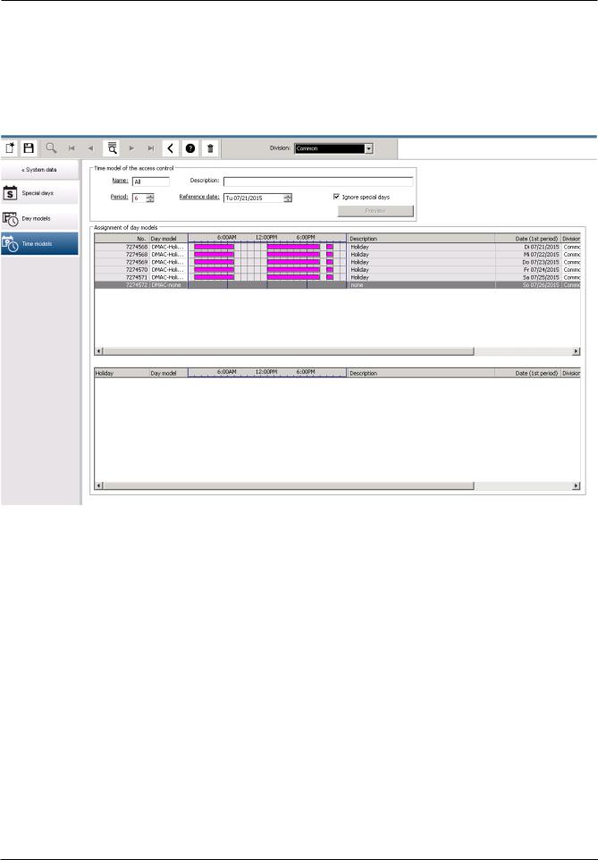
5.3Defining Time models
Existing time models can be selected from the search list and their details displayed in the dialog fields. Any processing is carried out in line with the procedure for creating new time models.
Bosch Security Systems |
Software manual |
2021-03 | 3.0.1.1 | |

16 en | Configuring the calendar |
Access Management System |
|
|
If the mask is empty, time models can be created from scratch. To do this, you must enter a name and the number of days in the period and select a starting or reference date. When this data is confirmed (Enter), a list appears in the Assignment of day models dialog field below it. The number of lines in this list corresponds to the number of days set above, and the columns already contain a progressive number and the dates for the period, beginning with the start date selected.
Only entries of the column "Name" can be changed or inserted by the user in this list - as already mentioned, the entries in the columns “No” and “Date” arise from the declarations of the dialog head; the column "Description" is filled out by the system with the choice of a day model and the explanations done in this dialog.
By double-clicking in the relevant line of the Day model column, a selection list field is activated. One of the existing day models can be selected from this list. In this way, a specific day model can be assigned to each day of the period. When the user switches to another line, an existing description of the selected day model is indicated by the system in the Description column.
The predefined holidays with the relevant day models are shown in the lower list field for navigation and checking purposes. For the selected or newly created time model, the assignment of day models to certain holidays can be changed. However, these changes will only apply to this particular time model - general changeovers that are to apply to all existing and future models can only be performed in the Holidays dialog. In line with these settings, the week days are then given the assigned day models, in consideration of the holidays. Then appropriately to these settings the weekdays are faced with the assigned day models
under consideration of the special days. To quickly check that day models are have been used and assigned correctly - particularly on holidays - this dialogue contains a preview that shows the day allocation of certain periods.
Finally, a separate dialog box is opened by clicking the Preview button and a time period of up to 90 days can be specified, including holidays. When the Calculate button is clicked, the report is composed and displayed as shown below - this process can take a few seconds depending on the size of the interval.
2021-03 | 3.0.1.1 | |
Software manual |
Bosch Security Systems |
Access Management System |
Configuring the calendar | en 17 |
|
|
In the default setting the special days are applied to the time models according to their definitions. Should the special days find, however, exceptionally no consideration, this can be caused by the choice of the option Ignore special days. Simultaneously the entries from the two lower lists are deleted, so that it is evident to the user immediately that the special days and day classes find no use in this model.
Bosch Security Systems |
Software manual |
2021-03 | 3.0.1.1 | |

18 en | Configuring Divisions Access Management System
6 Configuring Divisions
Introduction
The system may be licensed optionally to provide joint access control for a facility which is shared by any number of independent parties, called Divisions.
System operators can have one or more divisions assigned to them. Operators then see only the persons, devices and entrances of those divisions.
Where the Divisions feature is not licensed, all objects managed by the system belong to a single division called Common.
Prerequisites
–The Divisions feature is licensed for your installation.
Dialog path
– Main menu > Configuration > Divisions
Procedure
1.Click  in the tool bar.
– A new Division is created with a default name.
2.Overwrite the default name and (optional) enter a description for the benefit of other operators.
3.Click in the Color column to assign a color to help distinguish the division’s assets in the user interface.
4.Click  to save
6.1Assigning Divisions to devices
Assign Divisions to devices in the Device editor
Dialog path
Main menu > Configuration > Device data
2021-03 | 3.0.1.1 | |
Software manual |
Bosch Security Systems |

Access Management System |
Configuring Divisions | en 19 |
|
|
Prerequisites
–Divisions are licensed and in operation
–At least one division has been created.
Procedure
1.In the Device tree, select the device for assignment.
–The device editor appears in the main dialog pane.
2.From the Division list, select the new division for the device
–The list box reflects the new division.
3.Click  (Save) to save
Notice!
All components of an entrance must belong to one division
The system will not allow you to save an entrance until all its components belong to the same division.
6.2Assigning Divisions to operators
Assign Divisions to operators in the User rights dialog
Dialog path
Main menu > Configuration > Operators and workstations > User rights
Prerequisites
–Divisions are licensed and in operation
–At least one division has been created.
–At least one operator has been created in the system
Procedure
1.In the User rights dialog, select the personnel record of the operator to be assigned.
2.On the Divisions tab, use the arrow keys to move divisions from the list of Available divisions to the list of Assigned divisions for this operator.
3.Click  (Save) to save
Bosch Security Systems |
Software manual |
2021-03 | 3.0.1.1 | |

20 en | Configuring the IP addresses Access Management System
7 Configuring the IP addresses
The local access controllers on the network require a consistent scheme of IP addresses in order to participate in the access control system. The AccessIPConfig tool locates the controllers on the network and provides a convenient interface to administer their addresses and other network options centrally.
Prerequisites
–The local access controllers are powered on and connected to the network.
–You have a scheme for the IP addresses of the controllers, and their passwords if required.
Dialog path
Main menu > Configuration > Tools
Procedure
1.Follow the dialog path above and click Configuration AMC and fingerprint devices The AccessIPConfig tool opens.
2.Click Scan AMCs
The local access controllers that are available on the network are listed, each with the following parameters:
–MAC address: The hardware address of the controller. Note, this is not the address of its Main Access Controller , which is called MAC only by coincidence.
–Stored IP address:
–Port number: The default is 10001
–DHCP: The value is Yes only if the controller is configured to receive an IP address from DHCP
–Current IP addresss
–Serial number
–Notes added by the network configuration team
3.Double-click an AMC in the list to change its parameters in a popup window. Alternatively, select the line of the desired AMC and click Set IP… Note that it may be necessary to enter a password, if one has been configured for the device.
The modified parameters are stored as soon as you click OK in the popup window.
4.When you have finished configuring the IP parameters of the controllers, click File > Exit to close the tool.
You will return to the main application.
For more detailed information, click Help in the AccessIPConfig tool to view its own help file.
2021-03 | 3.0.1.1 | |
Software manual |
Bosch Security Systems |
Access Management System Using the Device Editor | en 21
8 Using the Device Editor
Introduction
The Device Editor is a tool for adding, deleting or modifying entrances and devices.
The Device Editor offers views for the following editable hierarchies:
–Device configuration: the electronic devices within the access control system.
–Workstations: the computers cooperating in the access control system.
–Areas: the physical areas into which the access control system is divided.
Prerequisites
The system is correctly installed, licensed and on the network.
Dialog path
–Main menu >Configuration > Device data
Using the Device Editor toolbar
The Device Editor toolbar offers the following functions, regardless of which view is active:
Devices, Workstations or Areas.
Button |
Shortcut |
Description |
|
|
|
|
Ctrl + N |
Creates a new item below the selected node. |
|
|
Alternatively, right-click the node to invoke its context menu. |
|
|
|
|
Del |
Deletes the selected item and all beneath it. |
|
|
|
|
Ctrl-Page up |
First item in the tree |
|
|
|
|
Ctrl - |
Previous item |
|
|
|
|
Ctrl + |
Next item |
|
|
|
|
Ctrl-Page |
Last item in the tree |
|
down |
|
|
|
|
|
Ctrl-A |
Expands and collapses the tree. |
|
|
|
|
Ctrl-K |
Refreshes the data by reloading them from the database. |
|
|
All unsaved changes are discarded. |
|
Ctrl-S |
Saves the current configuration |
|
|
|
|
Ctrl-F |
Opens a search window |
|
|
|
|
|
Open the Device configuration tree |
|
|
|
Bosch Security Systems |
Software manual |
2021-03 | 3.0.1.1 | |

22 en | Using the Device Editor |
Access Management System |
|
|
Open the Workstations tree
Open the Areas tree
In all Device Editor views, start at the root of the tree and add items using the toolbar buttons, the menu or the context menu of each item (right-click to invoke it). To add sub-items to a device, first select the parent device under which the sub-items should appear.
Copying and pasting AMC devices
To copy AMC devices from one part of the tree to another:
1.Right-click the AMC device and select Copy from the context menu.
2.Right-click on a suitable parent device elsewhere in the tree, and select Paste from the context menu.
–The device is copied to the new location with its sub-devices and settings.
–Device parameters such as IP address and Name, which must be unique, are not copied.
3.Enter unique values for those device parameters that require them. Until you do this you cannot save the device tree.
Saving your work
When you have finished adding and modifying items in the tree, click Save  to save the configuration.
To close the Device Editor, click File > Exit.
2021-03 | 3.0.1.1 | |
Software manual |
Bosch Security Systems |

Access Management System Configuring areas of access control | en 23
9 Configuring areas of access control
Introduction to Areas
Secured facilities can be divided into Areas. Areas can be of any size: one or several buildings, single floors or even single rooms.
Some uses of Areas are:
–The localization of individual persons within the secured facilities.
–The estimation of the number of persons within a given area, in case of an evacuation or other emergency.
–Limiting the number of persons or vehicles in an area:
When the predefined population limit is reached, further admissions can be rejected until persons or vehicles leave the area.
–Implementing access sequence control and anti-passback
The system distinguishes between two types of access-controlled areas
–Areas for persons
–Areas for vehicles (parking lots)
Each area may have sub-areas for finer granularity of control. Areas for persons may have up to 3 levels of nesting, and areas for parking lots only 2, namely the overall parking lot and parking zones, between 1 and 24 in number.
The default area, which exists in all installations, is called Outside. It serves as the parent for all user-defined areas of both kinds: person and parking lots.
An area is not usable unless at least one entrance leads into it.
Device Editor DevEdit can be used to assign a location area and a destination area to any entrance. When someone scans a card at a reader belonging to an entrance, the person’s new location becomes the destination area of that entrance.
Notice!
Access sequence control and anti-passback require both entrance and exit readers at the areas' entrances.
Turnstile-type entrances are strongly recommended to prevent accidental or deliberate “tailgating "
Procedure for creating areas Prerequisites
As a system operator you require an authorization from your system administrator to create areas.
Dialog path (AMS)
1.In the AMS dialog manager select Main menu > Configuration > Device data
2.Click Areas 
3.Select the node Outside, or one of its children, and click  in the toolbar. Alternatively, right-click Outside to add an area via its context menu.
All areas created initially receive a unique name of Area plus a numeric suffix.
Bosch Security Systems |
Software manual |
2021-03 | 3.0.1.1 | |
24 en | Configuring areas of access control |
Access Management System |
|
|
4.In the popup window select its type, that is Area for persons or Parking lot for vehicles. Note that only Outside can have children of both types. Any sub-area of these children always inherits the type of its parent.
–Areas for persons can be nested to three levels. For each area or sub area you can define a maximum population.
–Parking lots are virtual entities consisting of at least one parking zone. If the population of a parking lot does not need to be limited by the system, 0 is displayed. Otherwise the maximum number of parking spaces per zone is 9999, and the parking lot main pane displays the sum of all the spaces in its zones.
Procedure for editing areas
1.Click an Area in the hierarchy to select it.
2.Overwrite one or more of the following attributes in the main pane of the dialog.
Name |
The default name, which you may overwrite. |
Description |
A free-text description of the area. |
Maximum number of |
Default value 0 (zero) for no-limit. |
persons / cars |
Else, enter an integer for its maximum population. |
Notes:
–An area cannot be moved by dragging and dropping to a different branch of the hierarchy. If necessary, delete the area and recreate it on another branch.
Procedure for deleting areas.
1.Click an area in the hierarchy to select it.
2.Click Delete  or right-click to delete via the context menu. Note: an area cannot be deleted until all its children have been deleted.
9.1Configuring areas for vehicles
Creating areas for vehicles (parking lot, parking zone)
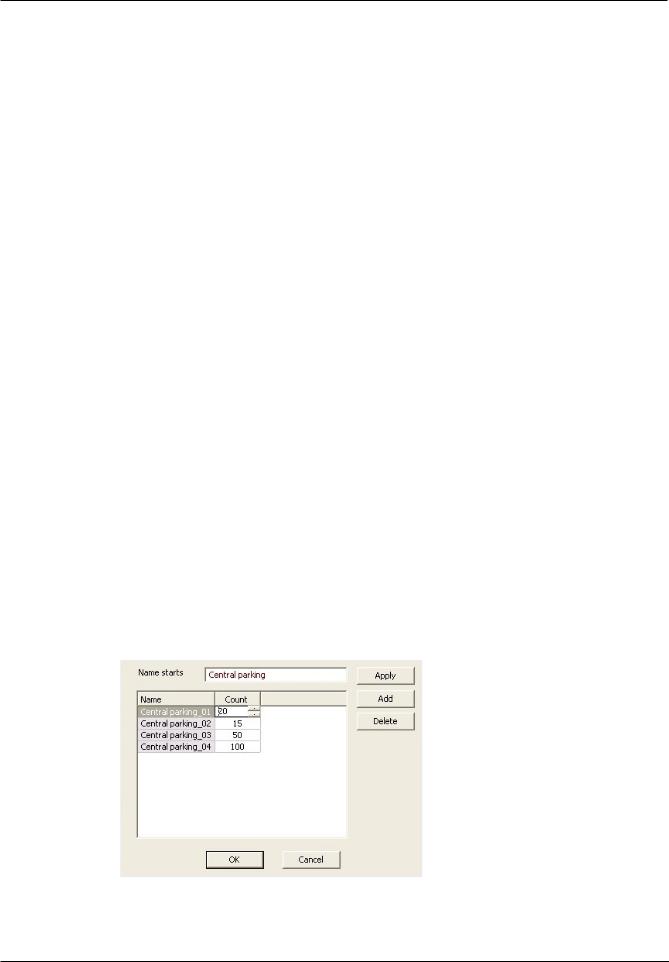
If you select an area type of Parking lot a popup window appears.
1.Enter a name in the field Name starts with to create a trunk name for all its parking subareas or parking zones.
Up to 24 parking zones can be created using the Add button, and each will have the trunk name plus a 2-digit suffix.
2021-03 | 3.0.1.1 | |
Software manual |
Bosch Security Systems |

Access Management System |
Configuring areas of access control | en 25 |
|
|
2.If the system is to limit the population of these areas, enter the number of parking spaces
in the Count column. If no population limit is required, enter 0.
Note: The maximum population of the entire parking lot is the sum of these numbers. Only parking zones can contain parking spaces; the parking lot is only a virtual entity consisting of at least one parking zone. The maximum number of parking spaces per zone is 9999.
Creating entrances for parking lots
As with normal areas, parking lots require an entrance. The appropriate door model is
Parking lot 05c.
For monitoring the population of a parking lot 2 entrances with this door model are required on the same AMC, one for ingress and one for egress.
Prerequisite
Create a parking lot with at least one parking zone, as described above.
Dialog path
Main menu > Configuration > Device data
Click LACs/Entrances/Devices 
Procedure
1.In the device hierarchy, create an AMC, or select an AMC that has no dependent entrances.
2.Right-click the AMC and select New entrance
3.In the New entrance popup window select Entrance model Parking lot 05c and add an inbound reader of the type installed at the parking lot entrance.
4.Click OK to close the popup window.
5.Select this newly created entrance in the device hierarchy.
–Note that the system has automatically designated the reader as an Entry reader.
6.In the main editing pane, on tab Parking lot 05c, select from the Destination pull-down menu the parking lot that you created previously.
7.Right-click the AMC again, and create another entrance of type Parking lot 05c as above.
–Note that this time you can only select an outbound reader.
–Click OK to close the popup window.
8.Select this second newly created entrance in the device hierarchy
–Note that the system has automatically designated the second reader as an Exit reader.
Bosch Security Systems |
Software manual |
2021-03 | 3.0.1.1 | |

26 en | Configuring intrusion areas and panels Access Management System
10 Configuring intrusion areas and panels
Introduction
The access control system supports the administration and operation of Bosch intrusion panels. Consult the datasheet of the access control system for details of the models that it supports. The access control system adds particular value in the administration of the intrusion panel users. These users are a subset of the cardholders of the overall access control system. Access control system administrators give these cardholders special authorizations to administer and operate the intrusion panels through the AMS Dialog Manager.
The intrusion panels themselves are configured and updated as previously through their Remote Programming Software (RPS). AMS continually reads from the RPS database, and displays the panels that are in it.
AMS contains dialogs to create panel users and their authorization profiles, and to manage the panels.
Prerequisites
–The RPS of supported Bosch intrusion panels is installed on a separate computer in the AMS system, not on the AMS server. Consult the RPS installation guide for installation instructions.
–RPS has been configured with the intrusion panels that will belong to the AMS access control system. Consult the RPS user guide or online help for instructions.
–The clocks on the panels are within 100 days of the clock on the AMS server, to enable automatic synchronization.
–Mode 2 protocol is set on all participating panels.
–Cards with one of the following standard card definitions:
–HID 37 BIT -> Intrusion 37 BIT with a facility/site code of 32767 or lower.
–HID 26 BIT- > Intrusion 26 BIT
–EM 26 BIT- > Intrusion 26 BIT
Overview
The configuration process consists of the following stages, described in the following sections in this chapter:
1.Connecting the access control system to the intrusion panels.
–Connecting to the RPS API.
–Configuring the panel connections.
2.Creating panel authorization profiles that govern which functions of the connected panels can be used.
3.Assigning panel authorization profiles to cardholders.
–These cardholders thus become operators for the intrusion panels.
10.1Connecting the access control system to the intrusion panels
Introduction
This section describes how to view the intrusion panels and make them available for control through Map View. The access control system connects to one RPS on its network, and through it maintains an up-to-date internal list of the compatible intrusion panels that are available.
Dialog path
Main menu > Configuration > Panels and subdialogs
2021-03 | 3.0.1.1 | |
Software manual |
Bosch Security Systems |

Access Management System |
Configuring intrusion areas and panels | en 27 |
|
|
10.1.1Step 1: Connecting to the RPS API
The RPS API is an interface to the RPS, which is running on a separate computer. Step 1 is to provide the computer's address and administrator login information to the access control system.
Dialog path
Main menu > Configuration > Panels > RPS API configuration
Procedure
1.Enter the following information:
Information |
Description |
Host name / IP address |
The HTTPS address of the computer on which the RPS is |
|
running, and the port number through which the RPS |
|
communicates. |
|
The default port number is 9000. |
|
|
User name |
The user name of an RPS administrator user for the API. |
|
|
Password |
The password of the RPS administrator user. |
|
|
2.Click the button Test the connection to ensure that the RPS is running, and that the user name and password are valid
10.1.2Step 2: Configuring the panel connections
Step 2 is to define the amount of control that the access control system has over individual panels on the network.
Dialog path
Main menu > Configuration > Panels > Panel administration
The dialog maintains a list of the compatible intrusion panels that the RPS API has provided to the AMS.
The list is periodically updated in the background. After you open the dialog, click  occasionally, to force an immediate update manually.
The list is read-only, except for the controls described in the following section.
Procedure
Use the controls below to allow control of individual intrusion panels by the access control system.
List column |
Select the check box to ensure that the users of the intrusion |
User administration |
panel in this row are maintained in the access control system and |
|
not on the panel itself. |
|
IMPORTANT: this setting causes all panel users that were created |
|
locally in RPS to be overwritten. |
|
|
List column Map View |
Select the check box to make this panel available for Command |
|
and Control through the Map View . |
Bosch Security Systems |
Software manual |
2021-03 | 3.0.1.1 | |

28 en | Configuring intrusion areas and panels Access Management System
|
|
If you selected the check box in the Map View column, click the |
|
Settings |
(cog) |
icon to enter a host name or IP address, a port and the passcode |
|
for the individual panel. |
|||
icon in the Access data |
|||
|
|||
column. |
|
|
|
|
|
|
|
Button: |
|
If a panel has been deleted in RPS it appears with a status of |
|
Delete selected panel |
Removed in the list. Select the panel and click this button to |
||
|
|
delete it completely from the database. |
|
|
|
|
|
10.2Creating authorization profiles for panels
Introduction
This section describes how to create panel authorization profiles.
A panel authorization profile is a custom set of authorizations to operate a custom set of intrusion panels. An AMSadministrator can create multiple panel authorization profiles for the various responsibilities of various groups of cardholders.
Dialog path
Main menu > System data > Authorization profiles for intrusion panels
Procedure
1.Click  to create a new profile
2.(Mandatory) Enter a name for the profile
3.(Optional) Enter a free-text description for the panel
4.Below the Assigned panels list, click Add… to add one or more panels from a popup list of panels available on the network.
Conversely, select one or more panels and click Remove to remove them from the list.
5.Click a panel in the Assigned panels list to select it.
–In the Authorizations pane, a list appears containing all the intrusion areas that belong to the selected panel.
6.In the Authorizations list, in the column Authority level, select an authority level for each intrusion area of the panel that is to be included in this profile.
–The authority levels are defined and maintained in RPS. They may be customized there also. Make sure you know the definition of the authority level in RPS before assigning it to a profile.
–By default L1 is the highest authority level, with L2, L3 etc. increasingly restricted.
–If you leave a cell blank, then the recipient of this profile will have no authorization over the selected intrusion area of the selected panel.
7.Repeat this process for all the intrusion areas of all the panels to be included in this profile.
8.(Optional) From the User group list, select a panel user group in order to restrict the authorizations to certain time periods.
–The user groups are defined and maintained in RPS. They may be customized there also. Make sure you know the definition of the user group in RPS before assigning the user group to a profile.
9.Click  (Save) to save the changes.
2021-03 | 3.0.1.1 | |
Software manual |
Bosch Security Systems |

Access Management System |
Configuring intrusion areas and panels | en 29 |
|
|
10.3Assigning panel authorization profiles to cardholders
Introduction
This section describes how to assign different panel authorization profiles to different types or groups of cardholders.
Prerequisite
You have defined one or more panel authorization profiles in the access control system.
Dialog path
Main menu > Persons > Cards
Procedure
1.In the usual way, find and select the desired cardholder from the database.
2.Click the Intrusion tab.
3.On the Intrusion tab, select the check box Panel user.
4.(Mandatory) In the Passcode field, type a passcode through which this cardholder will operate the intrusion panels.
–If required, use the button to generate an unused new passcode.
5.In the ID card list, select one of the access control credentials that is assigned to this cardholder.
6.(Optional) In the Number of remote field, enter the number that is printed on the cardholder's remote control device for intrusion panels.
7.In the Language list, select the language in which the cardholder prefers to read panel dialogs.
8.If the cardholder is to use the Bosch smartphone application for intrusion panels, select the Remote access check box.
9.From the Authorization profile list, select a suitable panel authorization profile for the cardholder.
10.Click  (Save) to save the changes.
–This panel authorization profile, with all its panels and authorizations, is assigned to the cardholder. The cardholder thus becomes an operator for the intrusion panels.
Note that you can also use the data fields on this dialog with the  button to find cardholders in the database.
Bosch Security Systems |
Software manual |
2021-03 | 3.0.1.1 | |

30 en | Configuring operators and workstations Access Management System
11 Configuring operators and workstations
Introduction to access-control administration rights
Administration rights for the access control system determine which system dialogs may be opened, and which functions may be performed there.
Rights can be assigned to both operators and workstations.
The rights of a workstation may temporarily restrict the rights of its operator, because security-critical operations should only be performed from workstations that are especially secure.
Rights are assigned to operators and workstations in bundles called Profiles. Each profile is tailored to the duties of one of a particular type of operator or workstation.
Each operator or workstation may have multiple authorization profiles.
Overall procedure and dialog paths
1.Create the workstations in the Device Editor:
Configuration > Device data > Workstations 
2.Create workstation profiles in the dialog:
Operators and workstations > Workstation profiles.
3.Assign profiles to workstations in the dialog:
Operators and workstations > Workstation rights
4.Create operator profiles in the dialog:
Operators and workstations > User profiles dialog.
5.Assign profiles to operators in the dialog:
Operators and workstations > User rights dialog
11.1Creating the workstations
Workstations are the computers from which operators operate the access control system. First a workstation must be “created”, that is, the computer is registered within the access control system.
Dialog path
Configuration > Device data > Workstations
Procedure
1.Right-click DMS and select New object from the context menu, or click  on the toolbar.
2.Enter values for the parameters:
–The Name of the workstation must match the computer name exactly
–Description is optional. It can be used, for example, to describe the function and the location of the workstation
–Login via reader Leave this check box clear unless operators are to log on to this workstation by presenting cards to an enrollment reader connected to this workstation. For details see the section 2-Factor Authentication
–Automatic logout after: The number of seconds after a logon via enrollment reader is automatically terminated. Leave at 0 for unlimited time.
2021-03 | 3.0.1.1 | |
Software manual |
Bosch Security Systems |
Loading...