


P4M890-M7 TE

P 4M 900-M7 S E / P4M 890-M7 TE
Setup Manual
FCC Inf or m at ion and Copyri ght
This equipment has been tested and found to comply with the limits of a Class
B digital device, pursuant to Part 15 of the FCC Rules. T hese limits are designed
to p rovid e reasonable protection against harmful interfe rence in a res idential
installation. This equipment generates, uses, and c an radiate radio frequency
energy and, if not installed and used in accordance with the instructions, may
cause harmful interference to radio communications. There is no guarantee
that interfe rence will not oc cur in a particular ins tallatio n.
The vendo r makes no repres entations o r warra nties with respec t to the
contents here and specially disclaims any implied warranties of merchantability
o r fi tness fo r a ny p u rp ose . Furthe r the ve ndo r res e rves the ri g ht to rev is e this
publication and to make c hanges to the c ontents here without obligation to
notify any party beforehand.
D uplica tion o f this publicat ion, in p art o r in wh ole, is not al lowed without first
obtaining the vendor’s approval in writing.
The content of this user’s manual is subject to be changed without notice and
we will not be respo nsible for any mistakes found in this user’s manual. All the
brand and product names are trademarks of their respec tive companies.

Table of Contents
Chapt er 1: Introdu ct ion .............................................3
1.1 Before You Start................................................................... 3
1.2 Package Checklist................................................................3
1.3 Motherboard Features..........................................................4
1.4 Rear Panel C onnectors..........................................................5
1.5 Mo t he r bo ar d Layou t............................................................ 6
Chapt er 2: Hardware Installation..............................7
2.1 Installing Ce ntral Proce ssing Unit (CPU) ................................ 7
2.2 Fan He ade rs.........................................................................9
2.3 Installing System Memo ry.....................................................10
2.4 Con nectors and Slo ts............................................................11
Chapt er 3: Headers & Jumpers Setup .....................13
3.1 How to Setup Jum per s..........................................................13
3.2 Det ail Settin gs.....................................................................13
Chapt er 4: RAID Functions.......................................18
4.1 Operation System................................................................18
4.2 Raid Array s.........................................................................18
4.3 How RA I D Wo r k s.................................................................18
Chapt er 5: Useful Help .............................................20
5.1 Dr i ver Insta llat ion Note.......................................................20
5.2 Award BIOS Beep Code........................................................21
5.3 Extra Informati on ................................................................21
5.4 Troubleshooting...................................................................22
Chapt er 6: WarpSpeeder™ I II .................................23
6.1 Introduction ........................................................................23
6.2 System Requirement............................................................23
6.3 Installation.........................................................................24
6.4 WarpSpeede r™ III................................................................25
Appendencies: SPEC In Other Language ................30
German................................................................................................30
France..................................................................................................32
Italian..................................................................................................34
Spanish ................................................................................................36
Portuguese ...........................................................................................38
Polish...................................................................................................40
Russian ................................................................................................42
Arabic..................................................................................................44
Japanese..............................................................................................46

CHAPTER 1: INTRODUCTION
P4M900-M7 SE/P4M890-M7 TE
1.1 B
EFORE YOU START
Tha nk you for choosing our product. Be fore you start installing the
mothe rboa rd, plea se make sure you fo llo w the instructio ns be lo w:
Prepare a dry and s table working environment with
s ufficie nt ligh ting.
Always disconnect the computer from power outlet
be fo re ope ra tion .
Befo re you take the mo the rboa rd ou t f rom a nti-s ta t ic
bag, ground yourself properly by touching any safely
grounde d appliance, or use gro unded wrist strap to
remove the static charge.
Avo id tou ch ing the compone nts o n m o the rboa rd o r the
rea r side of the board unless ne cessary. Ho ld the board
on the edge , do not try to be nd or flex the board.
Do no t lea ve an y un fas tene d small pa rts inside the
case after installation. Loose parts will cause short
circuits which ma y damage the equipment.
Keep the computer from dangerous area, such as heat
source , humid air and wate r.
1.2 PACKAGE CHECKLIST
HDD Cable X 1
I nstalla tion Guide X 1
Fully Se tup Drive r CD X 1 ( full ve rsion manual files ins ide )
Rear I/O Panel for ATX Case X 1
FDD Cable X 1 (optional)
Se ria l ATA Cab le X 1 (optiona l)
USB 2.0 Cable X1 (optional)
Se ria l ATA Po wer C able X 1 (o ptiona l)
Note: The package contents may differ by area or your motherboard version.
3
Motherboard Manual
/
p
/
p
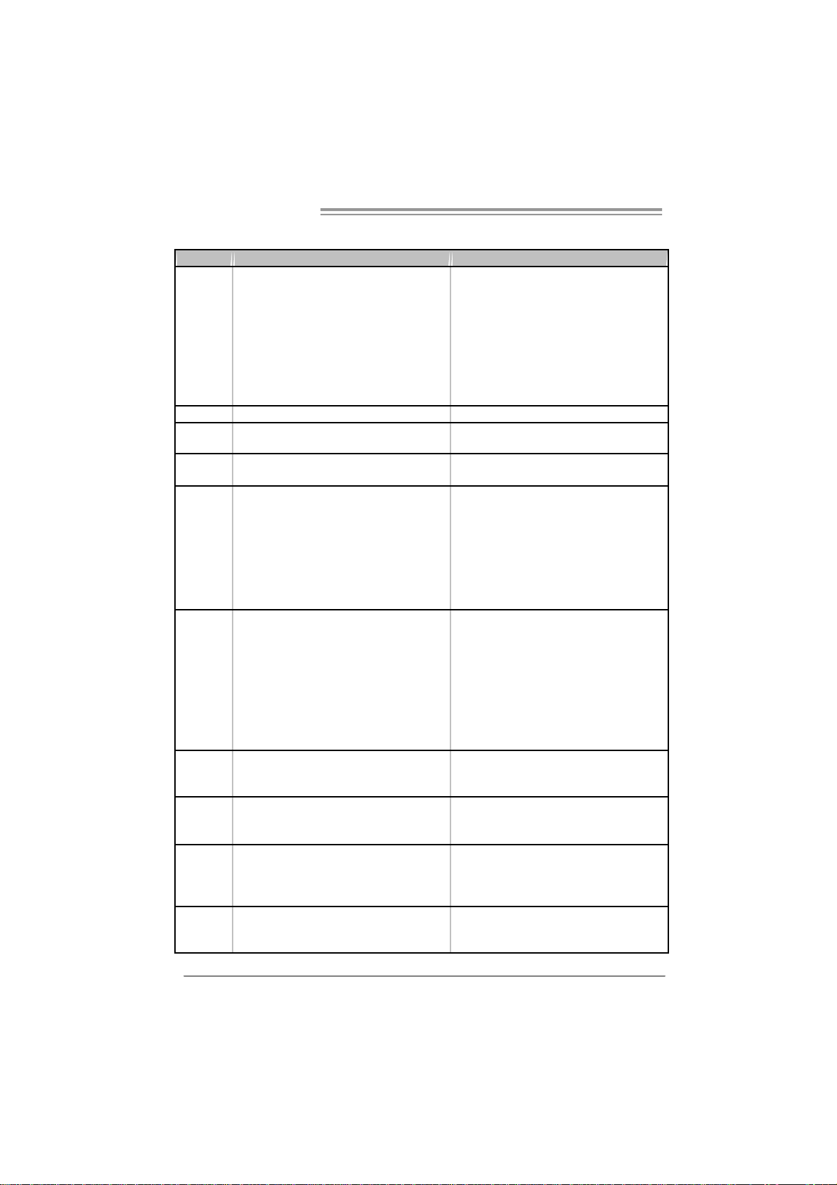
1.3 MOTHERBOARD FEATURES
P4M900-M7 SE P4M890-M7 TE
LGA 775
Intel Core2Duo/ Pentium 4 / Pentium D /
Celeron D / Celeron 4xx pr ocessor up to 3.8
GHz
CPU
FS B 533 / 800 / 106 6 MHz 533 / 800 / 106 6 MHz
Chipset
Graphic
Super I/O
Main
Memory
IDE
SATA
LAN PHY
Sound
Codec
Supports Hyper Threading
Bit / Enhanced Intel S peedStep®/ Intel
Extended Memor y 64 technology
*It is recommended to use
95W power consum pti on.
VIA P4M900
VIA VT8237A
Chr ome9 HC 3D / 2D Gr ap hic s
Max Shared Vide o Memory is 256 MB
ITE 871 2F
Provides the most commonly used legacy
Super I/O functionality.
Low Pin C ount Interf ace
Environment Control initiatives,
H/W Monitor
Fan S pee d Co ntroller
ITE' s "Smart Guardian" func tion
DIMM Slots x 2
Supports D DR2 533 / 667
Eac h DIMM supports 2 56/ 512MB/1GB/ 2GB
DDR2
Max Memory C apicity 4GB
Single Channel Mode DDR2 memory
module
Registered DIMM and ECC DIMM is not
supported
Integrated IDE Controller
Ultra DMA 33~133 Bus Master Mode
supports PIO Mo de 0~4,
Integrated Seri al ATA Controller
Data transfer rates up to 1.5 Gb/s.
SATA Version 1.0 specification compliant.
Realtek RTL 8201CL PHY/
At heros AR 8012 PHY (Optional)
10 / 100 Mb/s auto negotiation
Half / Full du plex capability
AL C662
5.1 cha nnels a udio out
High- Defi nition Au dio s upport
Execute Disable
rocessors with
LGA 775
Intel Core2Duo/ Pentium 4 / Pentium D /
Celeron D / Celeron 4xx pr ocessor up to 3.8
GHz
Supports Hyper Threading
Bit / Enhanced Intel S peedStep®/ Intel
Extended Memor y 64 technology
*It is recommended to use
95W power consum pti on.
VIA P4M890
VIA VT8237A
Unichrome Pr o IGP
Max Shared Vide o Memory is 64 MB
ITE 871 2F
Provides the most commonly used legacy
Super I/O functionality.
Low Pin C ount Interf ace
Environment Control initiatives,
H/W Monitor
Fan S pee d Co ntroller
ITE' s "Smart Guardian" func tion
DIMM Slots x 2
Suppor ts DDR2 533
Eac h DIMM supports 2 56/ 512MB/1GB/ 2GB
DDR2
Max Memory C apicity 4GB
Single Channel Mode DDR2 memory
module
Registered DIMM and ECC DIMM is not
supported
Integrated IDE Controller
Ultra DMA 33~133 Bus Master Mode
supports PIO Mo de 0~4,
Integrated Seri al ATA Controller
Data transfer rates up to 1.5 Gb/s.
SATA Version 1.0 specification compliant.
Realtek RTL 8201CL PHY/
At heros AR 8012 PHY (Optional)
10 / 100 Mb/s auto negotiation
Half / Full du plex capability
AL C662
5.1 cha nnels a udio out
High- Defi nition Au dio s upport
Execute Disable
rocessors with
4
P4M900-M7 SE/P4M890-M7 TE
g
g
P4M900-M7 SE P4M890-M7 TE
PCI Express x 16 slot x1 PCI Express x 16 slot x1
PCI Express x 1 slot x1 PCI Express x 1 slot x1 Slots
PCI s lot x2 PCI slot x2
Floppy connector x1 Floppy connector x1
Printer Port Conn ector x1 Printer Port Connector x1
IDE C onnector x2 IDE C o nnector x2
SATA Connector x2 SATA Connector x2
Front Pa nel C o nnector x1 Front Pa nel C onnector x1
On Board
Connector
Back Panel
I/O
Board S iz e 190 mm (W) x 244 mm (L) 190 mm (W) x 244 mm (L)
Special
Feature
OS
Suppor t
Front Audi o Co nnector x1 Front A udio Connect or x1
CD-in Co nnector x1 CD-in Connect or x1
CPU Fan header x1 CPU Fan hea der x1
Syst em Fan hea der x1 Syst em Fan hea der x1
Clear CMOS header x1 Clear CMOS header x1
USB connector x2 USB connector x2
Power Connector (24pi n) x1 Power Connector (24pi n) x1
Power Connector (4pin) x1 Power Connector (4pin) x1
PS/2 Keyb oard x1
PS/2 Mo use x1
Serial Port x1
VGA Port x1
LAN port x1
USB Port x4
Audio Jack x3
RAID 0 / 1 support RAID 0 / 1 support
Windows 2000 / XP / VISTA
Biostar Reserves the ri
support for any OS with or witho ut notice.
ht t o add or r emo ve
PS/2 Keyb oard x1
PS/2 Mo use x1
Serial Port x1
VGA Port x1
LAN port x1
USB Port x4
Audio Jack x3
Windows 2000 / XP
Biostar Reserves the ri
support for any OS with or witho ut notice.
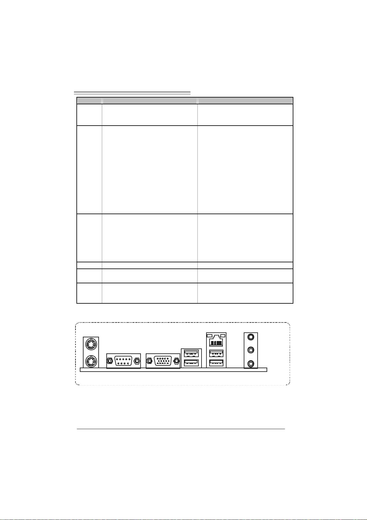
1.4 REAR PANEL CONNECTORS
PS/2
Mouse
LA N
ht t o add or r emove
Li ne I n /
Surround
Line O ut
Mic In 1/
Bass/ Center
PS/2
Keyboard
COM1 VGA
USBX2USBX2
Since t he audi o c hip s uppor ts Hig h Definiti on Audi o Speci fic ati on, the func tion of eac h audi o
jack c an be defi ne d by sof twar e. T he in put / output func tion o f eac h audi o jac k l is ted above
represents t he default s etti ng . Ho we ver , wh en c onnec ti ng e xter nal micr ophon e to t he audi o
port, pleas e us e t he Lin e In ( blu e) an d Mi c In (Pi nk) audio j ac k.
5
Motherboard Manual
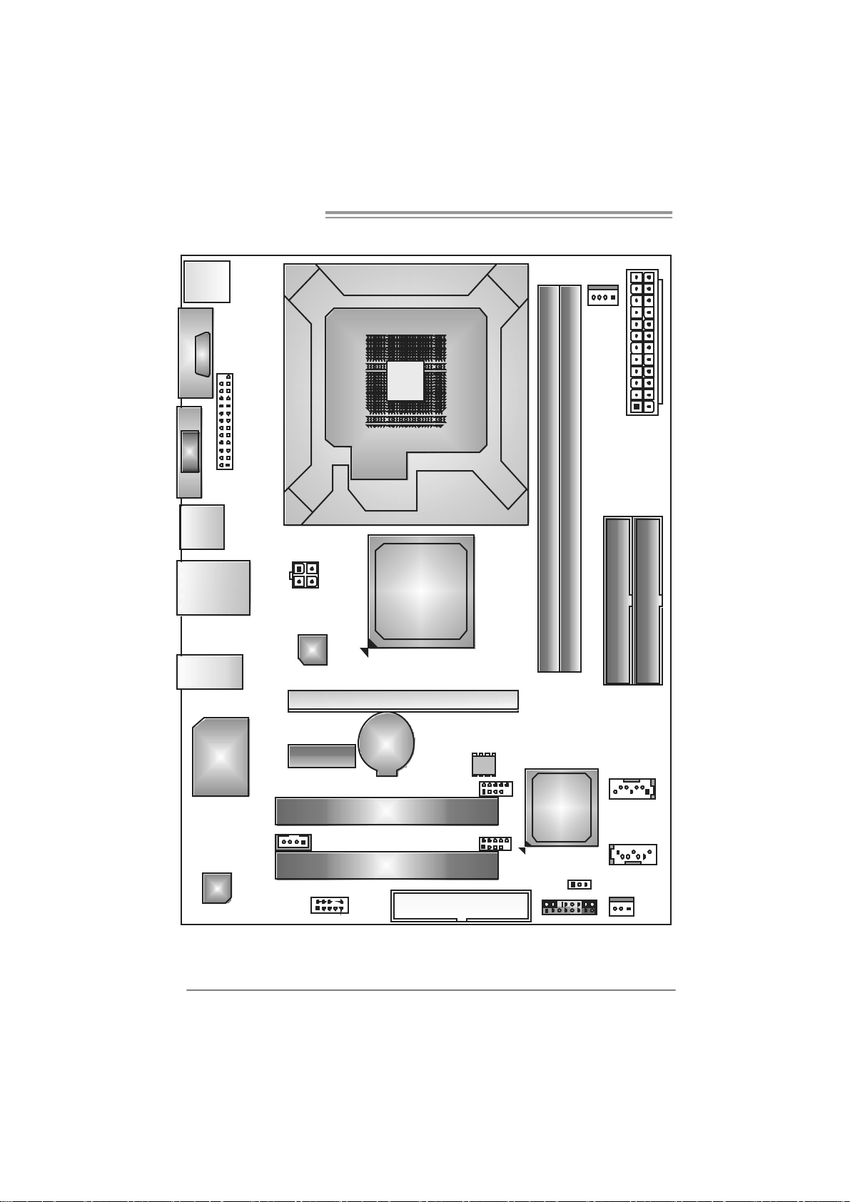
1.5 MOTHERBOARD LAYOUT
JKBMS1
C
O
J
M
C
1
O
M
1
JVGA1
JPRNT1
JU SB1
JUSBLAN1
JAUDIO1
JATXPWR2
LAN
LGA775
CPU 1
P4M900
or
P4M890
DIMM1
DIMM2
JCFAN1
JATXPWR1
IDE1
IDE2
6
Super
I/O
JCDIN1
Codec
Note: represents the 1■
JA UDIO F1
PCI -EX1 _1
PCI -E X16
BAT1
PCI1
PCI2
st
pin.
JU SB 2
JUSB3
FDD1
BI OS
VIA
VT8237A
JCMOS1
J P AN EL 1
JSATA2
JSATA1
JSFAN1
P4M900-M7 SE/P4M890-M7 TE
CHAPTER 2: HARDW ARE INSTALLATION
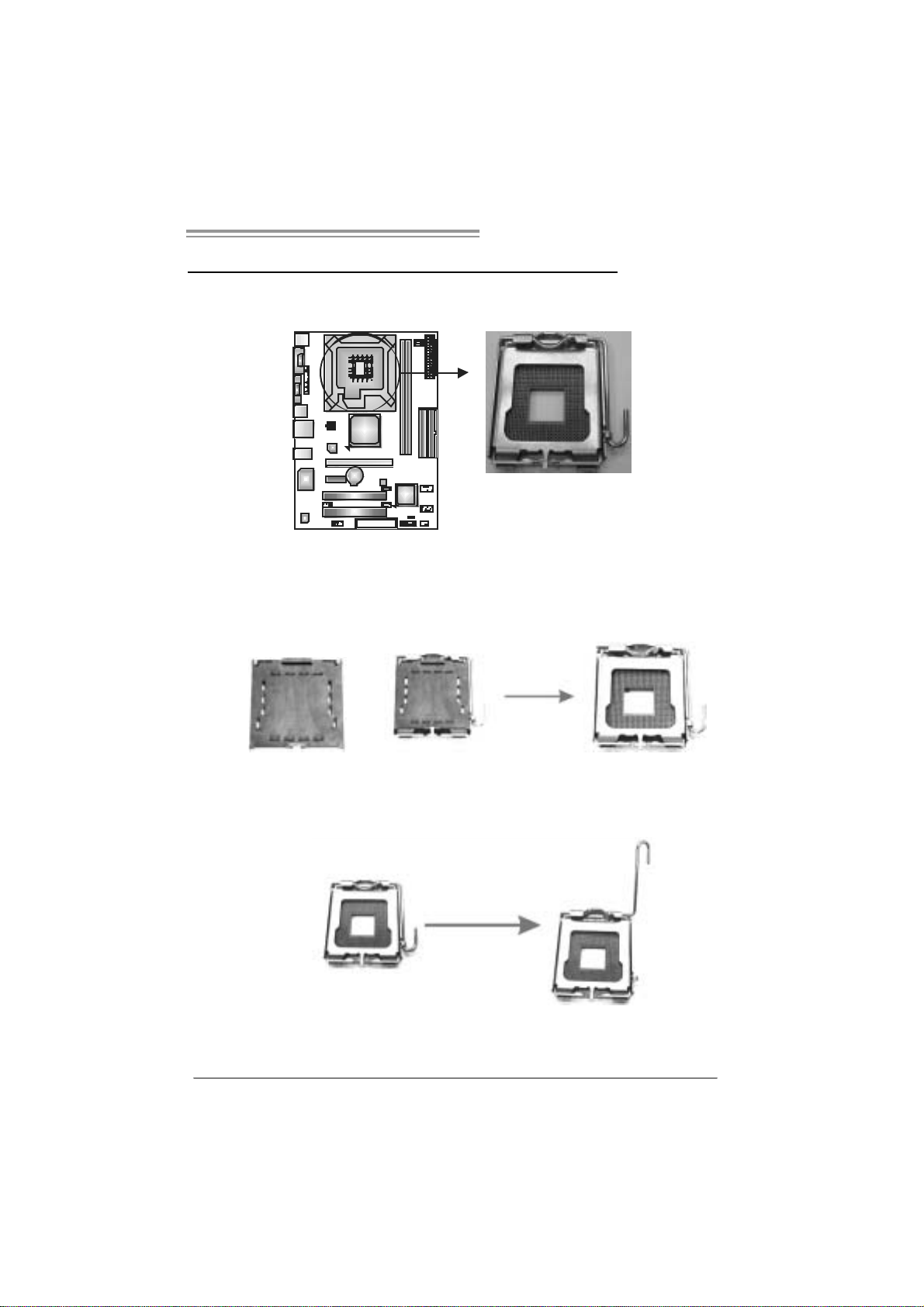
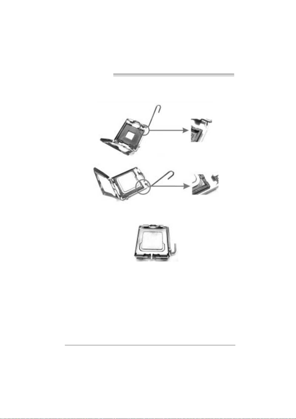
2.1 INSTALLI NG CENTRAL PROCESSI NG UNIT (CPU)
Special Notice:
Remo v e Pin Cap before installation, and ma ke goo d preservation
for future use. When the CPU is remo ved, cov er the Pin Cap on the
empty so cket to ensure pin legs won’ t be damag ed.
Pin Cap
Step 1: Pull the socket locking lever out from the socket and then raise
the lever up to a 90-degree angle.
7
Motherboard Manual
Step 2: Look for the triangular cut edge on socket, and the golden dot on
CPU should point forwards this triangular cut edge. The CPU will
fit only in the correct orientation.
Step 2-1:
Step 2-2:
Step 3: Hold the CPU down firmly, and then lower the lever to locked
position to complete the installation.
Step 4: Put the CPU Fan and heatsink assembly on the CPU and buckle it
on the retention frame. Connect the CPU FAN power cable into
the JCFAN1. This completes the installation.
8
P4M900-M7 SE/P4M890-M7 TE
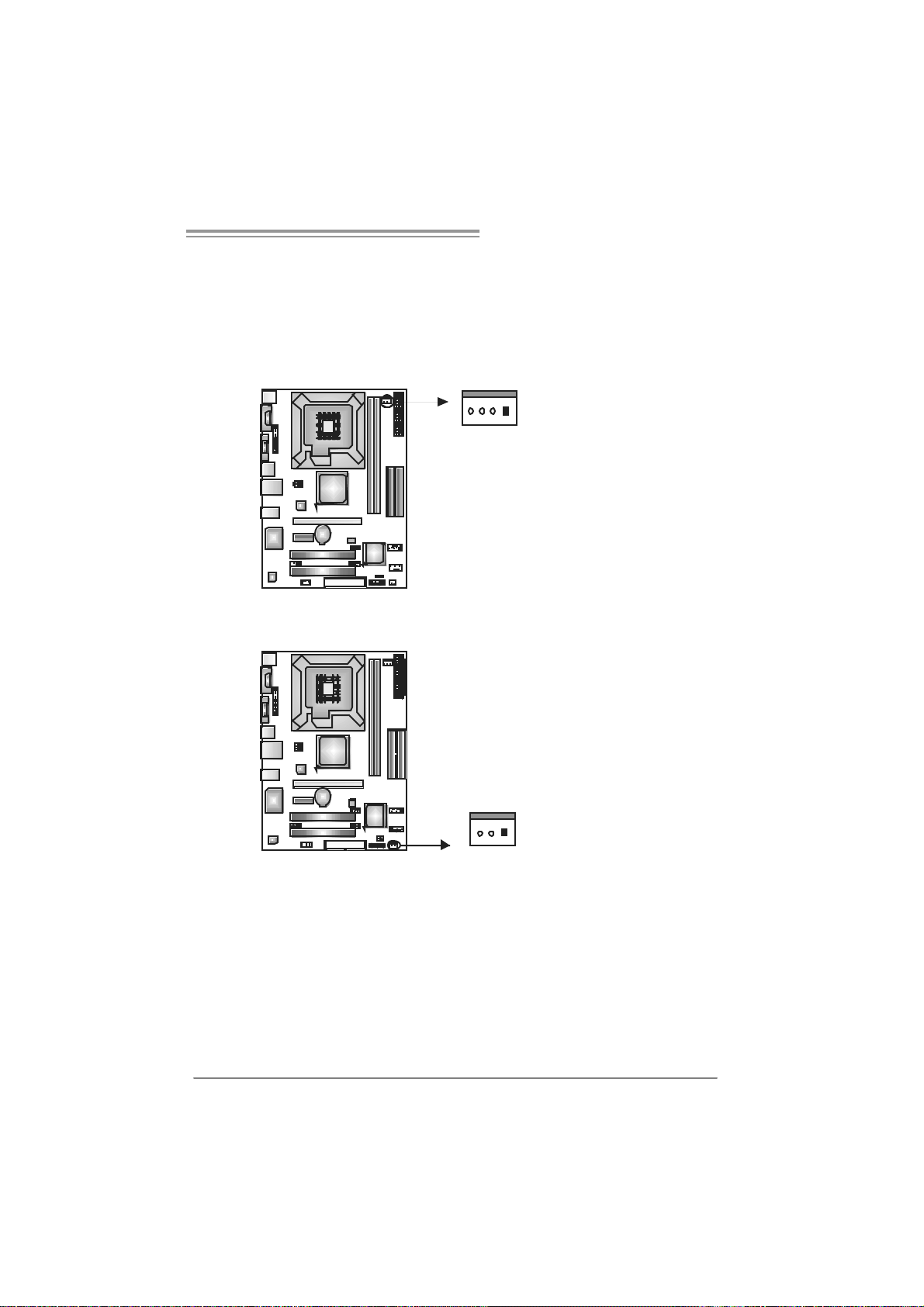
2.2 FAN HEADERS
These fan headers support cooling-fans built in the computer. The fan
cable and connector may be different according to the fan manufacturer.
Connect the fan cable to the connector while matching the black wire to
pin#1.
JCFAN1: CPU Fa n Header
Pin
14
JSF AN1 : Sy stem F an H eader
Assignment
1 Ground
2 +12V
3 FAN RPM rate
sense
4 Smart Fan
Control
Pin
Assignment
1 Ground
2 +12V
3 FAN RPM rate
sense
13
Note:
The J SFAN1 supports 3-pin head c onnect or a nd the JCFAN1 su pports 4-pin head
conn ector . Wh en connecti ng with wires on to c onnec t ors, pl ease n ote th at t he r ed wire i s
the positi ve and s ho uld be c onnect ed to pi n#2, an d th e blac k wire i s Groun d and s ho uld
be c onnect ed t o GND .
9
Motherboard Manual
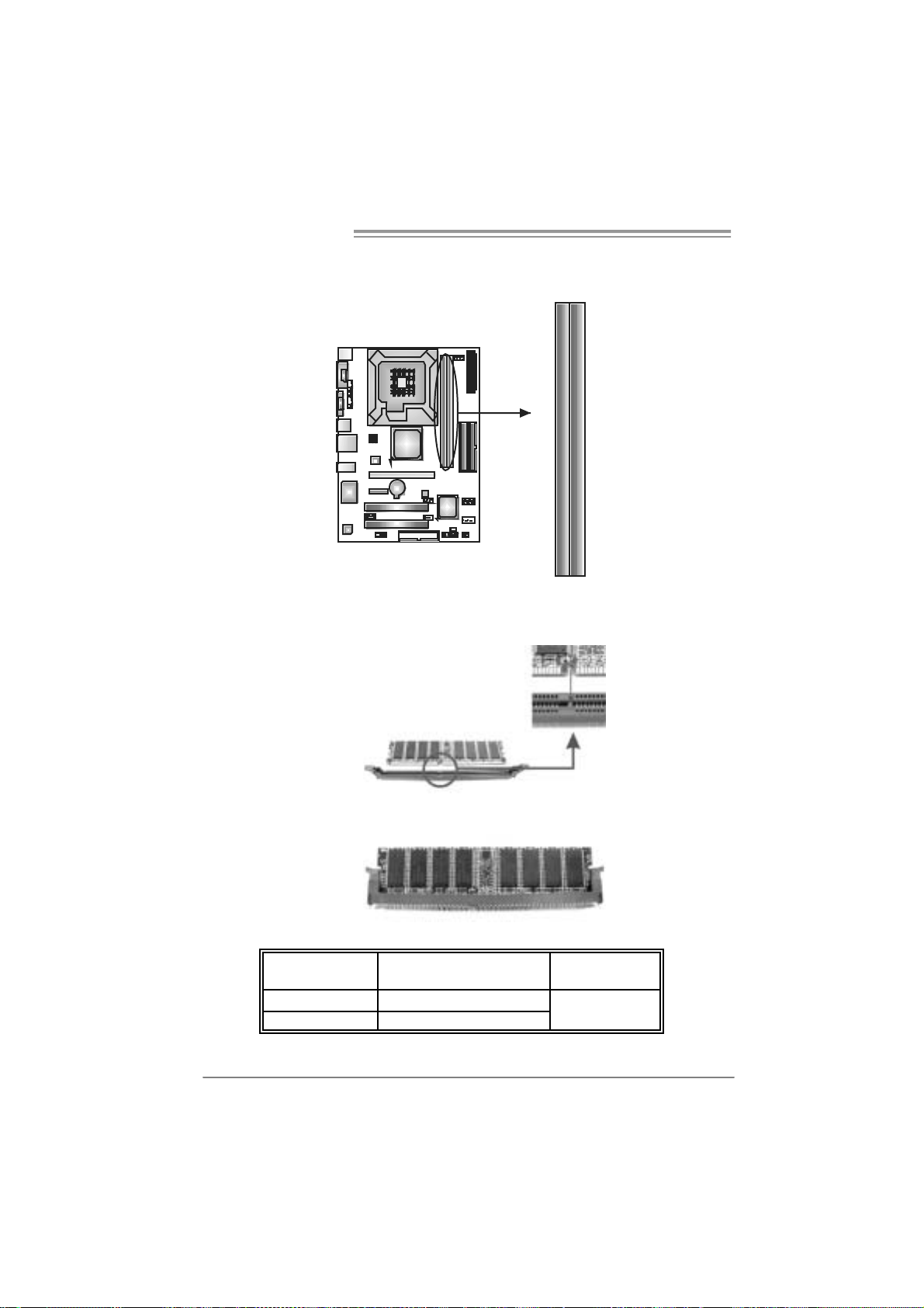
2.3 INSTALLING SYSTEM MEMORY
A. Me mo ry Modu le s
DIM M1
DIM M2
1. Unlock a DIMM slot by pressing the retaining clips outward. Align a
DIMM on the slot such that the notch on the DIMM matches the
break on the Slot.
2. Insert the DIMM vertically and firmly into the slot until the retaining
chip snap back in place and the DIMM is properly seated.
B. Memory Capacity
10
DI MM Socket
Location
DIMM1 256MB/512MB/ 1GB/2GB
DIMM2 256MB/512MB/ 1GB/2GB
DDR Module
To tal M e m o r y
Size
Max is 4GB.
P4M900-M7 SE/P4M890-M7 TE
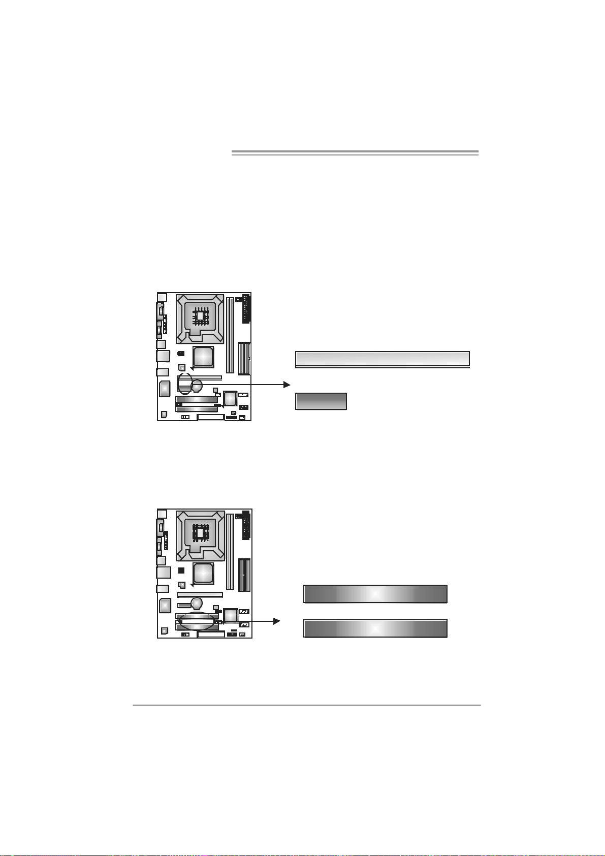
2.4 CONNECTORS AND SLOTS
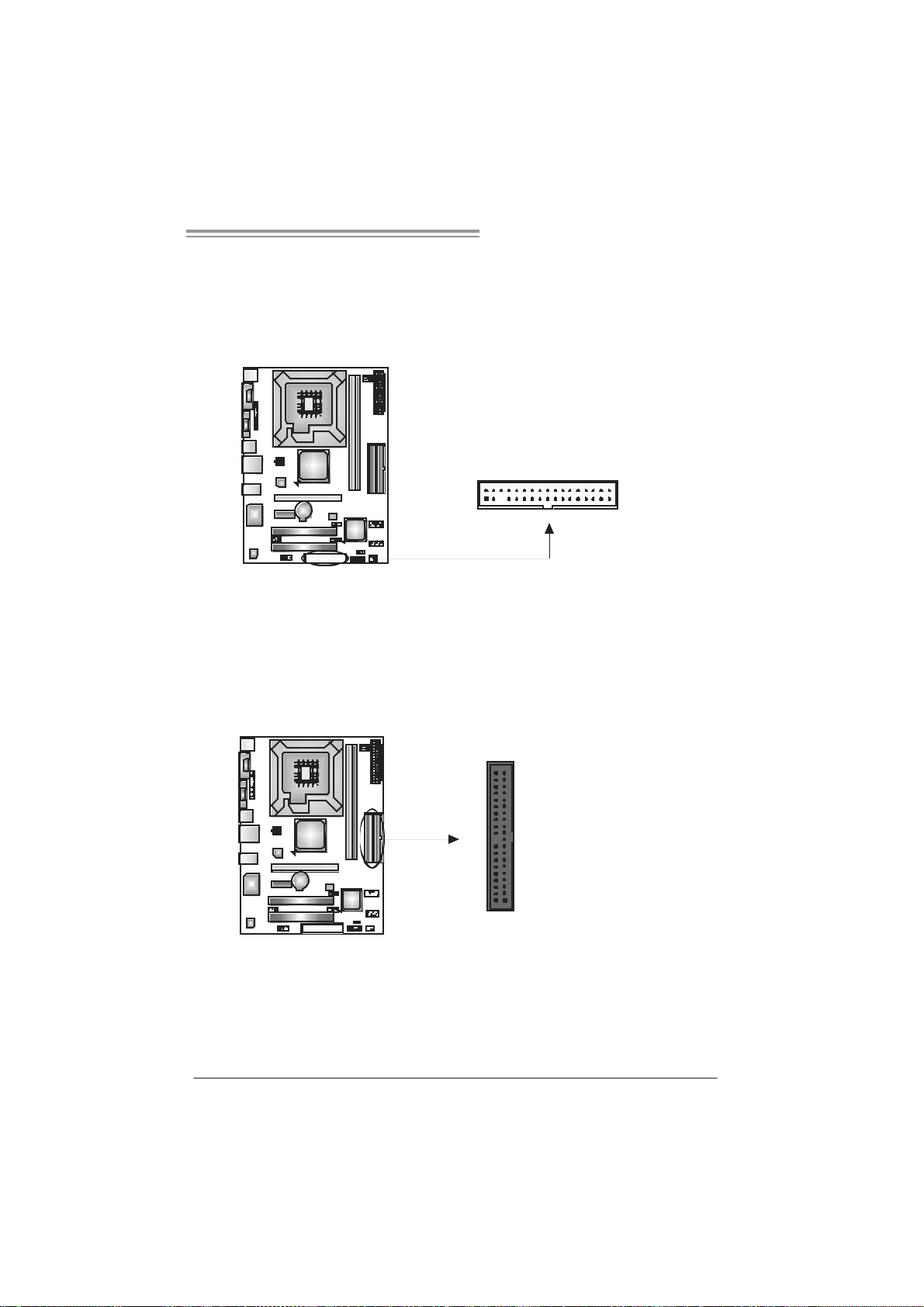
FDD1: Floppy Disk Conne c tor
The motherboard prov ides a standard floppy disk connector that supports 360K,
720K, 1.2M, 1.44M and 2.88M floppy disk ty pes. This connector s upports t he
prov ided f loppy driv e ribbon cable.
IDE1/IDE2 : Hard Disk Connec tors
The motherboard has a 32-bit Enhanced PCI ID E Controller that prov ides PIO
Mode 0~4, Bus Master, and Ultra DMA 33/66/100/133 f unc tionality. It has two
HDD connectors: IDE1 (primary ) and ID E2 (secondary).
The IDE connectors can connect a master and a slav e driv e, so you can
connect up to four hard disk drives. The f irs t hard drive should always be
connected to IDE1.
2
1
3940
21
34
33
IDE2IDE1
11
Motherboard Manual
PCI-EX16: PCI-Expr es s x1 6 S lot
- PCI-Express 1.0a compliant.
- Maximum theoret ical realized bandwidth of 4GB/s sim ultaneously per
direction, f or an aggregate of 8GB/ s totally.
PCI-EX1_1: PCI-Express x1 Sl ot
- PCI-Express 1.0a compliant.
- Data transf er bandwidth up t o 250MB/s per direction; 500MB/s in total.
- PCI-Express supports a raw bit-rat e of 2.5Gb/s on the data pins.
- 2X bandwidth ov er the traditional PCI archit ecture.
PCI-EX16
PCI-EX1_1
PCI1/PC I2: Peri phe ral Compo nent Interconnect Slots
This motherboard is equipped with 2 standard PCI slots. PCI stands f or
Peripheral Component Interconnect, and it is a bus standard for expansion
cards. This PCI slot is designated as 32 bits.
12
PCI1
PCI2
P4M900-M7 SE/P4M890-M7 TE
CHAPTER 3: HEADERS & JUMPERS SETUP
3.1 HOW TO SET UP JUMPERS
The illustration shows how to set up jumpers. When the jumper cap is
placed on pins, the jumper is “close”, if not, that means the jumper is
“open”.
Pin opened Pin closed Pin1-2 closed
3.2 DETAIL SETT INGS
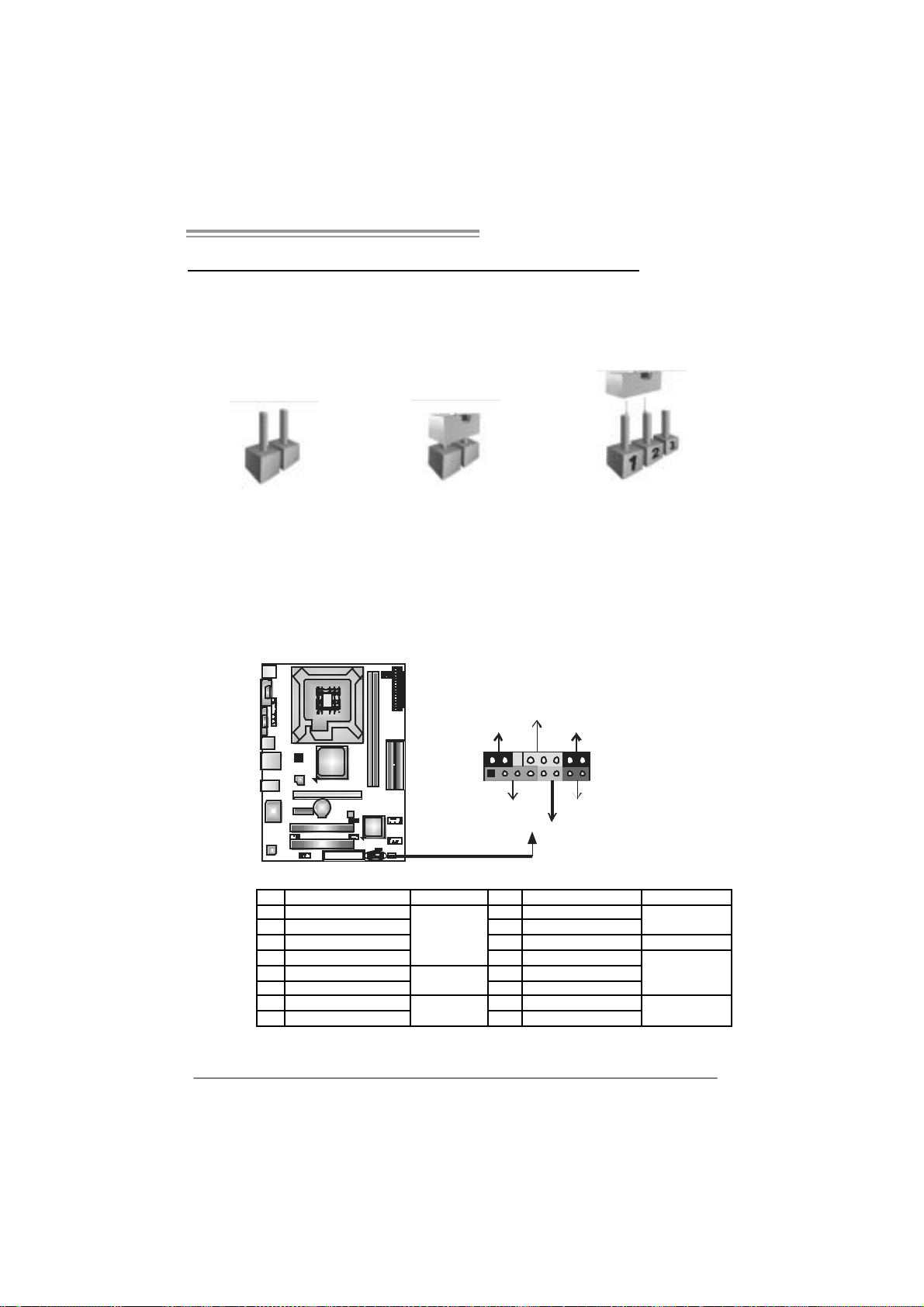
JPANEL1: Front Panel Header
This 16-pin connector includes Power-on, Reset, HDD LED, Power LED, Sleep
button and speaker connection. It allows user to c onnect the PC cas e’s f ront
panel switch functions.
PWR_LED
SLP
9
18
SPK
++
+
On /O ff
-
-
RS T
16
HL E D
Pin Assignment Function Pin Assignment Function
1 +5V 9 Sleep control
2 N/A 10 Ground
3 N/A 11 N/A N/A
4 Speaker
5 HDD LED (+) 13 P ower LED (+)
6 HDD LED (-)
7 Ground 15 Power button
8 Reset control
Speaker
Connector
Hard drive
LED
Reset button
12 P owe r LED (+)
14 P owe r LED (-)
16 Ground
Sleep button
Power LED
Power-on button
13
Motherboard Manual
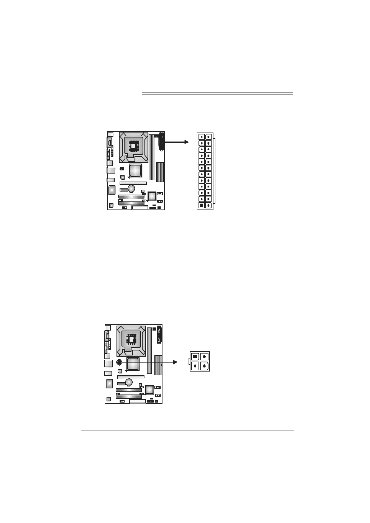
ATX Power So urce Connect or: JATXPWR1
JATXPWR1 allows user to connect 24-pin power connector on the ATX power
supply.
12
1
Pin Assignment Pin Assignment
24
13
13 +3.3V 1 + 3.3V
14 -12V 2 + 3.3V
15 Gr ound 3 Gr oun d
16 PS_ON 4 + 5V
17 Gr ound 5 Gr oun d
18 Gr ound 6 + 5V
19 Gr ound 7 Gr oun d
20 NC 8 PW_ OK
21 +5V 9 Standb y Vol t age+5V
22 +5V 10 +12V
23 +5V 11 +12V
24 Gr ound 12 +3.3V
JATXPWR 2: AT X Powe r Source Conne ctor
By connecting this connector, it will provide +12V to CPU power circuit.
Pin
1
23
4
Assignment
1 +12V
2 +12V
3 Ground
4 Ground
14
P4M900-M7 SE/P4M890-M7 TE
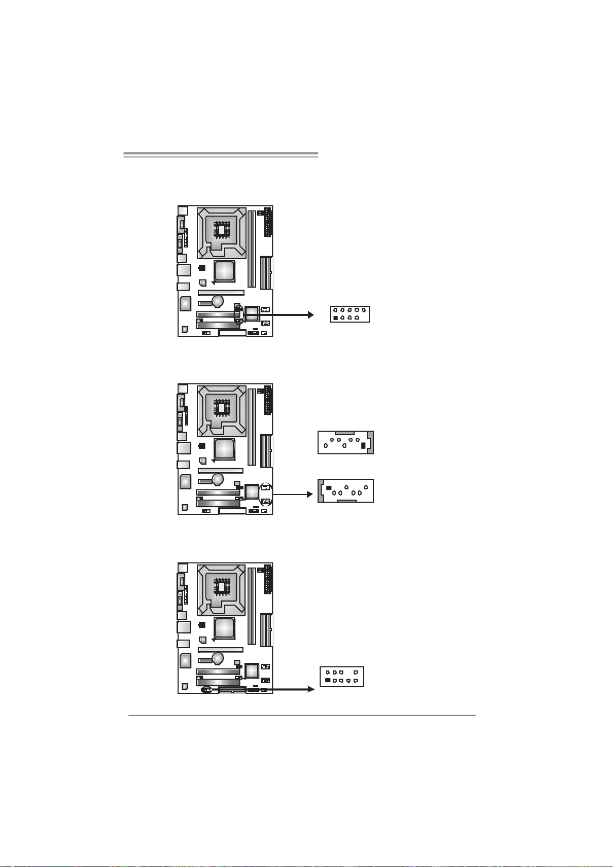
JUSB2/JUSB3: Headers for USB 2.0 Ports at Fron t Panel
This header allows user to connect additional USB cable on the PC f ront panel,
and also can be connected with internal USB devices, like USB card reader.
Assignment
Pin
1 +5V (fused)
2 +5V (fused)
3 USB4 USB5 USB+
6 USB+
7 Ground
210
19
JUSB2
JUSB3
8 Ground
9 Key
10 NC
JSATA1/JS ATA2: Serial ATA Connectors
The motherboard has a PCI to SATA Controller with 2 channels SATA interf ace,
it satisfies the SATA 1.0 spec and with transfer rate of 1.5Gb/s.
Pin
JSATA2
147
14 7
Assignment
1 Ground
2 TX +
3 TX 4 Ground
5 RX6 RX+
7 Ground
J SATA 1
JAUDIOF1 : Fron t Panel Au dio Header
This header allows user to connect the front audio output cable with the PC front
panel. It will disable the output on back panel audio connectors.
Pin Assignment
1 Mic Left in
2 Ground
3 Mic Right i n
4 GPIO
5 Right line i n
6 Jack Sense
7 Front Sens e
210
19
8 Key
9 Left l ine in
10 Jack Sense
15
 Loading...