


 Loading...
INSTALLATION GUIDE
AXIS M10 Series
AXIS M1011 Network Camera
AXIS M1011-W Network Camera
AXIS M1031-W Network Camera
AXIS M1054 Network Camera
ESPAÑOL ITALIANO DEUTSCH AISÇFRAN ENGLISH

Legal Considerations
Video and audio surveillance can be prohibited by laws that vary from country to country. Check the laws in your local region before using this product for surveillance purposes.
These network cameras include one (1) H.264 decoder license; and (1) MPEG-4 decoder license (AXIS M1054 excepted). To purchase further licenses, contact your reseller.
Electromagnetic Compatibility (EMC)
This equipment generates, uses and can radiate radio frequency energy and, if not installed and used in accordance with the instructions, may cause harmful interference to radio communications. However, there is no guarantee that interference will not occur in a particular installation.
If this equipment does cause harmful interference to radio or television reception, which can be determined by turning the equipment off and on, the user is encouraged to try to correct the interference by one or more of the following measures: Re-orient or relocate the receiving antenna. Increase the separation between the equipment and receiver. Connect the equipment to an outlet on a different circuit to the receiver. Consult your dealer or an experienced radio/TV technician for help. Shielded (STP) network cables must be used with this unit to ensure compliance with EMC standards. See Radio Transmission Regulatory Information & EMC, on page 113 for more information on this product’s compliance with radio frequency and safety standards.
Safety
Complies to EN 60950-1 (IEC 60950-1), Safety of Information Technology Equipment.
Equipment Modifications
This equipment must be installed and used in strict accordance with the instructions given in the user documentation. This equipment contains no user-serviceable components. Unauthorized equipment changes or modifications will invalidate all applicable regulatory certifications and approvals.
Liability
Every care has been taken in the preparation of this document. Please inform your local Axis office of any inaccuracies or omissions. Axis Communications AB cannot be held responsible for any technical or typographical errors and
reserves the right to make changes to the product and documentation without prior notice. Axis Communications AB makes no warranty of any kind with regard to the material contained within this document, including, but not limited to, the implied warranties of merchantability and fitness for a particular purpose. Axis Communications AB shall not be liable nor responsible for incidental or consequential damages in connection with the furnishing, performance or use of this material.
RoHS
This product complies with both the European RoHS directive, 2002/95/EC, and the Chinese RoHS regulations, ACPEIP.
WEEE Directive
The European Union has enacted a Directive 2002/96/EC on Waste Electrical and Electronic Equipment (WEEE Directive). This directive is
applicable in the European Union member states.
The WEEE marking on this product (see right) or its documentation indicates that the product must not be disposed of together with household waste. To prevent possible harm to human health and/or the environment, the product must be disposed of in an approved and environmentally safe recycling process. For further information on how to dispose of this product correctly, contact the product supplier, or the local authority responsible for waste disposal in your area.
Business users should contact the product supplier for information on how to dispose of this product correctly. This product should not be mixed with other commercial waste. For more information, visit www.axis.com/techsup/.
Support
Should you require any technical assistance, please contact your Axis reseller. If your questions cannot be answered immediately, your reseller will forward your queries through the appropriate channels to ensure a rapid response. If you are connected to the Internet, you can:
•download user documentation and firmware updates
•find answers to problems in the FAQ database. Search by product, category, phrases.
•report problems to Axis support by logging in to your private support area.
AXIS M10 Series |
Page 3 |
AXIS M10 Series Installation Guide
This guide helps you to install the AXIS M10 Series Network Camera on your network. For further information, please see the User’s Manual available on the CD, or from www.axis.com/techsup
Installation steps
1.Check the package contents against the list below.
2.Hardware overview on page 4.
3.Install the hardware on page 8.
4.Assign an IP address on page 10.
5.Set the password on page 13.
6.Configure the wireless connection on page 15.
(AXIS M1011-W/M1031-W only)
Important!
This product must be used in compliance with local laws and regulations.
Package contents
Item |
Models/variants/notes |
|
|
Network Camera |
AXIS M1011, AXIS M1011-W, AXIS M1031-W, |
|
AXIS M1054 |
|
|
Indoor power |
PS-H* or PS-V |
adaptor |
Europe, UK, USA/Japan, Australia, Korea, Argentina, China |
(country specific) |
*power adaptor extension cable 1.8m (5.9ft), PS-H only |
|
|
Extension tube |
• Attached short extension tube, 4 mounting screws/plugs |
|
• 1 long extension tube, 1 cable clip, 1 tube joint (AXIS |
|
M1054 only) |
|
|
Flexible clamp |
For shelf mounting |
|
|
CD |
AXIS Network Video Product CD, including product |
|
documentation, installation tools and other software |
|
|
Printed Materials |
AXIS M10 Series Installation Guide (this document) |
|
Axis Warranty Document |
|
|
ENGLISH
Page 4 |
AXIS M10 Series |
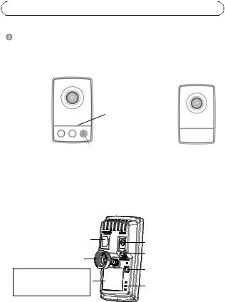
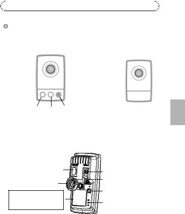
Hardware overview
Front view - AXIS M1031-W/AXIS M1054 AXIS M1011/-W
Lens with |
Lens with |
|
|
||||
Status Indicator |
|
|
|
|
|
||
|
|
|
Status Indicator |
|
|
|
|
LED |
|
|
|
||||
|
|
|
|||||
|
|
|
|
||||
|
|
|
Microphone |
LED |
|
|
|
|
|
|
|
|
|
|
|
|
|
|
|
|
|
|
|
|
|
|
|
|
|
|
|
Light PIR Speaker
sensor
Rear view (all models)
Network connector |
Power connector |
|
|
||
Lock ring |
I/O connector |
|
(AXIS M1054 only) |
||
|
||
Product number (P/N) & |
Control button |
|
|
||
Serial number (S/N). |
Power Indicator LED |
|
The serial number may be |
Network Indicator LED |
|
required during the installation. |
||
|
||
|
Wireless Indicator LED |
|
|
(activated on wireless models only) |

AXIS M10 Series |
Page 5 |
Unit connectors
Network connector - RJ-45 Ethernet connector; shielded cables recommended.
Power connector - Mini DC connector 5.0-5.1V DC, Max 1.5A. Center pin +.
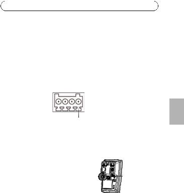
I/O terminal connector (AXIS M1054 only)
The 4-pin I/O terminal connector provides the interface to 1 transistor output, 1 digital input, auxiliary power, GND.
The terminal connector is used in applications for motion detection, event triggering, alarm notification via email, and image storage to FTP locations.
•Input - for connecting a push button, for example. If the push button is pressed, the state changes and the input becomes active (shown under Events > Port Status).
•Output - connects an alarm device that can be activated by Output buttons on the Live View page, or by an Event Type. The output shows as active (Events > Port Status) if the alarm device is activated.
Function |
Pin |
Notes |
|
|
|
|
|
|
|
|
|
|
|
GND |
1 |
Ground |
|
|
|
|
|
|
|
|
|||
3.3V DC |
2 |
Can be used to power auxiliary equipment. |
||||
Power |
|
Note: This pin can only be used as power out. |
||||
|
|
|
|
|||
Digital Input |
3 |
Connect to GND to activate, or leave floating (or |
||||
|
|
unconnected) to deactivate. |
||||
|
|
|
|
|
|
|
Transistor |
4 |
|
|
|
|
Uses an open-drain NFET transistor |
Output |
|
|
|
|
|
with the source connected to GND. If |
|
|
|
|
|
|
used with an external relay, a |
|
|
|
|
|
|
diode must be connected in parallel |
|
|
|
|
|
|
|
|
|
Pin 4 |
|
|
|
with the load, for protection against |
|
|
|
Pin 2 |
|
voltage transients. |
|
|
|
|
Pin 3 |
|
Pin 1 |
|
|
|
|
|
|
||
|
|
|
|
|
|
|
ENGLISH

Page 6 |
AXIS M10 Series |
Connect input/output devices to the camera as follows:
1. Attach the cables for the device securely to the supplied connector block.
2. Once the cables are connected, attach |
I/O connector |
||
the connector block to the terminal |
|
||
connector on the camera. |
|
||
LED indicators |
|
|
|
LED |
Color |
Indication |
|
Network |
Green |
Steady for connection to a 100 Mbit/s network. Flashes |
|
|
|
for network activity. |
|
|
Amber |
Steady for connection to 10 Mbit/s network. Flashes for |
|
|
|
network activity. |
|
|
Unlit |
No network connection. |
|
|
|
Note: Configure Network LED to be unlit during normal |
|
|
|
operation, from Setup > System Options > LED settings. |
|
|
|
See the online help files for more information. |
|
Status |
Green |
Steady green for normal operation. |
|
|
|
Note: Configure the Status LED to be unlit during normal |
|
|
|
operation, or to flash only when the camera is accessed |
|
|
|
from Setup > System Options > LED. See the online help |
|
|
|
files for more information. |
|
|
Amber |
Steady during startup, reset to factory default or when |
|
|
|
restoring settings. |
|
|
Red |
Slow flash for failed upgrade. |
|
Power |
Green |
Normal operation. |
|
|
Amber |
Flashes green/amber during firmware upgrade. |
|
Wireless |
Unlit |
Wired mode. |
|
|
Green |
Steady for connection to a wireless network. Flashes for |
|
|
|
network activity. |
|
|
Red |
Steady for no wireless network connection. Flashes when |
|
|
|
scanning for wireless networks. |
|

AXIS M10 Series |
Page 7 |
AXIS M1031-W and AXIS M1054 only
AXIS M1031-W and AXIS M1054 are equipped with the following:
PIR sensor - passive infrared sensor that measures infrared light from passing objects in its field of view. When configured, the camera can automatically switch on the light when triggered by the PIR sensor.
Sensitivity range up to 5m (16ft).
Light - the camera can be configured so that the white illumination LED is triggered by the PIR sensor; this can also be done via the web pages -
Setup > Live View Config > Light buttons. The light is designed for temporary use and should not be permanently lit.
Microphone/speaker for half duplex audio; full-duplex for AXIS M1054.
For more information see the product’s User’s Manual located on the Axis web site at www.axis.com or on the Axis Network Video Product CD.
ENGLISH
Page 8 |
AXIS M10 Series |
 Install the hardware
Important!
AXIS M10 Series is not approved for outdoor use - the product may be installed in indoor environments only.
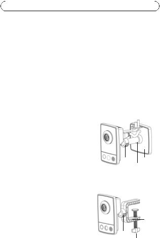
Mount the camera
AXIS M10 Series is shipped with the base plate and a short extension tube mounted. Unscrew the extension tube to release the base plate from the cover plate. Depending on whether the camera is to be mounted on a wall or shelf, follow the appropriate instructions below.
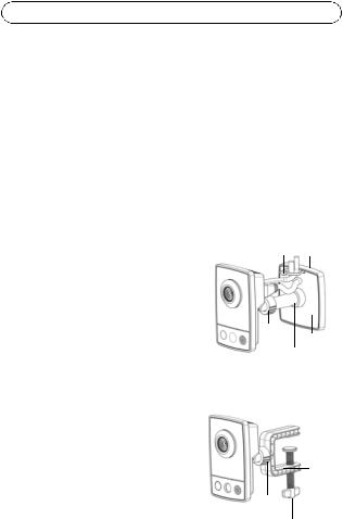
Wall mounting
1.Using the supplied screws, fix the base plate to a flat (horizontal or vertical) surface.
2.Place the cover plate over the base plate; if needed attach the short extension tube, and/or one or more of the long extension tubes (AXIS M1054 only) provided.
3.Attach the camera, adjust the angle and tighten the lock ring.
4.Secure the cables once connected, with the cable tie that is attached to the cover plate.
Shelf mounting
1.Position the clamp and tighten the fixing screw securely.
2.Attach the camera’s lock ring to the clamp, adjust the camera’s angle and tighten the lock ring.
Wall mount |
|
Base plate |
|
Cable tie |
|
||
|
|
||
|
|
|
|
|
|
|
|
Lock ring Cover plate
Extension tube (optional)
Shelf mount
Clamp
Lock ring
Fixing screw
AXIS M10 Series |
|
Page 9 |
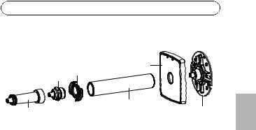
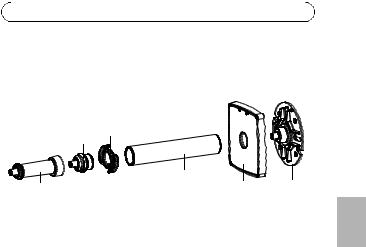
Assembly with extension tubes |
|
|
|
Base cover |
|
Tube joint cable clip |
|
|
Short extension tube |
Long extension tube |
Base plate |
|
Connect the cables
1.Connect the camera to the network using a shielded network cable. AXIS M1054 supports Power over Ethernet. If connecting to a wireless network (AXIS M1011-W/M1031-W), the wired connection is temporary in order to configure the camera’s wireless settings. See page 15 for more information.
2.Connect the supplied indoor power adaptor to the camera’s power connector. Skip this step if PoE is used in the case of AXIS M1054.
3.Check that the indicator LEDs indicate the correct conditions (see page 6). Note that some LEDs can be disabled and may be unlit.
ENGLISH

Page 10 |
AXIS M10 Series |
 Assign an IP address
Most networks today have a DHCP server that automatically assigns IP addresses to connected devices. If your network does not have a DHCP server, the Network Camera will use 192.168.0.90 as the default IP address.
AXIS IP Utility and AXIS Camera Management are the recommended methods for setting an IP address in Windows. These free applications are available on the Axis Network Video Product CD supplied with this product, or they can be downloaded from www.axis.com/techsup Depending on the number of cameras you wish to install, use the method that suits you best.
Method |
Recommended for |
Operating system |
|
|
|
AXIS IP Utility |
Single camera |
Windows |
See page 11 |
Small installations |
|
|
|
|
AXIS Camera |
Multiple cameras |
Windows 2000 |
Management |
Large installations |
Windows XP Pro |
See page 12 |
Installation on a different |
Windows 2003 Server |
|
subnet |
Windows Vista |
|
|
|
Notes:
•If assigning the IP address fails, check that there is no firewall blocking the operation.
•For other methods of assigning or discovering the IP address of the AXIS M10 Series, such as in other operating systems, see page 19.
AXIS M10 Series |
Page 11 |
AXIS IP Utility - single camera/small installation
AXIS IP Utility automatically discovers and displays Axis devices on your network. You can also manually set a static IP address
through this application. AXIS IP Utility is available on the Axis Network Video Product CD, or it can be downloaded from www.axis.com/techsup
Install the AXIS M10 Series Network Camera on the same network segment (physical subnet) as the computer running AXIS IP Utility.
Automatic discovery
1.Check that the AXIS M10 Series Network Camera is connected to the network and that power has been applied.
2.Start AXIS IP Utility.
3.When the AXIS M10 Series network camera appears in the window, double-click to open the camera’s home page.
4.See page 13 for instructions on how to set the password.
Set the IP address manually (optional)
1.Acquire an unused IP address on the same network segment your computer is connected to.
2.Select the AXIS M10 Series in the list.
3.Click the button  Assign new IP address to selected device and enter the IP address.
4.Click the Assign button and follow on-screen instructions. Note that the camera must be restarted within two minutes for the new IP address to be set.
5.Click the Home Page button to access the camera’s web pages.
6.See page 13 for instructions on how to set the password.
ENGLISH
Page 12 |
AXIS M10 Series |
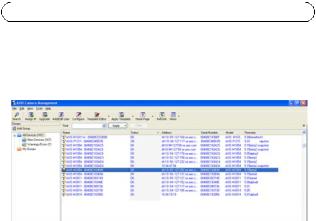
AXIS Camera Management - multiple cameras/large installations
AXIS Camera Management can automatically discover multiple Axis devices, show connection status, manage firmware upgrades and set IP addresses.
Automatic discovery
1.Check that the camera is connected to the network and that power has been applied.
2.Start AXIS Camera Management. When the camera appears in the window, right-click the link and select Live View Home Page.
3.See page 13 for instructions on how to set the password.
Assign an IP address in a single device
1.Select AXIS M1011 in AXIS Camera Management and click the
Assign IP button  .
.
2.Select Assign the following IP address and enter the IP address, subnet mask and default router the device will use.
3.Click the OK button.

AXIS M10 Series |
Page 13 |
Assign IP addresses in multiple devices
AXIS Camera Management speeds up the process of assigning IP addresses to multiple devices, by suggesting IP addresses from a specified range.
1.Select the devices you wish to configure (different models can be selected) and click the Assign IP button  .
.
2.Select Assign the following IP address range and enter the range of IP addresses, the subnet mask and default router the devices will use.
3.Click the OK button.
Set the password
To gain access to the product, the password for the default administrator user root must be set. This is done in the ‘Configure Root Password’ dialog, which is displayed when the AXIS M10 Series is accessed for the first time.
To prevent network eavesdropping when setting the root password, this can be done via an encrypted HTTPS connection, which requires an HTTPS certificate (see note below).
To set the password via a standard HTTP connection, enter it directly in the first dialog shown below.
To set the password via an encrypted HTTPS connection, follow these steps:
1.Click the Create self-signed certificate button.
2.Provide the requested information and click OK. The certificate is created and the password can now be set securely. All traffic to and from the AXIS M10 Series is encrypted from this point on.
ENGLISH

Page 14 |
AXIS M10 Series |
3.Enter a password and then re-enter it to confirm the spelling. Click OK. The password has now been configured.
To create an HTTPS connection, start
 by clicking this button.
To configure the
password directly via an unencrypted connection, enter the password here.
4.To log in, enter the user name “root” in the dialog as requested Note: The default administrator user name”root” cannot be deleted.
5.Enter the password as set above, and click OK.
If required, click Yes to install AMC (AXIS Media Control), which allows viewing of the video stream in Internet Explorer. You will need administrator rights on the computer to do this. If required, click the link to install missing decoders. The Live View page of the AXIS M10 Series network camera appears. The Setup link to the right gives you menu options that allow you to customize the camera.
AXIS M1011/ AXIS M1054: The installation is now complete. AXIS M1011-W/M1031-W: Proceed to Configure the wireless connection, on page 15.

AXIS M10 Series |
Page 15 |
Configure the wireless connection
AXIS M1011-W/M1031-W is temporarily connected to the wired network to allow configuration of the camera’s wireless settings before connecting to the wireless network. Configuring the camera using an unsecured wireless connection is not recommended, as passphrases and keys are sent in plain text.
Note: For even greater security, use HTTPS. Once the camera has been connected to the wired network, go to Setup > System Options > Security > HTTPS and refer to the camera’s online help for instructions.
Status of Wireless Networks
Go to Setup > Basic Setup > Wireless in the camera’s internal web pages.
This list is the result of a network scan. The network the AXIS M1011-W/ M1031-W is currently linked to is shown in blue. A network using unsupported security is shown in grey. The following information is provided:
•SSID - The name of a wireless network (or ad-hoc device).
•Mode - An Access Point (Master) or Ad-Hoc device.
•Security - Indicates the type of security the network uses. See below for the supported security types.
•Channel - Shows the wireless channel currently in use.
•Signal strength - Shows the signal strength.
•Bit rate - The current bit rate in Mbit/s. This is only shown for
the access point currently in use.
Note: Access points with a disabled SSID Broadcast will not appear unless the SSID is manually entered.
ENGLISH

Page 16 |
AXIS M10 Series |
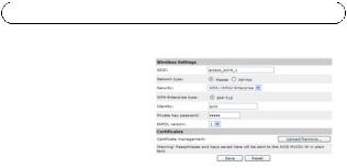
Wireless Settings
1.Select an access point or ad-hoc device under Status of Wireless Networks; some of the required information will automatically be entered under Wireless Settings.
2.SSID is the name of the selected wireless network. Leave this field blank if AXIS M1011-W/M1031-W is to access the nearest unsecured network.
3.Network type - select Master to access the network via an access point or Ad-hoc to access any other wireless device and create a local network (see note below).
4.Security - select one of the following methods:
•WPA-/WPA2-PSK
•WPA-/WPA2-Enterprise - see instructions below
•WEP - see instructions below
•No security (not recommended)
Keys, passphrases and certificates that are used for security must be entered manually. To retrieve the necessary details, contact the Network Administrator for the selected access point or ad-hoc device.
5.Click Save.
Note: Ad hoc mode allows users to form a wireless LAN without connection via an access point. The camera can, for example, connect point-to-point to a laptop with wireless network support. Adhoc connection may be useful in certain installations but is not the recommended method.
WPA-/WPA2-PSK - Enter the required Pre-shared Key for the access point, which can be a hexidecimal number (Manual hex) or a passphrase.
WPA-/WPA2-Enterprise - Choose the type of client/server authentication being used by the access point; EAP-TLS.
AXIS M10 Series |
Page 17 |
|
|
EAP-TLS |
|
|
|
• |
Identity - Enter the user |
|
|
|
identity to present to the |
|
|
|
network |
|
|
• |
Private key password - |
|
|
|
Enter the password for |
|
|
|
your user identity |
|
ENGLISH |
• EAPOL version - Select the |
|
||
|
|
||
|
version used (1 or 2) in your access point |
|
|
• |
Certificates - Upload a CA certificate to present to the access point |
|
|
|
|||
|
for authentication |
|
|
WEP
Authentication - Select Open or Shared Key, depending on the method used by your access point. Not all access points have this option, in which case they probably use Open System, which is sometimes known as SSID Authentication.
Key length - This sets the length of the key used for the wireless encryption, 64 or 128 bit. The encryption key length may also be shown as 40/64 and 104/128.
Key type - The available key types depend on the selected access point. The following options are available in the camera:
•Manual - Allows you to manually enter the hex key.
•ASCII - The string must be exactly 5 characters for 64-bit WEP and 13 characters for 128-bit WEP.
•Passphrase - In 64-bit WEP, the Passphrase generates 4 different keys. For 128-bit WEP, only 1 key is generated, which is then replicated for all 4 keys. Key generation is not standardized and can differ from brand to brand. Check that the generated keys are identical to those in your access point - if not, they must be entered manually.

Page 18 |
AXIS M10 Series |
Complete the wireless installation
1.Check that the wireless settings in the camera correspond to the settings in the access point.
2.Disconnect the network cable from the camera.
3.Refresh the web page after 20-30 seconds to confirm the wireless connection. If the camera cannot be accessed, run AXIS IP Utility and select it from the list.
Notes:
•To establish communication, the wireless settings must be exactly the same in the camera as in the access point or ad-hoc device.
•Keys, passphrases and certificates that are used for security must be entered manually. Contact your Network Administrator for the requirements for the selected access point or ad-hoc device.
•Wireless settings must always (during installation and at all other times) be configured or changed in the camera first, before changing the settings in the wireless access point. This ensures that the camera is always accessible when making changes.
•SSID (Service Set Identifier) is sometimes written as ESSID (Extended Service Set Identifier).
The installation for AXIS M1011-W/M1031-W is now complete.

AXIS M10 Series |
|
Page 19 |
|
|
Other methods of setting the IP address |
|
|||
|
|
|
|
|
|
Use in |
Notes |
|
|
|
operating |
|
|
|
|
system |
|
|
|
|
|
|
|
|
UPnP™ |
Windows |
When enabled on your computer, the camera |
|
|
|
(ME or |
is automatically detected and added to “My |
|
ENGLISH |
|
XP) |
Network Places.” |
|
|
|
|
|
||
|
|
|
|
|
Bonjour |
MAC OSX |
Applicable to browsers with support for |
|
|
|
(10.4 or |
Bonjour. Navigate to the Bonjour bookmark |
|
|
|
later) |
in your browser (e.g. Safari) and click on the |
|
|
|
|
|||
|
|
link to access the camera’s web pages. |
|
|
|
|
|
|
|
AXIS Dynamic |
All |
A free service from Axis that allows you to |
|
|
DNS Service |
|
quickly and simply install your camera. |
|
|
|
|
Requires an Internet connection with no HTTP |
|
|
|
|
proxy. See www.axiscam.net for more |
|
|
|
|
information. |
|
|
|
|
|
|
|
ARP/Ping |
All |
See user’s manual. The command must be |
|
|
|
|
issued within 2 minutes of connecting power |
|
|
|
|
to the camera. |
|
|
|
|
|
|
|
View DHCP server |
All |
To view the admin pages for the network |
|
|
admin pages |
|
DHCP server, see the server’s documentation. |
|
|
|
|
|
|
|
Resetting to the Factory Default Settings
To reset all parameters and the IP address to Factory Default settings:
1.Disconnect power from the camera.
2.Press and hold the Control button and reconnect power.
3.Keep the Control button pressed until the Status indicator flashes amber (this may take up to 15 seconds).
4.Release the Control button. When the Status indicator displays green (which can take up to 1 minute) the process is complete and the camera has been reset.

Page 20 |
AXIS M10 Series |
5.Re-assign the IP address, using any one of the methods.
Accessing the camera from the Internet
Once installed, your AXIS M10 Series network camera is accessible on your local network (LAN). To access the camera from the Internet, configure network routers to allow incoming traffic, which is usually done on a specific port:
•HTTP port (default port 80) for viewing and configuration
•RTSP port (default port 554) for viewing H.264 video streams Please refer to the documentation for your router for further
instructions. For more information on this and other topics, visit the Axis Support Web at www.axis.com/techsup
Further information
The user’s manual is available from the Axis Web site at www.axis.com or from the Axis Network Video Product CD supplied with this product.
Visit www.axis.com/techsup to check if there is updated firmware available for the AXIS M10 Series. To see the currently installed firmware version, see Setup > About in the camera’s web pages.
Série AXIS M10 |
Page 21 |
Guide d’installation de la Série AXIS M10
Ce guide est destiné à vous aider à installer la Caméra réseau de la Série AXIS M10 sur votre réseau. Pour tout complément d’information, veuillez vous reporter au Guide de l’utilisateur présent sur le CD ou sur www.axis.com/techsup.
Procédure d’installation
1.Vérifier que l’emballage contient bien tous les éléments de la liste ci-dessous.
2.Présentation du matériel. Voir page 23.
3.Installation du matériel. Voir page 28.
4.Attribution d’une adresse IP. Voir page 30.
Important !
Ce produit doit être utilisé conformément à la législation locale.
5.Configuration du mot de passe. Voir page 34.
6.Configuration de la connexion sans fil. Voir page 36. (AXIS M1011-W/M1031-W uniquement)
AISÇFRAN
Page 22 |
Série AXIS M10 |
Contenu de l’emballage
Élément |
Modèles/variantes/remarques |
|
|
Caméra réseau |
AXIS M1011, AXIS M1011-W, AXIS M1031-W, AXIS M1054 |
|
|
Adaptateur |
PS-H* ou PS-V |
secteur d’intérieur |
Europe, Royaume-Uni, États-Unis/Japon, Australie, Corée, |
(selon le pays) |
Argentine, Chine |
|
*prolongateur de câble de 1,8 m pour l’adaptateur secteur, |
|
PS-H uniquement |
|
|
Tube d'extension |
• Tube d'extension court fixé, 4 vis/chevilles de fixation |
|
• 1 tube d'extension long, 1 clip pour câble, 1 joint pour |
|
tube (AXIS M1054 uniquement) |
|
|
Pince flexible |
Pour montage sur tablette |
|
|
CD |
CD de la caméra vidéo réseau Axis, comprenant une |
|
documentation, des outils d’installation et des logiciels |
|
complémentaires |
|
|
Documentation |
Série AXIS M10 Guide d'installation (le présent document) |
imprimée |
Document de garantie d’Axis |
|
|
Série AXIS M10 |
|
|
|
Page 23 |
||
Présentation du matériel |
|
|
|
|
||
Vue avant - AXIS M1031-W/AXIS M1054 |
AXIS M1011/-W |
|||||
Objectif avec |
Objectif avec |
|||||
témoin DEL |
|
|
||||
|
||||||
d’état |
témoin DEL |
|
|
|||
|
||||||
|
|
Microphone |
d’état |
|
|
|
|
|
|
|
|
|
|
Projecteur Capteur Haut-parleur
infrarouge
Vue arrière (tous les modèles)
Connecteur réseau |
Connecteur d'alimentation |
|
|
||
Bague de blocage |
Connecteur E/S |
|
(AXIS M1054 uniquement) |
||
|
||
Référence produit (P/N) et |
Bouton de commande |
|
|
||
Numéro de série (S/N). |
Témoin DEL d’alimentation |
|
Le numéro de série peut être |
Témoin DEL réseau |
|
demandé pendant l’installation. |
||
|
||
|
Témoin DEL sans fil |
|
|
(activé sur les modèles sans fil uniquement). |
AISÇFRAN

Page 24 |
Série AXIS M10 |
Connecteurs de l’unité
Connecteur réseau - Connecteur Ethernet RJ-45. Il est recommandé d’utiliser des câbles blindés.
Connecteur d'alimentation - Miniconnecteur CC. 5,0-5,1 V CC, max. 1,5 A. Broche centrale +.
Connecteur pour terminaux E/S (AXIS M1054 uniquement)
Le connecteur pour terminaux E/S à quatre broches assure l’interface avec 1 sortie transistor, 1 entrée numérique, l’alimentation auxiliaire et la mise à la terre.
Le connecteur pour terminaux est utilisé dans les applications de détection de mouvement, de déclenchement d’événements, de notifications d’alarmes par courrier électronique, ou encore à des fins de stockage d’images sur FTP.
•Entrée – permet de connecter par exemple un bouton-poussoir. Lorsque le bouton est enfoncé, l’état change et l’entrée devient active (comme indiqué sous Events > Port Status [Événements > État du port]).
•Sortie – permet de brancher un dispositif d’alarme pouvant être activé à l’aide de boutons de sortie sur la page Live View [Visualisation en direct], ou via un type d’événement. La sortie est signalée active (Events > Port Status [Événement > État du port]) si le dispositif d’alarme est activé.
Série AXIS M10 |
|
|
|
Page 25 |
|
|
|
|
|
|
|
Fonction |
Broche |
Remarques |
|
||
|
|
|
|
|
|
GND |
1 |
Mise à la terre |
|
||
|
|
|
|
||
Alimentatio |
2 |
Peut servir à alimenter le matériel auxiliaire. |
|||
n 3,3 V CC |
|
Remarque : Cette broche ne peut être utilisée que |
|||
|
|
comme sortie d’alimentation. |
|||
|
|
|
|
||
Entrée |
3 |
Peut être connectée à GND pour l’activer ou rester |
|||
numérique |
|
pendu (ou déconnectée) si on préfère ne pas l’activer. |
|||
|
|
|
|
|
|
Sortie |
4 |
|
|
|
Utilise un transistor NFET à drain |
transistor |
|
|
|
|
ouvert avec la source connectée |
|
|
|
|
|
au GND. En cas d’utilisation avec |
|
|
|
|
|
un relais externe, une |
|
|
|
|
|
|
|
|
Pin 4 |
|
|
diode doit être connectée en |
|
|
|
Pin 2 |
parallèle avec la charge, en guise |
|
|
|
|
Pin 3 |
Pin 1 |
|
|
|
|
de protection contre les tensions |
||
|
|
|
|
|
|
|
|
|
|
|
transitoires. |
|
|
|
|
|
|
Pour connecter des périphériques d’entrée ou de sortie à la caméra, procédez comme suit :
1. Connectez les câbles destinés au |
|
périphérique au bloc connecteur |
|
fourni. |
Connecteur E/S |
2. Une fois les câbles branchés, attachez le bloc connecteur au connecteur pour terminaux de la caméra.
AISÇFRAN

Page 26 |
Série AXIS M10 |
Témoins DEL
DEL |
Couleur |
Indication |
|
|
|
|
|
Réseau |
Vert |
Continu en cas de connexion à un réseau de 100 Mbits/s. |
|
|
|
Clignote en cas d'activité réseau. |
|
|
|
|
|
|
Orange |
Continu en cas de connexion à un réseau de 10 Mbits/s. |
|
|
|
Clignote en cas d'activité réseau. |
|
|
|
|
|
|
Éteint |
Pas de connexion réseau. |
|
|
|
Remarque : Le témoin DEL peut être configuré pour être |
|
|
|
éteint au cours du fonctionnement normal. Pour ce faire, |
|
|
|
cliquez sur Setup > System Options > LED settings |
|
|
|
[Configuration > Options système > Paramètres DEL]. |
|
|
|
Reportez-vous à l’aide en ligne pour plus d’informations. |
|
|
|
|
|
État |
Vert |
Vert continu en cas de fonctionnement normal. |
|
|
|
Remarque : Le témoin DEL peut être configuré pour être |
|
|
|
éteint au cours du fonctionnement normal, ou pour |
|
|
|
clignoter uniquement lors des accès à la caméra. Pour ce |
|
|
|
faire, cliquez sur Setup > System Options > LED |
|
|
|
[Configuration > Options système > DEL]. Reportez- |
|
|
|
vous à l’aide en ligne pour plus d’informations. |
|
|
|
|
|
|
Orange |
En continu pendant le démarrage, la réinitialisation des |
|
|
|
valeurs d’usine ou la restauration des paramètres. |
|
|
|
|
|
|
Rouge |
Clignote lentement en cas d'échec de la mise à niveau. |
|
|
|
|
|
Alimentat |
Vert |
Fonctionnement normal. |
|
ion |
|
|
|
Orange |
Clignote en vert/orange pendant la mise à niveau des |
||
|
|||
|
|
microprogrammes. |
|
|
|
|
|
Sans fil |
Éteint |
Mode avec fil. |
|
|
|
|
|
|
Vert |
Continu en cas de connexion à un réseau sans fil. Clignote |
|
|
|
en cas d'activité réseau. |
|
|
|
|
|
|
Rouge |
Continu en l'absence de connexion à un réseau sans fil. |
|
|
|
Clignote lors de la recherche de réseaux sans fil. |
|
|
|
|

Série AXIS M10 |
Page 27 |
AXIS M1031-W et AXIS M1054 uniquement
Les caméras AXIS M1031-W et AXIS M1054 sont en outre équipées des éléments suivants :
Capteur infrarouge passif – Le capteur infrarouge passif mesure la lumière infrarouge des objets traversant son champ de vision. Si la caméra est configurée en ce sens, elle peut automatiquement allumer la lumière en cas de déclenchement par le capteur infrarouge passif. Sensibilité : jusqu’à 5 m.
Projecteur – Le projecteur à DEL blanche peut être configuré pour être déclenché par le capteur infrarouge passif. Vous pouvez également configurer son déclenchement à partir des pages Web, sous Setup > Live View Config > Light buttons [Configuration > Configuration de la vidéo en direct > Boutons projecteur]. Le projecteur doit être utilisé de manière temporaire et non permanente.
Microphone/haut-parleur – Pour la transmission audio semi-duplex ; duplex intégral avec l’AXIS M1054.
Pour tout complément d’information, reportez-vous au manuel d’utilisation disponible sur le site Web www.axis.com ou sur le CD accompagnant votre caméra réseau Axis.
AISÇFRAN
Page 28 |
Série AXIS M10 |
 Installation du matériel
Important !
L’AXIS M10 Series n’est pas conçue pour un usage à l’extérieur. Elle ne peut être installée qu’en intérieur.
Montage de la caméra
La Série AXIS M10 est fournie avec le socle et un tube d'extension court montés. Dévissez le tube d'extension de manière à libérer le socle de la plaque supérieure. Suivez les consignes ci-après pour le montage mural ou sur tablette de la caméra, selon le type d’installation prévu.
Montage mural
1.Fixez le socle sur une surface plane (horizontale ou verticale) à l’aide des vis fournies.
2.Placez la plaque supérieure sur le socle en fixant si nécessaire le tube d'extension court et/ou un ou plusieurs tubes d'extension longs fournis (AXIS M1054 uniquement).
3.Fixez la caméra, réglez l’angle et serrez la bague de blocage.
4.Une fois le branchement effectué, fixez les câbles à l’aide de l’attache-câbles se trouvant sur la plaque supérieure.
Montage sur tablette
1.Positionnez la pince et serrez solidement la vis de fixation.
Montage mural
Attache-câble Socle
Bague de
blocage Plaque supérieure
Tube d'extension (facultatif)
Montage sur tablette
Pince
Bague de blocage
Vis de fixation
Série AXIS M10 |
Page 29 |
2.Fixez la bague de blocage de la caméra sur la pince, réglez l’angle de la caméra et serrez la bague de blocage.
Assemblage à l’aide des tubes d'extension
Clip pour câble
Joint pour tube
Tube d'extension long |
Plaque |
Socle |
Tube d'extension court |
supérieure |
Branchement des câbles
1.Connectez la caméra au réseau à l’aide d’un câble réseau blindé. L’AXIS M1054 prend en charge l’alimentation par Ethernet (PoE). En cas de connexion à un réseau sans fil (AXIS M1011-W/M1031-W), la connexion filaire est temporaire. Elle est utilisée pour la configuration des paramètres de connexion sans fil de la caméra. Voir page 36 pour tout complément d’information.
2.Branchez l’adaptateur secteur d’intérieur fourni sur le connecteur d’alimentation de la caméra. Passez cette étape s’il s’agit d’une caméra AXIS M1054 alimentée par la fonction PoE.
3.Vérifiez que les témoins DEL signalent des conditions correctes (voir page 26). Notez que certains témoins DEL peuvent être désactivés ; ils sont par conséquent éteints.
AISÇFRAN
Page 30 |
Série AXIS M10 |
 Attribution d’une adresse IP
Aujourd’hui, la plupart des réseaux sont équipés d’un serveur DHCP qui attribue automatiquement des adresses IP aux périphériques connectés. Si votre réseau en est dépourvu, votre caméra réseau utilisera 192.168.0.90 comme adresse IP par défaut.
Si vous souhaitez définir une adresse IP statique sous Windows, nous recommandons l’utilisation de l’application AXIS IP Utility ou d’AXIS Camera Management. Ces deux applications gratuites sont disponibles sur le CD accompagnant votre caméra réseau Axis. Vous pouvez également les télécharger à partir du site www.axis.com/techsup. Choisissez la méthode qui vous convient le mieux en fonction du nombre de caméras à installer.
Méthode |
Recommandée pour |
Système |
|
|
d'exploitation |
|
|
|
AXIS IP Utility |
Une seule caméra |
Windows |
Voir page 31 |
Petites installations |
|
|
|
|
AXIS Camera |
Plusieurs caméras |
Windows 2000 |
Management |
Grandes installations |
Windows XP Pro |
Voir page 32 |
Installation sur un autre |
Windows 2003 Server |
|
sous-réseau |
Windows Vista |
|
|
|
Remarques :
•En cas d'échec de l'attribution d'adresse IP, vérifiez qu'aucun pare-feu ne bloque l'opération.
•Pour connaître les autres méthodes d’affectation ou de détection de l’adresse IP de votre caméra réseau Série AXIS M10, par exemple sous d’autres systèmes d’exploitation, reportez-vous à la page 40.
Loading...