


INSTALLATION GUIDE
AXIS Q60 Series
AXIS Q6032 PTZ Dome Network Camera AXIS Q6034 PTZ Dome Network Camera AXIS Q6035 PTZ Dome Network Camera
Legal Considerations
Video and audio surveillance can be regulated by laws that vary from country to country. Check the laws in your local region before using this product for surveillance purposes.
This product includes one (1) H.264 decoder license and one (1) AAC decoder license. To purchase further licenses, contact your reseller.
Liability
Every care has been taken in the preparation of this document. Please inform your local Axis office of any inaccuracies or omissions. Axis Communications AB cannot be held responsible for any technical or typographical errors and reserves the right to make changes to the product and manuals without prior notice. Axis Communications AB makes no warranty of any kind with regard to the material contained within this document, including, but not limited to, the implied warranties of merchantability and fitness for a particular purpose. Axis Communications AB shall not be liable nor responsible for incidental or consequential damages in connection with the furnishing, performance or use of this material. This product is only to be used for its intended purpose.
Intellectual Property Rights
Axis AB has intellectual property rights relating to technology embodied in the product described in this document. In particular, and without limitation, these intellectual property rights may include one or more of the patents listed at http://www.axis.com/patent.htm and one or more additional patents or pending patent applications in the US and other countries.
This product contains licensed third-party software. See the menu item “About” in the product’s user interface for more information.
This product contains source code copyright Apple Computer, Inc., under the terms of Apple Public Source License 2.0 (see http://www.opensource.apple.com/apsl). The source code is available from http://developer.apple.com/darwin/projects/bonjour/
Equipment Modifications
This equipment must be installed and used in strict accordance with the instructions given in the user documentation. This equipment contains no
user-serviceable components. Unauthorized equipment changes or modifications will invalidate all applicable regulatory certifications and approvals.
Trademark Acknowledgments
Apple, Boa, Apache, Bonjour, Ethernet, Internet Explorer, Linux, Microsoft, Mozilla, Real, SMPTE, QuickTime, UNIX, Windows, Windows Vista and WWW are registered trademarks of the respective holders. Java and all Java-based trademarks and logos are trademarks or registered trademarks of Oracle and/or its affiliates. UPnPTM is a certification mark of the UPnPTM Implementers Corporation.
Support
Should you require any technical assistance, please contact your Axis reseller. If your questions cannot be answered immediately, your reseller will forward your queries through the appropriate channels to ensure a rapid response. If you are connected to the Internet, you can:
•download user documentation and software updates
•find answers to resolved problems in the FAQ database. Search by product, category, or phrase
•report problems to Axis support staff by logging in to your private support area
•chat with Axis support staff (selected countries only)
•visit Axis Support at www.axis.com/techsup/
Learn More!
Visit Axis learning center www.axis.com/academy/ for useful trainings, webinars, tutorials and guides.
Regulatory Information
Europe

 This product complies with the applicable CE marking
directives and harmonized standards:
•Electromagnetic Compatibility (EMC) Directive 2004/108/EC. See Electromagnetic Compatibility (EMC), on page 2.
•Low Voltage (LVD) Directive 2006/95/EC. See Safety, on page 3.
•Restrictions of Hazardous Substances (RoHS) Directive 2011/65/EU. See Disposal and Recycling, on page 3.
A copy of the original declaration of conformity may be obtained from Axis Communications AB, Emdalavägen 14, SE-223 69 Lund.
Electromagnetic Compatibility (EMC)
This equipment has been designed and tested to fulfill applicable standards for:
•Radio frequency emission when installed according to the instructions and used in its intended environment.
•Immunity to electrical and electromagnetic phenomena when installed according to the instructions and used in its intended environment.
USA (AXIS Q6034)
Using an unshielded network cable (UTP) – This equipment has been tested using an unshielded network cable (UTP) and found to comply with the limits for a Class A digital device, pursuant to part 15 of the FCC Rules. These limits are designed to provide reasonable protection against harmful interference when the equipment is operated in a commercial environment. This equipment generates, uses, and can radiate radio frequency energy and, if not installed and used in accordance with the instruction manual, may cause harmful interference to radio communications. Operation of this equipment in a residential area is likely to cause harmful interference in which case the user will be required to correct the interference at his own expense.
Using a shielded network cable (STP) – This equipment has also been tested using a shielded network cable (STP) and found to comply with the limits for a Class B digital device, pursuant to part 15 of the FCC Rules. These limits are designed to provide reasonable protection against harmful interference in a residential installation. This equipment generates, uses and can radiate radio frequency energy and, if not installed and used in accordance with the instructions, may cause harmful interference to radio communications. However, there is no guarantee that interference will not occur in a particular installation. If this equipment does cause harmful interference to radio or television reception, which can be determined by turning the equipment off and on, the user is encouraged to try to correct the interference by one or more of the following measures:
•Reorient or relocate the receiving antenna.
•Increase the separation between the equipment and receiver.
•Connect the equipment into an outlet on a circuit different from that to which the receiver is connected.

•Consult the dealer or an experienced radio/TV technician for help.
USA
This equipment has been tested using a shielded network cable (STP) and found to comply with the limits for a Class B digital device, pursuant to part 15 of the FCC Rules. These limits are designed to provide reasonable protection against harmful interference in a residential installation. This equipment generates, uses and can radiate radio frequency energy and, if not installed and used in accordance with the instructions, may cause harmful interference to radio communications. However, there is no guarantee that interference will not occur in a particular installation. If this equipment does cause harmful interference to radio or television reception, which can be determined by turning the equipment off and on, the user is encouraged to try to correct the interference by one or more of the following measures:
•Reorient or relocate the receiving antenna.
•Increase the separation between the equipment and receiver.
•Connect the equipment into an outlet on a circuit different from that to which the receiver is connected.
•Consult the dealer or an experienced radio/TV technician for help.
Canada
This Class B digital apparatus complies with Canadian ICES-003.
Europe
This digital equipment fulfills the requirements for RF emission according to the Class B limit of EN 55022.
This product fulfills the requirements for emissions and immunity according to EN 50121-4 and IEC 62236-4 railway applications.
This product fulfills the requirements for immunity according to EN 61000-6-1 residential, commercial and light-industrial environments.
This product fulfills the requirements for immunity according to EN 61000-6-2 industrial environments.
This product fulfills the requirements for immunity according to EN 55024 office and commercial environments
Australia/New Zealand
This digital equipment fulfills the requirements for RF emission according to the Class B limit of AS/NZS CISPR 22.
Japan
B
Korea
(B ) ,.
Safety
This product complies with IEC/EN/UL 60950-1, Safety of Information Technology Equipment.
The power supply used with this product shall fulfill the requirements for Safety Extra Low Voltage (SELV) and Limited Power Source (LPS) according to IEC/EN/UL 60950-1.
Disposal and Recycling
When this product has reached the end of its useful life, dispose of it according to local raws and regulations. For
information about your nearest designated collection point, contact your local authority responsible for waste disposal. In accordance with local legislation, penalties may be applicable for incorrect disposal of this waste.
Europe
 This symbol means that the product shall not be disposed of together with household or commercial waste. Directive 2012/19/EU on waste electrical and electronic equipment (WEEE) is applicable in the European Union member states. To prevent potential harm to human health and the environment, the product must be disposed of in an approved and environmentally safe recycling process. For information about your nearest designated collection point, contact your local authority responsible for waste disposal. Businesses should contact the product supplier for information about how to dispose of this product correctly.
This product complies with the requirements of Directive 2011/65/EU on the restriction of the use of certain hazardous substances in electrical and electronic equipment (RoHS).
China
 This product complies with the requirements of the legislative act Administration on the Control of Pollution Caused by Electronic Information Products (ACPEIP).

AXIS Q60 Series
Safety Information
Read through this Installation Guide carefully before installing the product. Keep the Installation Guide for future reference.
Hazard Levels
DANGER |
|
|
Indicates a hazardous situation which, if not avoided, will result in |
|
|
|
|
|
death or serious injury. |
|
|
|
|
|
WARNING |
Indicates a hazardous situation which, if not avoided, could result |
|||
|
|
|
|
in death or serious injury. |
|
|
|
||
CAUTION |
|
Indicates a hazardous situation which, if not avoided, could result |
||
|
|
|
|
in minor or moderate injury. |
|
|
|||
NOTICE |
|
Indicates a situation which, if not avoided, could result in damage |
||
|
|
|
|
to property. |
Other Message Levels
Important |
Indicates significant information which is essential for the product |
|
|
|
to function correctly. |
|
|
|
Note |
|
Indicates useful information which helps in getting the most out |
|
|
of the product. |
5

AXIS Q60 Series
Safety Instructions
 WARNING
• The Axis product shall be installed by a trained professional.
NOTICE
•The Axis product shall be used in compliance with local laws and regulations.
•To use the Axis product outdoors, or in similar environments, it shall be installed in an approved outdoor housing.
•Store the Axis product in a dry and ventilated environment.
•Avoid exposing the Axis product to vibration, shocks or heavy pressure.
•Do not install the product on unstable or vibrating brackets, surfaces or walls.
•Use only applicable tools when installing the Axis product. Excessive force could cause damage to the product.
•Do not use chemicals, caustic agents, or aerosol cleaners. Use a damp cloth for cleaning.
•Use only accessories that comply with technical specification of the product. These can be provided by Axis or a third party.
•Use only spare parts provided by or recommended by Axis.
•Do not attempt to repair the product by yourself. Contact Axis support or your Axis reseller for service matters
Transportation
NOTICE
•When transporting the Axis product, use the original packaging or equivalent to prevent damage to the product.
Battery
The Axis product uses a 3.0 V CR2032 lithium battery as the power supply for its internal real-time clock (RTC). Under normal conditions this battery will last for a minimum of five years.
Low battery power affects the operation of the RTC, causing it to reset at every power-up. A log message will appear when the battery needs replacing.
The battery should not be replaced unless required, but if the battery does need replacing, contact Axis support at www.axis.com/techsup/ for assistance.
6

AXIS Q60 Series
 WARNING
•Risk of explosion if the battery is incorrectly replaced.
•Replace only with an identical battery or a battery which is recommended by Axis.
•Dispose of used batteries according to local regulations or the battery manufacturer's instructions.
Dome Cover
NOTICE
•Be careful not to scratch, damage or leave fingerprints on the dome cover because this could decrease image quality. If possible, keep the protective plastic on the dome cover until the installation is complete.
•Do not clean a dome cover that looks clean to the eye and never polish the surface. Excessive cleaning could damage the surface.
•For general cleaning of the dome cover it is recommended to use a non-abrasive, solvent-free neutral soap or detergent with water and a soft cloth. Rinse well with clean lukewarm water. Dry with a soft cloth to prevent water spotting.
•Never use harsh detergents, gasoline, benzene or acetone etc. and avoid cleaning the dome cover in direct sunlight or at elevated temperatures.
7
8

AXIS Q60 Series
Installation Guide
This Installation Guide provides instructions for installing AXIS Q6032/Q6034/Q6035 PTZ Dome Network Camera on your network. For other aspects of using the product, see the User Manual available at www.axis.com
Installation Steps
1.Make sure the package contents, tools and other materials necessary for the installation are in order. See page 9.
2.Study the hardware overview. See page 10.
3.Study the specifications. See page 17.
4.Install the hardware. See page 17.
5.Access the product. See page 26.
Package Contents
•AXIS Q6032/Q6034/Q6035 PTZ Dome Network Camera
•Clear transparent dome cover (premounted)
•Smoked transparent dome cover
•Mounting kit for hard ceilings and drop ceilings
•Torx screwdriver T20
•AXIS T8123 High PoE Midspan 1-port (LPS)
•Installation and Management Software CD
•Printed materials
-Installation Guide (this document)
-Drill template (2x)
-Extra serial number label (2x)
-AVHS Authentication key
Recommended Tools
•Drill – if using the hard ceiling mount
•Knife – if using the drop ceiling mount
•Torx screwdriver T30 – if using a compatible bracket from AXIS T91A Mounting Accessories
9
AXIS Q60 Series
Optional Accessories
•AXIS T91A Mounting Accessories
•Multi-connector cable for connection of I/O, audio and power For information about available accessories, see www.axis.com
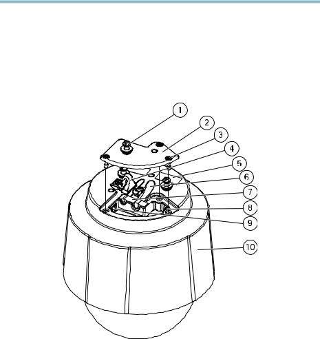
Hardware Overview
1Unit holder (3x)
2Camera base lid
3Camera base lid screw T20 (3x)
4Hook for safety wire
5Part number (P/N) & Serial number (S/N)
6Cable track (2x)
7Foam gasket
8Network connector (PoE+)
9Multi-connector
10Top cover
10
AXIS Q60 Series
Camera Unit
1SD card slot (SDHC)
2Status LED indicator
3Control button
4Power button
Dome Cover
1Dome bracket screw T20 (4x)
2Dome bracket
3Dome cover
4Dome ring screw T20 (4x)
5Dome ring
11
AXIS Q60 Series
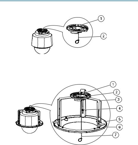
Hard Ceiling Mount
1Mounting plate
2Safety wire
Drop Ceiling Mount
1Mounting plate
2Mounting plate screw T20 (3x)
3Bracket arm
4Bracket arm screw T20 (3x) and washer (3x)
5Bracket ring
6Trim ring
7Safety wire
12
AXIS Q60 Series
LED Indicators
LED |
Color |
Indication |
|
|
|
Status |
Unlit |
Connection and normal operation |
|
|
|
|
Amber |
Steady during startup. Flashes during firmware upgrade. |
|
|
|
|
Amber/red |
Flashes amber/red if network connection is unavailable |
|
|
or lost. |
|
|
|
|
Red |
Flashes red for firmware upgrade failure. |
|
|
|
|
Green |
Shows steady green for 10 seconds for normal operation |
|
|
after restart. |
|
|
|
Midspan LED Indicators
LED |
Color |
Indication |
|
|
|
Port |
Unlit |
No camera connected. |
|
|
|
|
Green |
Steady when camera connected, normal operation. |
|
|
|
|
Green, flashing |
Slow flash when overcurrent or short circuit condition |
|
|
on the port. |
|
|
|
|
Green, flashing |
Fast flash when input voltage is out of range or other |
|
|
internal error. |
|
|
|
AC |
Green |
Steady when AC power input connected. |
|
|
|
Connectors
Network connector - RJ45 Ethernet connector. Supports Power over Ethernet Plus (PoE+) IEEE 802.3at. Use the supplied midspan.
NOTICE
The product shall be connected using a shielded network cable (STP). All cables connecting the product to the midspan shall be shielded (STP) and intended for their specific use. Make sure that the midspan is properly grounded. For information about regulatory requirements, see Regulatory Information, on page 2.
SD card slot - A standard or high-capacity SD card (not included) can be used for local recording with removable storage.
13

AXIS Q60 Series
NOTICE
To prevent corruption of recordings, the SD card should be unmounted before removal. To unmount, go to Setup > System Options > Storage > SD Card and click Unmount.
Control button - The control button is used for:
•Resetting the product to factory default settings. See page 26.
•Connecting to an AXIS Video Hosting System service or AXIS Internet Dynamic DNS Service. For more information about these services, see the User Manual.
Power button - Press the power button to temporarily power the product when the dome cover is removed. The power button is also used with the control button to reset the camera to factory default settings. See page 26.
Multi-connector - Terminal connector for connecting external equipment:
•Audio equipment
•Input/Output (I/O) devices
•AC/DC power supply
When connecting external equipment, a multi-connector cable (available from Axis) is required in order to maintain the product’s IP rating. For more information, see Multi-Connector Cable (sold separately), on page 14.
Multi-Connector Cable (sold separately)
When connecting external equipment to the Axis product, a multi-connector cable (available from Axis) is required in order to maintain the product’s IP rating. The multi-connector cable can be purchased from your Axis reseller.
Connect the multi-connector cable to the product’s multi-connector. To locate the multi-connector, see Hardware Overview, on page 10. The cable provides the following connectors:
Power connector - 3-pin terminal block used for power input. See image below. Use a limited power source (LPS) with either a rated output power limited to £100 W or a rated output current limited to £5 A.
Audio in (pink) - 3.5 mm input for a mono microphone, or a line-in mono signal (left channel is used from a stereo signal).
Audio out (green) - 3.5 mm output for audio (line level) that can be connected to a public address (PA) system or an active speaker with a built-in amplifier. A stereo connector must be used for the audio out.
I/O terminal connector - Use with external devices in combination with, for example, tampering alarms, motion detection, event triggering, time lapse recording and alarm notifications. In addition to ground and auxiliary power, the I/O terminal connector provides the interface to:
14

AXIS Q60 Series
•Digital output — For connecting external devices such as relays and LEDs. Connected devices can be activated by the VAPIX® Application Programming Interface, output buttons on the Live View page or by an Action Rule. The output will show as active (shown under System Options > Port & Devices > Port Status) if the alarm device is activated.
•Digital input — An alarm input for connecting devices that can toggle between an open and closed circuit, for example: PIRs, door/window contacts, glass break detectors, etc. When a signal is received the state changes and the input becomes active (shown under System Options > Port & Devices > Port Status).
Function |
Pin |
Notes |
Specifications |
|
|
|
|
GND |
1 |
Ground |
|
|
|
|
|
3.3 V DC |
2 |
Can be used to power auxiliary equipment. |
Max load: |
Power |
|
Note: This pin can only be used as power |
250 mA |
|
|
out. |
|
|
|
|
|
Configurable |
3–6 |
Digital input — Connect to GND to |
0 to +40 V DC |
(Input or |
|
activate, or leave floating (unconnected) |
|
Output) |
|
to deactivate. |
|
|
|
|
|
|
|
Digital output — Internal connection |
Max load: |
|
|
to ground when activated, floating |
100 mA |
|
|
(unconnected) when deactivated. If used |
Max voltage: |
|
|
with an external relay, a diode must be |
|
|
|
+40 V DC |
|
|
|
connected in parallel with the load, for |
|
|
|
|
|
|
|
protection against voltage transients. |
|
|
|
|
|
15

AXIS Q60 Series
Connection diagram
AI/O configured as input
BI/O configured as output
I/O connector |
DC power input |
AC power input |
|||||||||||||||||||||||||||||||||||||||||||||||||||||||||||
|
|
|
|
|
|
|
|
|
|
|
|
|
|
|
|
|
|
|
|
|
|
|
|
|
|
|
|
|
|
|
|
|
|
|
|
|
|
|
|
|
|
|
|
|
|
|
|
|
|
|
|
|
|
|
|
|
|
|
|
|
|
|
|
|
|
|
|
|
|
|
|
|
|
|
|
|
|
|
|
|
|
|
|
|
|
|
|
|
|
|
|
|
|
|
|
|
|
|
|
|
|
|
|
|
|
|
|
|
|
|
|
|
|
|
|
|
|
|
|
|
|
|
|
|
|
|
|
|
|
|
|
|
|
|
|
|
|
|
|
|
|
|
|
|
|
|
|
|
|
|
|
|
|
|
|
|
|
|
|
|
|
|
|
|
|
|
|
|
|
|
|
|
|
|
|
|
|
|
|
|
|
|
|
|
|
|
|
|
|
|
|
|
|
|
|
|
|
|
|
|
|
|
|
|
|
|
|
|
|
|
|
|
|
|
|
|
|
|
|
|
|
|
|
|
|
|
|
|
|
|
|
|
|
|
|
|
|
|
|
|
|
|
|
|
|
|
|
|
|
|
|
|
|
|
|
|
|
|
|
|
|
|
|
|
|
|
|
|
|
|
|
|
|
|
|
|
|
|
|
|
|
|
|
|
|
|
|
|
|
|
|
|
|
|
|
|
|
|
|
|
|
|
|
|
|
|
|
|
|
|
|
|
|
|
|
|
|
|
|
|
|
|
|
|
|
|
|
|
|
|
|
|
|
|
|
|
|
|
|
|
|
|
|
|
|
|
|
|
|
|
|
|
|
|
|
|
|
|
|
|
|
|
|
|
|
|
|
|
|
|
|
|
|
|
|
|
|
|
|
|
|
|
|
|
|
|
|
|
|
|
|
|
|
|
|
|
|
|
|
|
|
|
|
|
|
|
|
|
|
|
|
|
|
|
|
|
|
|
|
|
|
|
|
|
|
|
|
|
|
|
|
|
|
16

AXIS Q60 Series
Specifications
Operating Conditions
The Axis product is intended for indoor use.
Product |
Classification |
Temperature |
Humidity |
|
|
|
|
|
|
AXIS Q6032 |
IEC 60721-4-3 |
0 °C to 50 °C |
10-85% RH (non-condensing) |
|
|
Class 3K3, 3M3 |
(32 °F to 122 °F) |
|
|
AXIS Q6034 |
15-85% RH (non-condensing) |
|||
IEC 60529 IP52 |
|
|||
AXIS Q6035 |
|
|
20-85% RH (non-condensing) |
|
|
|
|
|
Power Consumption
NOTICE
Use a limited power source (LPS) with either a rated output power limited to £100 W or a rated output current limited to £5 A.
Product |
PoE+ |
DC |
AC |
|
|
|
|
AXIS Q6032 |
21 W |
24–34 V DC, max. 19.1 W |
20–24 V AC, max. 26.5 VA |
|
|
|
|
AXIS Q6034 |
21 W |
24–34 V DC, max. 19.2 W |
20–24 V AC, max. 26.7 VA |
|
|
|
|
AXIS Q6035 |
23 W |
24–34 V DC, max. 20 W |
20–24 V AC, max. 30 VA |
|
|
|
|
Install the Hardware
NOTICE
•(AXIS Q6034) Due to local regulations or the environmental and electrical conditions in which the product is to be used, a shielded network cable (STP) may be appropriate or required. Any network cables that are routed outdoors or in demanding electrical environments shall be shielded (STP) and intended for their specific use. Make sure that the midspan is properly grounded. For information about regulatory requirements, see
Regulatory Information, on page 2.
•(AXIS Q6032/Q6035) The product shall be connected using a shielded network cable (STP). All cables connecting the product to the midspan shall be shielded (STP) and intended for their specific use. Make sure that the midspan is properly grounded. For information about regulatory requirements, see Regulatory Information, on page 2.
•Be careful not to scratch, damage or leave fingerprints on the dome cover because this could decrease image quality. If possible, keep the protective plastic on the dome cover until the installation is complete.
17

AXIS Q60 Series
The Axis product can be installed with the cables routed through or along the wall or ceiling.
Read all the instructions before installing the product. Some installation steps would benefit from being completed together because they require removal of the dome cover.
•The product is supplied with a clear transparent dome cover (premounted) and a smoked transparent dome cover. To replace the dome cover, see page 18.
•A standard or high capacity SD card (not included) can be used to store recordings locally in the product. To install an SD card, see page 18.
•To install the product using the hard ceiling mount, see page 19.
•To install the product using the drop ceiling mount, see page 20.
•To install the product using a compatible bracket from AXIS T91A Mounting Accessories (sold separately), see page 23.
•To install the supplied midspan, see page 25.
Replace the Dome Cover
Replacing the dome cover is only necessary if you want to use the smoked transparent dome cover or if the dome cover is scratched or damaged.
1.Loosen the dome ring screws and remove the dome cover.
2.Remove the dome bracket screws and remove the dome bracket and the dome cover from the dome ring.
3.Attach the dome bracket and the dome cover to the dome ring and tighten the screws.
4.To install an SD card (not included), see Install an SD Card, on page 18.
5.Attach the dome cover to the top cover and tighten the screws (torque 1.5 Nm).
Install an SD Card
It is optional to install a standard or high capacity SD card (not included), which can be used for local recording with removable storage.
1.Loosen the dome ring screws and remove the dome cover.
2.Insert an SD card (not included) into the SD card slot.
3.Attach the dome cover to the top cover and tighten the screws (torque 1.5 Nm).
NOTICE
To prevent corruption of recordings, the SD card should be unmounted before it is ejected. To unmount, go to Setup > System Options > Storage > SD Card and click Unmount.
18

AXIS Q60 Series
Hard Ceiling Mount
1.Prepare the ceiling for installation of the mounting plate. The supplied drill template can be used to position the holes. Make sure to use drill bits, screws and plugs that are appropriate for the material.
2.Install the mounting plate. The arrow on the mounting plate will align with the logotype on the camera.
1Mounting plate
2Safety wire
3.Loosen the camera base lid screws and remove the camera base lid.
4.Secure the camera using the supplied safety wire.
5.Route and connect the network cable and the multi-connector cable (sold separately), if applicable, to the camera.
NOTICE
•Be careful not to damage the cables when connecting them.
•Make sure that the foam gasket holes are aligned with the cable tracks and, if applicable, remove the cut-out piece for the multi-connector cable from the foam gasket.
1Cable holders
2Multi-connector cable (sold separately)
3Network cable (not included)
19
AXIS Q60 Series
6.Turn the cable holders to keep the cables in place.
7.Put the camera base lid back in its original position and tighten the screws (torque 1.5 Nm).
8.Slide the unit holders on the network camera into the slots in the mounting plate and rotate the camera unit.
9.Install the supplied midspan. See page 25.
Drop Ceiling Mount
 WARNING
The combined weight of the camera and ceiling mount is approximately 3200 g (7.1 lb.). Make sure that the ceiling material is strong enough to support this weight.
NOTICE
The ceiling tile should be 5–60 mm (0.2–2.4 in.) thick.
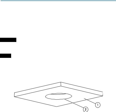
1.Remove the ceiling tile in which the drop ceiling mount is to be fitted.
2.Cut a hole in the ceiling tile for the drop ceiling mount. Use the supplied template to mark the position and cut around the template.
1Ceiling tile
2Hole diameter 225 mm (8.9 in.)
3.Assemble the ceiling bracket and attach it to the ceiling tile. Make sure the arrows on the mounting plate and the ceiling bracket are pointing in the same direction for the logotypes on the camera and the trim ring to align.
4.Tighten the bracket arm screws.
5.Loosen the camera base lid screws and remove the camera base lid.
6.Route and connect the network cable and the multi-connector cable (sold separately), if applicable, to the camera.
20
AXIS Q60 Series
NOTICE
•Be careful not to damage the cables when connecting them.
•Make sure that the foam gasket holes are aligned with the cable tracks and, if applicable, remove the cut-out piece for the multi-connector cable from the foam gasket.
1Cable holders
2Multi-connector cable (sold separately)
3Network cable (not included)
7.Turn the cable holders to keep the cables in place.
8.Put the camera base lid back in its original position and tighten the screws (torque 1.5 Nm).
9.Secure the camera using the supplied safety wire.
21
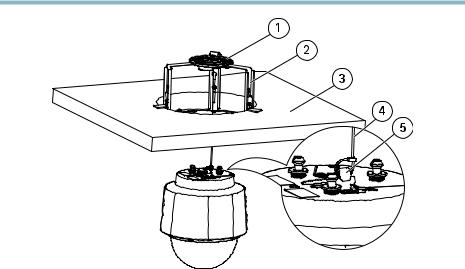
AXIS Q60 Series
1Mounting plate
2Ceiling bracket
3Ceiling tile
4Safety wire
5Hook for safety wire
10.Slide the unit holders on the network camera into the slots in the mounting plate and rotate the camera unit.
11.Install the supplied midspan. See page 25.
12.Install the ceiling tile with the camera mounted on it.
13.Put the trim ring on the ceiling bracket and tighten the screws.
22

AXIS Q60 Series
1Trim ring
2Trim ring screw T20 (4x)
Bracket Mount (sold separately)
1.Install the selected bracket according to the instructions supplied with the bracket. If drilling is required, make sure to use drill bits, screws and plugs that are appropriate for the material.
2.Loosen the camera base lid screws and remove the camera base lid.
3.Route the network cable and the multi-connector cable, if applicable, through the holes in the mounting bracket.
4.Secure the camera using the supplied safety wire.
23

AXIS Q60 Series
1Screw T30 (3x)
2Slot for unit holder (3x)
3Safety wire
4Wall bracket (mounting example)
5.Route and connect the network cable and the multi-connector cable (sold separately), if applicable, to the camera.
NOTICE
•Be careful not to damage the cables when connecting them.
•Make sure that the foam gasket holes are aligned with the cable tracks and, if applicable, remove the cut-out piece for the multi-connector cable from the foam gasket.
1Cable holders
2Multi-connector cable (sold separately)
3Network cable (not included)
24
AXIS Q60 Series
6.Turn the cable holders to keep the cables in place.
7.Put the camera base lid back in its original position and tighten the screws (torque 1.5 Nm).
8.Slide the unit holders on the network camera into the slots in the mounting plate and rotate the camera unit.
9.Secure the network camera to the mounting bracket by tightening the screws.
10.Install the supplied midspan. See page 25.
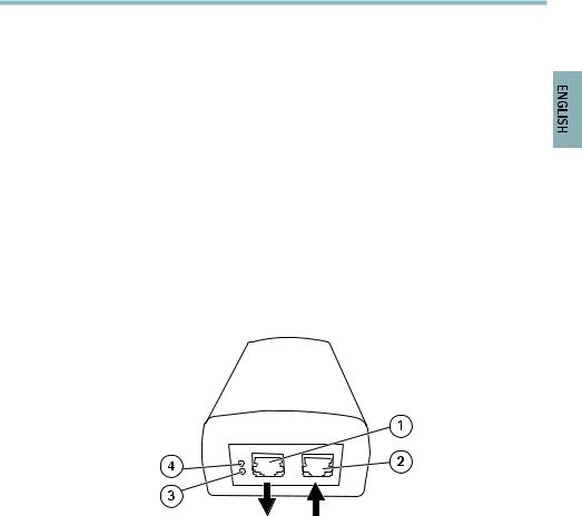
Install the Midspan
The supplied midspan enables Axis network video products with high power consumption to receive data and power over the same network cable.
1.Connect the midspan (data in) to the network switch using a network cable.
2.Connect the midspan (data and power out) to the camera using the network cable that has been connected to the camera.
3.Connect the midspan to a grounded (earthed) mains power outlet (100–240 V AC) using the supplied power cable.
1Data and power out (connect to Axis product)
2Data in (connect to network)
3AC input LED indicator
4Port LED indicator
4.Make sure that the LEDs on the midspan indicate the correct conditions. See Midspan LED Indicators, on page 13.
25

AXIS Q60 Series
Access the Product
Use the tools provided on the Installation and Management Software CD to assign an IP address, set the password and access the video stream. This information is also available from the support pages on www.axis.com/techsup/
Reset to Factory Default Settings
Important
Reset to factory default should be used with caution. A reset to factory default will reset all settings, including the IP address, to the factory default values.
To reset the product to the factory default settings:
1.Press and hold the control button and the power button for about 15 seconds until the status LED indicator flashes amber. See Hardware Overview, on page 10.
2.Release the control button but continue to hold down the power button until the status LED indicator turns green.
3.Release the power button and assemble the product.
4.The process is now complete. The product has been reset to the factory default settings. If no DHCP server is available on the network, the default IP address is 192.168.0.90
5.Use the tools provided on the Installation and Management Software CD to assign an IP address, set the password and access the video stream. This information is also available from the support pages on www.axis.com/techsup/
It is also possible to reset parameters to factory default via the web interface. Go to Setup > System Options > Maintenance.
Further Information
The User Manual is available at www.axis.com
Visit www.axis.com/techsup/ to check if there is updated firmware available for your network product. To see the currently installed firmware version, go to Setup > About.
Visit Axis learning center www.axis.com/academy/ for useful trainings, webinars, tutorials and guides.
Warranty Information
For information about Axis’ product warranty and thereto related information, see www.axis.com/warranty/
26

AXIS Q60 Series
Informations sur la sécurité
Lisez attentivement ce guide d'installation avant d'installer l'appareil. Conservez le Guide d'installation pour référence ultérieure.
Niveaux de risques
DANGER |
|
|
Indique une situation dangereuse qui, si elle n'est pas évitée, |
|
|
|
|
|
entraînera le décès ou les blessures graves. |
|
|
|
|
|
AVERTISSEMENT |
Indique une situation dangereuse qui, si elle n'est pas évitée, |
|||
|
|
|
|
pourrait entraîner le décès ou les blessures graves. |
|
|
|
||
ATTENTION |
|
Indique une situation dangereuse qui, si elle n'est pas évitée, |
||
|
|
|
|
pourrait entraîner les blessures légères ou modérées. |
|
|
|||
AVIS |
|
Indique une situation qui, si elle n'est pas évitée, pourrait entraîner |
||
|
|
|
|
des dommages à l'appareil. |
Autres niveaux de message
Important |
Indique les informations importantes, nécessaires pour assurer le |
|
|
|
bon fonctionnement de l'appareil. |
|
|
|
Note |
|
Indique les informations utiles qui permettront d'obtenir le plein |
|
|
potentiel de l'appareil. |
27

AXIS Q60 Series
Consignes de sécurité
 AVERTISSEMENT
• Le produit Axis doit être installé par un professionnel formé.
AVIS
•Le produit Axis doit être utilisé conformément aux lois et dispositions locales en vigueur.
•Pour utiliser le produit Axis à l'extérieur, ou dans des environnements similaires, il doit être installé dans un boîtier d'extérieur homologué.
•Rangez le produit Axis dans un environnement sec et aéré.
•Évitez d'exposer ce produit aux vibrations, au chocs et à une pression élevée.
•N'installez pas l'appareil sur des supports, des surfaces ou des murs instables ou qui vibrent.
•Utilisez uniquement des outils recommandés pour l'installation de l'appareil Axis. Une force excessive pourrait endommager l'appareil.
•N'utilisez pas de produits chimiques, d'agents caustiques ou de nettoyants en aérosol. Utilisez un chiffon humide pour le nettoyage.
•Utilisez uniquement des accessoires conformes aux caractéristiques techniques de l'appareil. Ils peuvent être achetés auprès d'Axis ou d'un tiers.
•Utilisez uniquement les pièces de rechange fournies ou recommandées par Axis.
•N'essayez pas de réparer l'appareil par vous-même. Contactez l'assistance technique d'Axis ou votre revendeur Axis pour les problèmes d'entretien
Transport
AVIS
•Lors du transport du produit Axis, utilisez l'emballage d'origine ou l'équivalent pour éviter d'endommager le produit.
Batterie
Le produit Axis utilise une batterie au lithium CR2032 3,0 V comme alimentation de son horloge en temps réel interne (RTC). Dans des conditions normales, cette batterie a une durée de vie minimale de cinq ans.
Une batterie faible affecte sur le fonctionnement du RTC, entraînant sa réinitialisation à chaque mise sous tension. Un message de journal apparaît lorsque la batterie doit être remplacée.
La batterie doit être remplacée uniquement en cas de besoin, et pour le faire, contactez l'assistance technique d'Axis à l'adresse www.axis.com/techsup/ pour obtenir de l'aide.
28

AXIS Q60 Series
 AVERTISSEMENT
•Risque d'explosion si la batterie est remplacée de façon incorrecte.
•Remplacez-la uniquement par une batterie identique ou une batterie recommandée par Axis.
•Mettez au rébut les piles usagées conformément aux réglementations locales ou aux instructions du fabricant de la batterie.
Couvercle du dôme
AVIS
•Veillez à ne pas rayer, endommager ou laisser d'empreintes sur le couvercle du dôme car cela pourrait altérer la qualité d'image. Si possible, gardez le plastique de protection sur le couvercle du dôme jusqu'à la fin de l'installation.
•Ne nettoyez pas un couverclu de dôme qui semble propre à l'œil nu et ne polissez jamais la surface. Un nettoyage excessif pourrait endommager la surface.
•Pour le nettoyage général du couvercle du dôme, il est recommandé d'utiliser un produit non abrasif, un savon neutre sans solvant ou un détergent avec de l'eau et un chiffon doux. Rincez bien à l'eau tiède propre. Sécher avec un chiffon doux pour éviter les tâches d'eau.
•N'utilisez jamais de détergents agressifs, de l'essence, du benzène ou de l'acétone, etc. et évitez de nettoyer le couvercle du dôme au contact de la lumière directe du soleil ou à des températures élevées.
29
30
 Loading...