


AXIS T98A-VE Media Converter Cabinet A Series
Installation Guide
Legal Considerations
Video and audio surveillance can be regulated by laws that vary from country to country. Check the laws in your local region before using this product for surveillance purposes.
Liability
Every care has been taken in the preparation of this document. Please inform your local Axis office of any inaccuracies or omissions. Axis Communications AB cannot be held responsible for any technical or typographical errors and reserves the right to make changes to the product and manuals without prior notice. Axis Communications AB makes no warranty of any kind with regard to the material contained within this document, including, but not limited to, the implied warranties of merchantability and fitness for a particular purpose. Axis Communications AB shall not be liable nor responsible for incidental or consequential damages in connection with the furnishing, performance or use of this material. This product is only to be used for its intended purpose.
Intellectual Property Rights
Axis AB has intellectual property rights relating to technology embodied in the product described in this document. In particular, and without limitation, these intellectual property rights may include one or more of the patents listed at www.axis.com/patent.htm and one or more additional patents or pending patent applications in the US and other countries.
Equipment Modifications
This equipment must be installed and used in strict accordance with the instructions given in the user documentation. This equipment contains no
user-serviceable components. Unauthorized equipment changes or modifications will invalidate all applicable regulatory certifications and approvals.
Trademark Acknowledgments
AXIS COMMUNICATIONS, AXIS, ETRAX, ARTPEC and VAPIX are registered trademarks or trademark applications of Axis AB in various jurisdictions. All other company names and products are trademarks or registered trademarks of their respective companies.
Regulatory Information
Europe

 This product complies with the applicable CE marking directives and harmonized standards:
•Electromagnetic Compatibility (EMC) Directive 2004/108/EC. See Electromagnetic Compatibility (EMC) on page 2.
•Low Voltage (LVD) Directive 2006/95/EC. See Safety on page 2.
•Restrictions of Hazardous Substances (RoHS) Directive
2011/65/EU. See Disposal and Recycling on page 3. A copy of the original declaration of conformity may be obtained from Axis Communications AB. See Contact Information on page 3.
Electromagnetic Compatibility (EMC)
This equipment has been designed and tested to fulfill applicable standards for:
•Radio frequency emission when installed according to the instructions and used in its intended environment.
•Immunity to electrical and electromagnetic phenomena when installed according to the instructions and used in its intended environment.
USA
This equipment has been tested using a shielded network cable (STP) and found to comply with the limits for a Class A digital device, pursuant to part 15 of the FCC Rules. These limits are designed to provide reasonable protection against harmful interference when the equipment is operated in a commercial environment. This equipment generates, uses, and can radiate radio frequency energy and, if not installed and used in accordance with the instruction manual, may cause harmful interference to radio communications. Operation of this equipment in
a residential area is likely to cause harmful interference in which case the user will be required to correct the interference at his own expense.
The product shall be connected using a shielded network cable (STP) that is properly grounded.
Canada
This digital apparatus complies with CAN ICES-3 (Class A). The product shall be connected using a shielded network cable (STP) that is properly grounded.
Cet appareil numérique est conforme à la norme NMB ICES-3 (classe A). Le produit doit être connecté à
l'aide d'un câble réseau blindé (STP) qui est correctement mis à la terre.
Europe
This digital equipment fulfills the requirements for RF emission according to the Class A limit of EN 55022. The product shall be connected using a shielded network cable (STP) that is properly grounded. Notice! This is a Class A product. In a domestic environment this product may cause RF interference, in which case the user may be required
to take adequate measures.
This product fulfills the requirements for emission and immunity according to EN 50121-4 and IEC 62236-4 railway applications.
This product fulfills the requirements for immunity according to EN 61000-6-1 residential, commercial and light-industrial environments.
This product fulfills the requirements for immunity according to EN 61000-6-2 industrial environments.
This product fulfills the requirements for immunity according to EN 55024 office and commercial environments
Australia/New Zealand
This digital equipment fulfills the requirements for RF emission according to the Class A limit of AS/NZS CISPR 22. The product shall be connected using a shielded network cable (STP) that is properly grounded. Notice! This is a Class A product. In a domestic environment this product may cause RF interference, in which case the user may be required to take adequate measures.
Japan
A (STP)
Safety
This product complies with IEC/EN/UL 60950-1 and IEC/EN/UL 60950-22, Safety of Information Technology Equipment. The product shall be grounded either through a shielded network cable (STP) or other appropriate method.
The power supply used with this product shall fulfill the requirements for Safety Extra Low Voltage

(SELV) and Limited Power Source (LPS) according to IEC/EN/UL 60950-1.
Disposal and Recycling
When this product has reached the end of its useful life, dispose of it according to local laws and regulations. For information about your nearest designated collection point, contact your local authority responsible for waste disposal. In accordance with local legislation, penalties may be applicable for incorrect disposal of this waste.
Europe
 This symbol means that the product shall not be disposed of together with household or commercial waste. Directive 2012/19/EU on waste electrical and electronic equipment (WEEE) is applicable in the European Union member states. To prevent potential harm to human health and the environment, the product must be disposed of in an approved and environmentally safe recycling process. For information about your nearest designated collection point, contact your local authority responsible for waste disposal. Businesses should contact the product supplier for information about how to dispose of this product correctly.
This product complies with the requirements of Directive 2011/65/EU on the restriction of the use of certain hazardous substances in electrical and electronic equipment (RoHS).
China
 This product complies with the requirements of the legislative act Administration on the Control of Pollution Caused by Electronic Information Products (ACPEIP).
Contact Information
Axis Communications AB Emdalavägen 14
223 69 Lund Sweden
Tel: +46 46 272 18 00 Fax: +46 46 13 61 30
www.axis.com
Support
Should you require any technical assistance, please contact your Axis reseller. If your questions cannot be answered immediately, your reseller will forward your queries through the appropriate channels to ensure a rapid response. If you are connected to the Internet, you can:
•download user documentation and software updates
•find answers to resolved problems in the FAQ database. Search by product, category, or phrase
•report problems to Axis support staff by logging in to your private support area
•chat with Axis support staff
•visit Axis Support at www.axis.com/techsup/
Learn More!
Visit Axis learning center www.axis.com/academy/ for useful trainings, webinars, tutorials and guides.

AXIS T98A-VE Media Converter Cabinet A Series
Safety Information
Read through this Installation Guide carefully before installing the product. Keep the Installation Guide for future reference.
Hazard Levels
DANGER |
|
|
Indicates a hazardous situation which, if not avoided, will result in |
|
|
|
|
|
death or serious injury. |
|
|
|
|
|
WARNING |
Indicates a hazardous situation which, if not avoided, could result |
|||
|
|
|
|
in death or serious injury. |
|
|
|
||
CAUTION |
|
Indicates a hazardous situation which, if not avoided, could result |
||
|
|
|
|
in minor or moderate injury. |
|
|
|||
NOTICE |
|
Indicates a situation which, if not avoided, could result in damage |
||
|
|
|
|
to property. |
Other Message Levels
Important |
Indicates significant information which is essential for the product |
|
|
|
to function correctly. |
|
|
|
Note |
|
Indicates useful information which helps in getting the most out |
|
|
of the product. |
5

AXIS T98A-VE Media Converter Cabinet A Series
Safety Instructions
 WARNING
• The Axis product shall be installed by a trained professional.
NOTICE
•The Axis product shall be used in compliance with local laws and regulations.
•Store the Axis product in a dry and ventilated environment.
•Avoid exposing the Axis product to shocks or heavy pressure.
•Do not install the product on unstable brackets, surfaces or walls.
•Use only applicable tools when installing the Axis product. Using excessive force with power tools could cause damage to the product.
•Use only accessories that comply with technical specification of the product. These can be provided by Axis or a third party.
•Use only spare parts provided by or recommended by Axis.
•Do not attempt to repair the product by yourself. Contact Axis support or your Axis reseller for service matters.
Transportation
NOTICE
•When transporting the Axis product, use the original packaging or equivalent to prevent damage to the product.
6

AXIS T98A-VE Media Converter Cabinet A Series
Installation Guide
This Installation Guide provides instructions for installing AXIS T98A Media Converter Cabinet A Series.
Installation Steps
1.Make sure the package contents, tools and other materials necessary for the installation are in order. See page 7.
2.Study the hardware overview. See page 8.
3.Study the specifications. See page 12.
4.Install the hardware. See page 13.
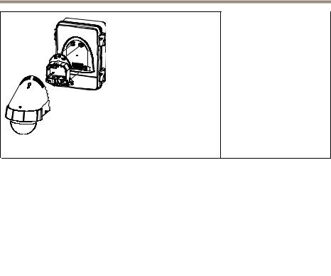
Package Contents
•Surveillance Cabinet
-AXIS T98A15-VE Media Converter Cabinet A
-AXIS T98A16-VE Media Converter Cabinet A
-AXIS T98A17-VE Media Converter Cabinet A
-AXIS T98A18-VE Media Converter Cabinet A
-AXIS T98A19-VE Media Converter Cabinet A
•Installation Guide (this document)
•Cable clamps
•Electrical safety cover
•Media Converter
•DIN clip for optional midspan (valid only for variants using midspan)
•Optional Accessories (see Technical Specifications)
7

AXIS T98A-VE Media Converter Cabinet A Series
Hardware Overview
1Cabinet door
2Power supply
3Cabinet base
4Hinges (2x left side, 2x right side)
5DIN rail
6Cable hole and gasket: M25 (3/4 in), M20 (1/2 in) (3x)
7Electrical safety cover
8Electrical safety kit
9Secure screws (2x)
10Hinge pins (2x)
11Slot for door switch
12Media converter
8

AXIS T98A-VE Media Converter Cabinet A Series
Mounting plate
1Mounting plate
2Hook
3Screw hole for wall mount ø6.55 mm (0.26 in) (6x)
4Screw hole for bracket mount ø8.55 mm (0.35 in) (4x)
5Knock-out M25 (3/4 in) (5x)
6Knock-out M25 (3/4 in) (8x)
7Knock-out M50 (1 1/2 in); M25 (3/4 in)
8Alignment indicator
9

AXIS T98A-VE Media Converter Cabinet A Series
AXIS T8604 Media Converter Switch
1Ground screw
2Power connector (DC input)
3Network connectors SFP
4Network connectors RJ45
5Network LED indicators
6Power LED indicator
Interface Overview
Included in all variants:
• Cable clamp (1x)
• Cable clamp (5x)
• Cable clamp (2x)
• Screw (6x)
• Screw (2x)
10
AXIS T98A-VE Media Converter Cabinet A Series
AXIS T98A15-VE Media
Converter Cabinet A
• Screw T30 (4x)
• Washer (4x)
• Cable gasket M20 (2x)
AXIS T98A16-VE Media
Converter Cabinet A
• Screw T20 (4x)
• Washer (4x)
• Cable gasket M20 (3x)
AXIS T98A17-VE Media
Converter Cabinet A
• Screw T30 (6x)
• Washer (6x)
• Cable gasket M20 (2x)
AXIS T98A18-VE Media
Converter Cabinet A
11
AXIS T98A-VE Media Converter Cabinet A Series
• Screw T30 (4x)
• Washer T20 (4x)
• Cable gasket M20 (2x)
AXIS T98A19-VE Media
Converter Cabinet A
Media Converter LED Indicators
LED |
Color |
Indication |
|
|
|
Power |
Unlit |
DC power unconnected or current protection engaged |
|
|
(power overload). |
|
|
|
|
Green |
DC power connected. |
|
|
|
Network (4x) |
Amber |
10 Mbit connection. Flashes during activity. |
|
|
|
|
Green |
100/1000 Mbit connection. Flashes during activity. |
|
|
|
Connectors and Buttons
For specifications and operating conditions, see page 12.
Network Connector
RJ45 Ethernet connector.
The unit can only use one Network interface, either an SFP module or RJ45 connector. SFP module has higher priority than the RJ45 connector.
Specifications
Operating Conditions
The Axis product is intended for outdoor use.
12

AXIS T98A-VE Media Converter Cabinet A Series
Product |
Temperature |
Humidity |
|
|
|
AXIS T98A-VE |
-40 °C to 65 °C |
10-100% RH (condensing) |
Media Converter |
(-40 °F to 149 °F) |
|
Cabinet A Series* |
|
|
|
|
|
* For variants using a midspan, see the technical specification for the current midspan.
Screw Torque Specification
Screw |
Torque |
|
|
|
|
Secure cabinet base to |
3.0 Nm ±0.2 |
2.21 lb-ft ±0.15 |
mounting plate |
|
|
|
|
|
Attach electrical safety cover |
0.8 Nm ±0.1 |
0.59 lb-ft ±0.07 |
to cabinet base |
|
|
|
|
|
Attach cabinet door to cabinet |
3.5 Nm ±0.2 |
2.58 lb-ft ±0.15 |
base |
|
|
|
|
|
Screws for attaching for |
0.8 Nm ±0.1 |
0.59 lb-ft ±0.07 |
example cable clamps and DIN |
|
|
rails inside the cabinet |
|
|
|
|
|
Attach network camera |
3.0 Nm ±0.2 |
2.21 lb-ft ±0.15 |
bracket to AXIS T98A16-VE |
|
|
cabinet door |
|
|
|
|
|
Attach network camera |
1.2 Nm ±0.2 |
0.89 lb-ft ±0.15 |
bracket to AXIS T98A17-VE |
|
|
cabinet door |
|
|
|
|
|
Attach network camera |
3.0 Nm ±0.2 |
2.21 lb-ft ±0.15 |
bracket to AXIS T98A18-VE |
|
|
cabinet door |
|
|
|
|
|
Attach network camera |
3.0 Nm ±0.2 |
2.21 lb-ft ±0.15 |
bracket to AXIS T98A19-VE |
|
|
cabinet door |
|
|
|
|
|
Install the Hardware
NOTICE
• To avoid condensation, do not assemble or disassemble the product during rain.
13
AXIS T98A-VE Media Converter Cabinet A Series
Note
•The hinges have a stop that locks the cabinet door at 105°.
•For easy installation, the cabinet door can be removed while installing the cabinet base.
Install the Mounting Plate
Note
•For cables routed from below, use the bottom knock-outs. For cables routed from behind, use the rear knock-outs.
1.Install the mounting plate according to the instructions supplied with the mounting plate. If drilling is required, make sure to use drill bits, screws, and plugs appropriate for the material.
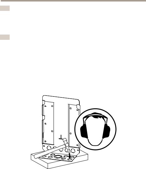
Remove the knock-outs in the following way:
2.Provide support for the mounting plate to make sure it remains flat and not bend when removing the knock-outs.
3.Strike the knock-out with a cross pein hammer until the knock-out pops out.
4. Mount the mounting plate on the wall or the selected bracket.
Install the Cabinet Base
1.Open drill-outs or cut-outs for cables in the cabinet base. Markings indicate where these cable holes can be drilled or cut out.
14

AXIS T98A-VE Media Converter Cabinet A Series
2.Install the media converter, see Install the Media Converter on page 16.
3.For variants using midspan: Install the midspan, see Install the Midspan on page 17.
4.Hang the cabinet base on the hooks of the mounting plate. Align the lower end of the cabinet with the alignment indicator for easy access while connecting the cables, see illustration below.
5.Connect the cables, see Connect the Cables on page 17.
6.Slide the cabinet base to the bottom position.
7.Secure the cabinet base to the mounting plate with the secure screws.
8.Move the hinge pins to the preferred side and hang the door on the hinges, see illustration below.
15

AXIS T98A-VE Media Converter Cabinet A Series
9.Install the network camera, see Install the Network Camera on page 21.
10.Fasten the cabinet door with the screws, see illustration below.
Install the Media Converter
See Hardware Overview on page 8 for locations of components.
Attach the media converter to the DIN rail in the cabinet.
16

AXIS T98A-VE Media Converter Cabinet A Series
Install the Midspan
Note
This instruction is valid only for variants using midspan.
1.Attach the included DIN clip to the midspan. See midspan Installation Guide.
2.Attach the midspan to the DIN rail.
1 |
Midspan |
2 |
DIN rail |
Connect the Cables
 DANGER
•The electrical connections and conduit installations shall be made by a certified electrician and in compliance with local regulations.
•Do not connect the power supply to the mains supply until the installation is complete.
17

AXIS T98A-VE Media Converter Cabinet A Series
NOTICE
•Cable gaskets shall be attached to all open cable holes in the cabinet base to maintain the product’s IP rating. If the holes are not sealed, water may seep into the cabinet and cause damage to the devices inside.
•Cables routed through M20 gaskets shall have a diameter of
3.5mm – 12.5 mm (0.14 in – 0.49 in).
•Cables routed through M25 gaskets shall have a diameter of
9.1mm – 12.5 mm (0.36 in – 0.49 in).
•Signal and power cables shall always be separated within the cabinet.
•Do not force the connector into the gasket.
•Use the cable to pierce a hole in the gasket. Do not use a knife or other sharp object that can damage the gasket.
To prepare a cable with a gasket, gently push the cable through the gasket and attach the appropriate connector.
Connect the Power Cables
NOTICE
•This is a Permanently connected equipment. A readily accessible disconnect device shall be incorporated externally to the equipment.
•The disconnect device provided external to the equipment shall be a two-pole disconnect device, disconnecting both the line and neutral conductor.
•It is recommended to use an external protective bonding wire with a minimum area of 6 mm2 (AWG 10) for indoor use and a minimum area of 10 mm2 (AWG 8) for outdoor use.
For connection diagram, see Connection Diagrams on page 25.
1. Remove the electrical safety cover.
18

AXIS T98A-VE Media Converter Cabinet A Series
2.Route the cables required for the installation through conduits (not included), cable gaskets and cable holes.
3.Attach the cable gaskets to the cable holes.
4.Connect the three incoming mains voltage cables and the external protective bonding wire as shown in the illustration.
1Line
2Neutral
3Ground cable
4External protective bonding wire
5.Attach the electrical safety cover using the supplied screws (torque 0.8 Nm ±0.1).
19

AXIS T98A-VE Media Converter Cabinet A Series
1Screw T20 (2x)
2Electrical safety cover
Connect the Media Converter Cables
Note
The media converter shall be connected using shielded network cables (STP) intended for their specific use. Make sure that the switch is properly grounded. See Electromagnetic Compatibility (EMC) for regulatory requirements.
1.Connect the ground cable to the ground screw.
2.Connect the network cables to the network connectors (RJ45, SFP) as required.
3.Connect the power cable to the power connector (DC input).
20
AXIS T98A-VE Media Converter Cabinet A Series
1Ground screw
2Power connector (DC input)
3Network cable
Connect the Midspan Cables
Note
This instruction is valid only for variants using midspan.
1.Connect a network cable between the midspan (data in) and the media converter.
2.Connect the premounted power cable to the power connector.
Install the Network Camera
The network camera is sold separately.
Note
When routing the cables, make sure the cable slack is long enough for the door to be fully opened.
21

AXIS T98A-VE Media Converter Cabinet A Series
See illustrations below for cable routing.
1.Route the network and power cables through the cabinet door and the camera bracket.
2.For variants using midspan: Connect the midspan (data and power out connection) to the camera using the network cable that has been connected to the camera.
3.Connect the power cable from the media converter cabinet to the camera.
4.Connect the network cable from the media converter to the camera.
5.If available, use the safety wire delivered with the mounting bracket to prevent the camera from falling.
6.Attach the camera to the cabinet door or, if applicable, to the camera bracket. See Screw Torque Specification on page 13.
AXIS T98A-VE Media Converter Cabinets
1Power cable to media converter
2Power cable to camera
3Network cable
22

AXIS T98A-VE Media Converter Cabinet A Series
Cabinet variant using optional midspan
1Power cable to media converter.
2Power cable to midspan
3Network cable to camera
4Network cable between midspan and media converter
Technical Specifications
Models |
AXIS T98A15-VE MEDIA CONVERTER CABINET A 120 V AC |
|
AXIS T98A16-VE MEDIA CONVERTER CABINET A 120 V AC |
|
AXIS T98A17-VE MEDIA CONVERTER CABINET A 120 V AC |
|
AXIS T98A18-VE MEDIA CONVERTER CABINET A 120 V AC |
|
AXIS T98A19-VE MEDIA CONVERTER CABINET A 120 V AC |
|
AXIS T98A15-VE MEDIA CONVERTER CABINET A 230 V AC |
|
AXIS T98A16-VE MEDIA CONVERTER CABINET A 230 V AC |
|
AXIS T98A17-VE MEDIA CONVERTER CABINET A 230 V AC |
|
AXIS T98A18-VE MEDIA CONVERTER CABINET A 230 V AC |
|
AXIS T98A19-VE MEDIA CONVERTER CABINET A 230 V AC |
|
|
Power |
Input (120 V AC): 90-175 V AC, max 4 A |
|
Input (230 V AC): 90-264 V AC, max 4 A |
|
Output AXIS T98A15-VE, AXIS T98A16-VE, AXIS T98A17-VE: |
|
12 V DC, 20 W |
|
|
23

AXIS T98A-VE Media Converter Cabinet A Series
|
Output AXIS T98A18-VE, AXIS T98A19-VE: equals input voltage, |
|
max 4 A |
|
|
Connectors |
2x RJ45 connectors (10/100 Mbps) |
|
2x SFP connectors (100/1000 Mbps) |
|
for SFP fiber optic modules or SFP to copper modules |
|
|
Casing |
Polycarbonate cabinet and stainless steel mounting plate |
|
Color: White NCS 1002-B and stainless steel |
|
|
Display and |
LED indicators |
indicators |
|
|
|
Environment |
Outdoor |
|
|
Approvals |
AXIS T98A-VE Series 230 V:: |
|
EN 55022 Class A |
|
EN 55024 |
|
EN 61000-3-2 |
|
EN 61000-3-3 |
|
EN 61000-6-1 |
|
EN 61000-6-2 |
|
C-Tick AS/NZS CISPR 22 Class A |
|
AXIS T98A-VE Series 120 V:: |
|
FCC Part 15 Subpart B Class A |
|
VCCI Class A |
|
ICES-003 Class A |
|
CISPR22 Class A |
|
AXIS T98A15-VE/T98A16-VE/T98A17-VE: |
|
IEC 60068-2-6 Vibration 4M4 |
|
IEC 60068-2-27 Shock 4M4 |
|
AXIS T98A18-VE/T98A19-VE: |
|
IEC 60068-2-6 Vibration 4M3 |
|
IEC 60068-2-27 Shock 4M3 |
|
Valid for all: |
|
EN 50121–4 |
|
IEC 62236-4 |
|
EN 50581 (RoHS) |
|
IEC/EN 60529 IP66 |
|
NEMA 250 Type 4X |
|
IEC/EN 62262 IK10 |
|
REACH |
|
WEEE |
|
CE |
|
|
Operating |
-40 °C to 65°C (-40 °F to 149 °F) |
conditions |
10–100% RH (condensing) |
|
For AXIS T98A18-VE Media Converter Cabinet operating conditions, |
|
see the technical specification for AXIS T8124 Midspan. |
|
|
24
AXIS T98A-VE Media Converter Cabinet A Series
Dimensions |
361 x 282 x 131 mm |
(HxWxL) |
(14.2 x 11.1 x 5.2 in) |
|
|
Weight |
4.4 kg |
|
(9.7 lb) |
|
|
Included |
Installation guide |
accessories |
Pre-mounted cable gaskets |
|
Pre-mounted DIN rails |
|
Cable clamps |
|
Electrical safety cover |
|
Pre-mounted MCB fuse |
|
Pre-mounted surge protection |
|
Pre-mounted 12 V DC power supply |
|
Media converter |
|
For variants using midspan: DIN clip for midspan |
|
|
Optional |
AXIS T98A Sunshield A |
accessories |
AXIS Door Switch |
|
AXIS T95A64 Bracket Corner |
|
AXIS T95A67 Bracket Pole |
|
AXIS Cabinet Lock A |
|
|
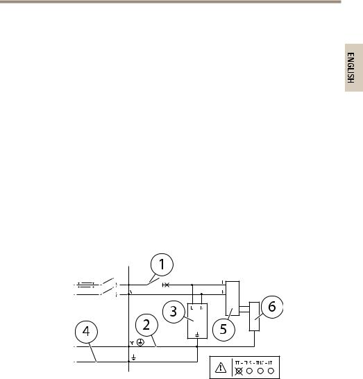
Connection Diagrams
1Circuit breaker/Fuse 4 A
2Incoming mains voltage
3Surge protector 230 V AC or 120 V AC
4External protective bonding wire
5Power supply unit
6Media converter
25

AXIS T98A-VE Media Converter Cabinet A Series
Further Information
Visit Axis learning center www.axis.com/academy for useful trainings, webinars, tutorials and guides.
Warranty Information
For information about Axis’ product warranty and thereto related information, see www.axis.com/warranty/
26

AXIS T98A-VE Media Converter Cabinet A Series
Informations sur la sécurité
Lisez attentivement ce guide d'installation avant d'installer l'appareil. Conservez le guide d'installation pour toute référence ultérieure.
Niveaux de risques
DANGER |
|
|
Indique une situation dangereuse qui, si elle n'est pas évitée, |
|
|
|
|
|
entraînera le décès ou des blessures graves. |
|
|
|
|
|
AVERTISSEMENT |
Indique une situation dangereuse qui, si elle n'est pas évitée, |
|||
|
|
|
|
pourrait entraîner le décès ou des blessures graves. |
|
|
|
||
ATTENTION |
|
Indique une situation dangereuse qui, si elle n'est pas évitée, |
||
|
|
|
|
pourrait entraîner des blessures légères ou modérées. |
|
|
|||
AVIS |
|
Indique une situation qui, si elle n'est pas évitée, pourrait |
||
|
|
|
|
endommager l'appareil. |
Autres niveaux de message
Important |
Indique les informations importantes, nécessaires pour assurer le |
|
|
|
bon fonctionnement de l'appareil. |
|
|
|
Note |
|
Indique les informations utiles qui permettront d'obtenir le |
|
|
fonctionnement optimal de l'appareil. |
27

AXIS T98A-VE Media Converter Cabinet A Series
Consignes de sécurité
 AVERTISSEMENT
• Le produit Axis doit être installé par un professionnel habilité.
AVIS
•Le produit Axis doit être utilisé conformément aux lois et règlementations locales en vigueur.
•Conserver ce produit Axis dans un environnement sec et ventilé.
•Ne pas exposer ce produit Axis aux chocs ou aux fortes pressions.
•Ne pas installer ce produit sur des supports, surfaces ou murs instables.
•Utiliser uniquement des outils recommandés pour l'installation de l'appareil Axis. L'application d'une force excessive sur l'appareil avec des outils puissants pourrait l'endommager.
•Utiliser uniquement des accessoires conformes aux caractéristiques techniques du produit. Ils peuvent être fournis par Axis ou un tiers.
•Utiliser uniquement les pièces de rechange fournies ou recommandées par Axis.
•Ne pas essayer de réparer ce produit par vous-même. Contacter l'assistance technique d'Axis ou votre revendeur Axis pour des problèmes liés à l'entretien.
Transport
AVIS
•Lors du transport du produit Axis, utilisez l'emballage d'origine ou un équivalent pour éviter d'endommager le produit.
28

AXIS T98A-VE Media Converter Cabinet A Series
Guide d'installation
Ce guide d'installation vous explique comment installer la série d'armoires A de convertisseur de média AXIS T98A.
Procédures d’installation
1.Assurez-vous que les outils et autres matériels nécessaires à l'installation sont inclus dans l'emballage. Cf. page 29.
2.Consultez la description du matériel. Cf. page 30.
3.Étudiez les caractéristiques. Cf. Caractéristiques techniques page 34.
4.Installez le matériel. Cf. page 35.
Contenu de l’emballage
•Armoire de surveillance
-Armoire A de convertisseur de média AXIS T98A15-VE
-Armoire A de convertisseur de média AXIS T98A16-VE
-Armoire A de convertisseur de média AXIS T98A17-VE
-Armoire A de convertisseur de média AXIS T98A18-VE
-Armoire A de convertisseur de média AXIS T98A19-VE
•Guide d’installation (ce document)
•Pinces de câbles
•Couvercle de sécurité électrique
•Convertisseur de média
•Clip DIN pour injecteur en option (valable uniquement pour les versions utilisant un injecteur)
•Accessoires en option (voir Caractéristiques techniques)
29

AXIS T98A-VE Media Converter Cabinet A Series
Aperçu du matériel
1Porte de l'armoire
2Alimentation
3Armoire
4Charnières (x2 côté gauche, x2 côté droit)
5Rail DIN
6Trou de câble et joint : M25 (3/4"), M20 (1/2") (x3)
7Couvercle de sécurité électrique
8Kit de sécurité électrique
9Vis de fixation (x2)
10Axes de charnières (x2)
11Trou pour interrupteur de porte
12Convertisseur de média
30
 Loading...