


 Loading...
INSTALLATION GUIDE
AXIS M7014 Video Encoder
AXIS M7010 Video Encoder
ESPAÑOL ITALIANO DEUTSCH AISÇFRAN ENGLISH

About this Document
This document includes instructions for installing the AXIS M7014/M7010 on your network. Previous experience of networking will be beneficial when installing the product.
Legal Considerations
Video and audio surveillance can be prohibited by laws that vary from country to country. Check the laws in your local region before using this product for surveillance purposes.
This product includes one (1) H.264 decoder license and one (1) AAC license. To purchase further licenses, contact your reseller.
Electromagnetic Compatibility (EMC)
This equipment generates, uses and can radiate radio frequency energy and, if not installed and used in accordance with the instructions, may cause harmful interference to radio communications. However, there is no guarantee that interference will not occur in a particular installation.
If this equipment does cause harmful interference to radio or television reception, which can be determined by turning the equipment off and on, the user is encouraged to try to correct the interference by one or more of the following measures: Re-orient or relocate the receiving antenna. Increase the separation between the equipment and receiver. Connect the equipment to an outlet on a different circuit to the receiver. Consult your dealer or an experienced radio/TV technician for help. Shielded (STP) network cables must be used with this unit to ensure compliance with EMC standards.
USA - This equipment has been tested and found to comply with the limits for a Class B computing device pursuant to Subpart B of Part 15 of FCC rules, which are designed to provide reasonable protection against such interference when operated in a commercial environment. Operation of this equipment in a residential area is likely to cause interference, in which case the user at his/her own expense will be required to take whatever measures may be required to correct the interference.
Canada - This Class B digital apparatus complies with Canadian ICES-003.
Europe - This digital equipment fulfills the requirements for radiated emission according to limit B of EN55022, and the requirements for immunity according to EN55024 residential and commercial industry.
Japan - This is a class B product based on the standard of the Voluntary Control Council for Interference from Information Technology Equipment (VCCI). If this is used near a radio or television receiver in a domestic environment, it may cause radio interference. Install and use the equipment according to the instruction manual.
Australia - This electronic device meets the requirements of the Radio communications (Electromagnetic Compatibility) Standard AS/NZS CISPR22.
Korea - 


Safety
This product is intended to receive power from an external power supply. This supply shall meet the requirements for Safety Extra Low Voltage and Limited Power Source according to EN 60 950-1.
Equipment Modifications
This equipment must be installed and used in strict accordance with the instructions given in the user documentation. This equipment contains no user-serviceable components. Unauthorized equipment changes or modifications will invalidate all applicable regulatory certifications and approvals.
Liability
Every care has been taken in the preparation of this document. Please inform your local Axis office of any inaccuracies or omissions. Axis Communications AB cannot be held responsible for any technical or typographical errors and reserves the right to make changes to the product and documentation without prior notice. Axis Communications AB makes no warranty of any kind with regard to the material contained within this document, including, but not limited to, the implied warranties of merchantability and fitness for a particular purpose. Axis Communications AB shall not be liable nor responsible for incidental or consequential damages in connection with the furnishing, performance or use of this material.
RoHS
This product complies with both the European RoHS directive, 2002/95/EC, and the Chinese RoHS regulations, ACPEIP.
WEEE Directive
The European Union has enacted a Directive 2002/96/EC on Waste Electrical and Electronic Equipment (WEEE Directive). This directive is applicable in the European Union member states.
The WEEE marking on this product (see right) or its documentation indicates that the product must not be disposed of together with household waste. To prevent possible harm to human health and/or the environment, the product must be disposed of in an approved and environmentally safe recycling process. For further information on how to dispose of this product correctly, contact the product supplier, or the local authority responsible for waste disposal in your area.
Business users should contact the product supplier for information on how to dispose of this product correctly. This product should not be mixed with other commercial waste. For more information, visit www.axis.com/techsup/commercial waste.
Support
Should you require any technical assistance, please contact your Axis reseller. If your questions cannot be answered immediately, your reseller will forward your queries through the appropriate channels to ensure a rapid response. If you are connected to the Internet, you can:
• download user documentation and firmware updates
• find answers to resolved problems in the FAQ database. Search by product, category, or phrases
• report problems to Axis support by logging in to your private support area.
The AXIS M7014/M7010 uses a 3.0V CR2032 Lithium battery, for more information please see page 3.
Safeguards
Please read through this Installation Guide carefully before installing the product. Keep the Installation Guide for further reference.
 CAUTION!
• When transporting the Axis product, use the original packaging or equivalent to prevent damage to the |
|
|
product. |
|
|
• Store the Axis product in a dry and ventilated environment. |
|
|
• Avoid exposing the Axis product to vibration, shocks or heavy pressure and do not install the camera on |
|
|
unstable brackets, unstable or vibrating surfaces or walls, since this could cause damage to the product. |
|
|
• Only use handtools when installing the Axis product, the use of electrical tools or excessive force could |
|
|
cause damage to the product. |
|
|
ENGLISH |
||
• Do not use chemicals, caustic agents, or aerosol cleaners. Use a damp cloth for cleaning. |
||
• Use only accessories that comply with technical specification of the product. These can be provided by Axis |
||
|
||
or a third party. |
|
|
• Use only spare parts provided by or recommended by Axis. |
|
|
• Do not attempt to repair the product by yourself, contact Axis or your Axis reseller for service matters. |
|
 IMPORTANT!
•This Axis product must be used in compliance with local laws and regulations.
Battery replacement
This Axis product uses a 3.0V CR2032 Lithium battery as the power supply for its internal real-time clock (RTC). Under normal conditions this battery will last for a minimum of 5 years. Low battery power affects the operation of the RTC, causing it to reset at every power-up. A log message will appear when the battery needs replacing. The battery should not be replaced unless required!
If the battery does need replacing, please contact www.axis.com/techsup for assistance.
•Danger of Explosion if battery is incorrectly replaced.
•Replace only with the same or equivalent battery, as recommended by the manufacturer.
•Dispose of used batteries according to the manufacturer's instructions.

AXIS M7014/M7010 Installation Guide |
Page 5 |
AXIS M7014/M7010 Video Encoder
Installation Guide
This installation guide provides instructions for installing the AXIS M7014/M7010 video encoder on your network. For all other aspects of using the product, please see the product’s User’s Manual, available on the CD included in this package, or from www.axis.com
Installation steps
Follow these steps to install the AXIS M7014/M7010 on your local network (LAN):
1.Check the package contents against the list below.
2.Hardware overview. See page 6.
3.Install the hardware. See page 7.
4.Assign an IP address. See page 9.
5.Set the password. See page 12.
 Package contents
Important!
This product must be used in compliance with local laws and regulations.
Item |
Models/variants/notes |
|
|
Axis video encoder models |
AXIS M7014 |
|
AXIS M7010 |
|
|
Power adapter models |
AXIS M7014: Type PS-K |
|
AXIS M7010: Type PS-P |
|
|
Mounting kit |
AXIS M7014 |
|
• 4 screws and 4 plugs to mount the encoder to a concrete wall |
|
AXIS M7010 |
|
• 8 screws (for mounting with brackets) |
|
• 2 mounting brackets |
|
• 4 M6x20 screws for mounting in rack |
|
AXIS M7014/M7010 |
|
• 4 Surface protection pads |
|
• Terminal block connectors (RS-485/RS-422: 2 x 2-pin connector |
|
for AXIS M7014; 8 x 2 pin connector for AXIS M7010, Power: 2- |
|
pin connector) |
|
|
CD |
AXIS Network Video Product CD, including product documentation, |
|
installation tools and other software |
|
|
Printed Materials |
AXIS M7014/M7010 Installation Guide (this document) |
|
Axis Warranty Document |
|
|
ENGLISH

Page 6 |
AXIS M7014/M7010 Installation Guide |
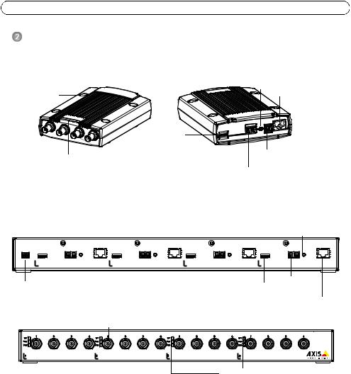
Hardware overview
|
AXIS M7014 |
|
Front view |
Rear view |
Control button |
|
|
|
Mounting holes |
|
Nework connector (PoE) |
|
microSD memory |
|
|
card slot |
|
LED indicators for |
Video input connectors |
Power connector |
|
||
|
|
|
power, status, network |
|
RS-485/RS-422 connector |
|
|
|
|
|
|
AXIS M7010 - rear view |
|
Control button |
||
|
|
|
PoE |
|
PoE |
|
PoE |
PoE |
PW R |
M EM O RY |
RS-485/422 |
M EM O RY |
RS-485/422 |
M EM O RY |
RS-485/422 |
M EM O RY |
RS-485/422 |
|
CARD |
|
CARD |
|
CARD |
|
CARD |
|
- + |
|
RX/TX TX |
|
RX/TX TX |
|
RX/TX TX |
|
RX/TX TX |
|
4 |
|
3 |
|
2 |
|
1 |
|
Power connector |
|
|
|
|
microSD card slot |
RS-485/RS-422 |
||
|
|
|
|
|
|
connector |
||
|
|
|
|
|
|
|
|
|
|
|
|
|
|
|
|
|
Network connector (P0E) |
|
|
|
Video input connectors |
AXIS M7010 - front view |
|
|
|
|
|
|
|
|||||||||
|
1 |
|
|
|
|
|
|
|
|
|
|
|
|
|
|
|
|
|
|
AXIS M7010 |
NE T |
|
2 |
3 |
4 |
NE T |
1 |
2 |
3 |
4 |
NE T |
1 |
2 |
3 |
4 |
NE T |
1 |
2 |
3 |
4 |
Video Encoder |
S TAT |
|
|
|
|
S TAT |
|
|
|
|
S TAT |
|
|
|
|
S TAT |
|
|
|
|
|
PWR |
PWR |
PWR |
PWR |
1 |
2 |
3 |
4 |
Group 1 |
Group 2 |
Group 3 |
Group 4 |
(4 video input connectors) |
|
LED indicators |
|
|
|
|
|
Dimensions
AXIS M7014 |
HxWxD = 37x109x172 |
|
Weight = 570g (1.27 lbs) |
|
|
AXIS M7010 |
HxWxD = 45x440x165 |
|
Weight = 2540g (5.82 lbs) |
|
|

AXIS M7014/M7010 Installation Guide |
Page 7 |
 Install the hardware
Important!
The casing of the AXIS M7014/M7010 is not approved for outdoor use - the product may only be installed in indoor environments.
Notes:
•The AXIS M7014/M7010 can simply be placed on a flat surface or mounted. See below for mounting instructions.
•Punch out the protective pads and stick them to the underside of the video encoder to prevent scratches on the surface where the video encoder is placed.
Mount the video encoder (AXIS M7014)
The video encoder is supplied with a mounting kit containing screws and plugs for mounting the video encoder to a concrete wall:
1.Place the video encoder against the wall, and mark the four mounting holes (see image on page 6).
2.Drill the four mounting holes.
3.Insert the provided wall plugs into the wall, and fasten the video encoder to the wall using the screws provided.
Mount the video encoder (AXIS M7010)
The video encoder is supplied with a mounting kit containing brackets and screws. The unit can be mounted in a rack or on a wall.
After removing the existing 4 screws, attach the mounting bracket to the video encoder at an angle suitable for installation in a standard 1U 19” rack, or on the wall.
|
AXIS M7010 in rack |
AXIS M7010 on wall |
|
Group 1 |
Group 2 |
Group 3 Group 4 |
|
|
|
|
Mounting bracket |
Bracket position for rack mount |
Bracket position for wall mount |
||
This side up |
|
|
|
|
|
Bracket |
This side up |
|
|
|
|
|
|
This side up |
|
ENGLISH

Page 8 |
AXIS M7014/M7010 Installation Guide |
Note: Each bracket must be attached to the appropriate side of the video encoder, and at an appropriate angle depending on whether it is mounted on the wall or in the rack.
Mounting on wall
1.Position the video encoder against the wall with the brackets attached, and mark the four mounting holes for each bracket (see image above).
2.Drill the four mounting holes.
3.Fasten the video encoder to the wall using appropriate screws.
Connect the cables
1.Connect the encoder to the network using shielded network cables. If using PoE see note below.
2.Connect the cameras to the video inputs.
3.If powering the unit with DC input, connect the supplied indoor power adapter or an external power supply. See note below.
4.Check that the indicator LEDs indicate the correct conditions. See the table on page 16 for further details.
Note: The unit can be powered using either the DC power input or PoE.
If powering the unit using DC power, connect the power supply to the power connector at the rear of the unit.
If powering the unit using PoE, connect a PoE network cable. For AXIS M7010, connect 4 PoE network cables (one for each group).

AXIS M7014/M7010 Installation Guide |
Page 9 |
 Assign an IP address
Most networks today have a DHCP server that automatically assigns IP addresses to connected devices. If your network does not have a DHCP server the AXIS M7014 will use 192.168.0.90 as the default IP address.
AXIS M7010 will use 4 different IP addresses for each group of 4 video input connectors. Numbers on the video encoder indicate each set of four. 192.168.0.90 is the default IP address for group 1, 192.168.0.91 for group 2, 192.168.0.92 for group 3, and 192.168.0.93 for group 4.
AXIS IP Utility and AXIS Camera Management are recommended methods for setting an IP address in Windows. These free applications are available on the Axis Network Video Product CD supplied with this product, or they can be downloaded from www.axis.com/techsup. Depending on the number of cameras you wish to install, use the method that suits you best.
Method |
Recommended for |
Operating system |
|
|
|
AXIS IP Utility |
Single video encoder |
Windows |
See page 10 |
Small installations |
|
|
|
|
AXIS Camera Management |
Multiple video encoders |
Windows 2000 |
See page 11 |
Large installations |
Windows XP Pro |
|
Installation on a different subnet |
Windows 2003 Server |
|
|
Windows Vista |
|
|
|
Notes:
•If assigning the IP address fails, check that there is no firewall blocking the operation.
•For other methods of assigning or discovering the IP address of the AXIS M7014/M7010, e.g. in other operating systems, see page 14.
ENGLISH

Page 10 |
AXIS M7014/M7010 Installation Guide |
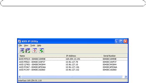
AXIS IP Utility - single camera/small installation
AXIS IP Utility automatically discovers and displays Axis devices on your network. The application can also be used to manually assign a static IP address.
Note that the computer running AXIS IP Utility must be on the same network segment (physical subnet) as the AXIS M7014/M7010.
Automatic discovery
1.Check that the AXIS M7014/M7010 is connected to the network and that power has been applied.
2.Start AXIS IP Utility.
3.When the AXIS M7014/M7010 appears in the window, double-click it to open its home page. AXIS M7010 appears in the window with one entry for each of its 4 groups of video inputs.
4.See page 12 for instructions on how to assign the password.
Set the IP address manually (optional)
1.Acquire an unused IP address on the same network segment as your computer.
2.Select AXIS M7014 or one of the AXIS M7010 in the list.
3.Click the button  Assign new IP address to selected device and enter the IP address.
4.Click the Assign button and follow the instructions.
5.Click the Home Page button to access the video encoder’s web pages.
6.See page 12 for instructions on how to set the password.
AXIS M7014/M7010 Installation Guide |
Page 11 |
AXIS Camera Management - multiple cameras/large installations
AXIS Camera Management can automatically find and set IP addresses, show connection status, and manage firmware upgrades for multiple Axis video products.
ENGLISH
Automatic discovery
1.Check that the encoder is connected to the network and that power has been applied.
2.Start AXIS Camera Management. When the video encoder appears in the window, double-click it to open the encoder’s home page.
AXIS M7010 appears in the window with one entry for each of its four groups of video input connectors.
3.See page 12 for instructions on how to set the password.
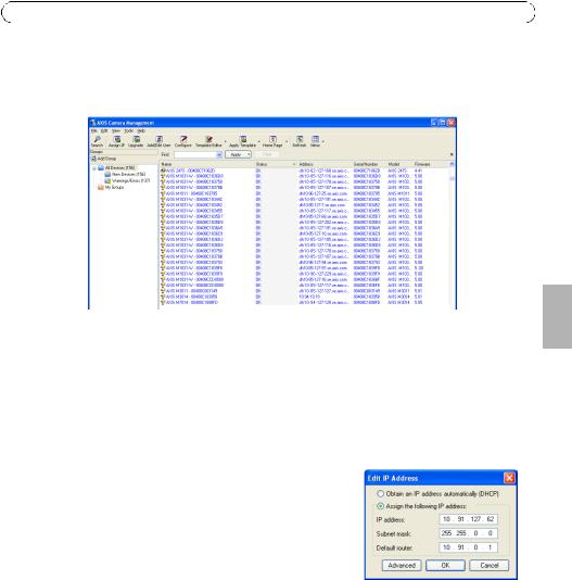
Assign an IP address in a single device
1.Select the video encoder in AXIS Camera Management and click the Assign IP button. 
2.Select Assign the following IP address and enter the IP address, the subnet mask and default router the device will use.
3.Click the OK button.
Assign IP addresses in multiple devices
AXIS Camera Management speeds up the process of assigning IP addresses to multiple devices, by suggesting IP addresses from a specified range.
1.Select the devices you wish to configure (different models can be selected) and click the Assign IP button. 
2.Select Assign the following IP address range and enter the range of IP addresses, the subnet mask and default router the devices will use.
3.Click the OK button.

Page 12 |
AXIS M7014/M7010 Installation Guide |
 Set the password
To gain access to the product, the password for the default administrator user root must be set. This is done in the ‘Configure Root Password’ dialog, which is displayed when the AXIS M7014/M7010 is accessed for the first time.
To prevent network eavesdropping when setting the root password, this can be done via an encrypted HTTPS connection, which requires an HTTPS certificate (see note below).
To set the password via a standard HTTP connection, enter it directly in the first dialog shown below.
To set the password via an encrypted HTTPS connection, follow these steps:
1.Click the Create self-signed certificate button.
2.Provide the requested information and click OK. The certificate is created and the password can now be set securely. All traffic to and from the AXIS M7014/M7010 is encrypted from this point on.
3.Enter a password and then re-enter it to confirm the spelling. Click OK. The password has now been configured.
To create an HTTPS connection, start by
 clicking this button.
To configure the password directly via an unencrypted connection, enter the password here.
4.To log in, enter the user name “root” in the dialog as requested.
Note: The default administrator user name root cannot be deleted.
5.Enter the password as set above, and click OK. If the password is lost, the AXIS M7014/M7010 must be reset to the factory default settings. See page 17.
6.If required, click Yes to install AMC (AXIS Media Control), which allows viewing of the video stream in Internet Explorer. You will need administrator rights on the computer to do this.

AXIS M7014/M7010 Installation Guide |
Page 13 |
7.The Live View page of the AXIS M7014/M7010 is displayed. The Setup link leads to menus which allow you to customize the encoder.
Setup - Provides all the tools for configuring the encoder to requirements.
Help - Displays  online help on all
aspects of using the encoder.
ENGLISH
Notes:
•HTTPS (Hypertext Transfer Protocol over SSL) is a protocol used to encrypt the traffic between web browsers and servers. The HTTPS certificate controls the encrypted exchange of information.
•The default administrator user root cannot be deleted.
•If the password for root is lost or forgotten, the AXIS M7014/M7010 must be reset to the factory default settings. See page 17.

Page 14 |
AXIS M7014/M7010 Installation Guide |
Other methods of setting the IP address
The table below shows other methods available for setting or discovering the IP address. All methods are enabled by default, and all can be disabled.
|
Use in operating |
Notes |
|
system |
|
|
|
|
UPnP™ |
Windows |
When enabled on your computer, the video encoder is |
|
|
automatically detected and added to “My Network Places.” |
|
|
|
Bonjour |
MAC OSX |
Applicable to browsers with support for Bonjour. Navigate to the |
|
(10.4 or later) |
Bonjour bookmark in your browser (e.g. Safari) and click on the |
|
|
link to access the video encoder’s web pages. |
|
|
|
AXIS Dynamic DNS |
All |
A free service from Axis that allows you to quickly and simply |
Service |
|
install your video encoder. Requires an Internet connection with |
|
|
no HTTP proxy. See www.axiscam.net for more information. |
ARP/Ping |
All |
See below. The command must be issued within 2 minutes of |
|
|
connecting power to the video encoder. |
View DHCP server |
All |
To view the admin pages for the network DHCP server, see the |
admin pages |
|
server’s own documentation. |
|
|
|
Set the IP address with ARP/Ping
1.Acquire a free static IP address on the same network segment your computer is connected to.
2.Locate the serial number (S/N) or numbers on the AXIS M7014/M7010 label.
3.Open a command prompt on your computer and enter the following commands:
Windows syntax |
Windows |
example |
|
|
|
arp -s <IP Address> <Serial Number> |
arp -s 192.168.0.125 00-40-8c-18-10-00 |
|
ping -l 408 -t <IP Address> |
ping -l |
408 -t 192.168.0.125 |
UNIX/Linux/Mac syntax |
UNIX/Linux/Mac example |
|
|
|
|
arp -s <IP Address> <Serial Number> temp |
arp -s 192.168.0.125 00:40:8c:18:10:00 |
|
ping -s 408 <IP Address> |
temp |
408 192.168.0.125 |
|
ping -s |
|
4.Check that the network cable is connected to the AXIS M7014/M7010 and then start/restart the AXIS M7014/M7010, by disconnecting and reconnecting power. If PoE is used, start/restart the AXIS M7014/M7010 by disconnecting and then reconnecting the network cable.
5.Close the command prompt when you see ‘Reply from 192.168.0.125:...’ or similar.
6.In your browser, type in http://<IP address> in the Location/Address field and press Enter on your keyboard.
Notes:
•To open a command prompt in Windows: from the Start menu, select Run... and type cmd. Click OK.
•To use the ARP command on a Mac OS X, use the Terminal utility in Application > Utilities.
AXIS M7014/M7010 Installation Guide |
Page 15 |
Unit connectors
Network connector - RJ-45 Ethernet connector. Supports Power over Ethernet (PoE) Class 3 - max 12.95W. Using shielded cables is recommended.
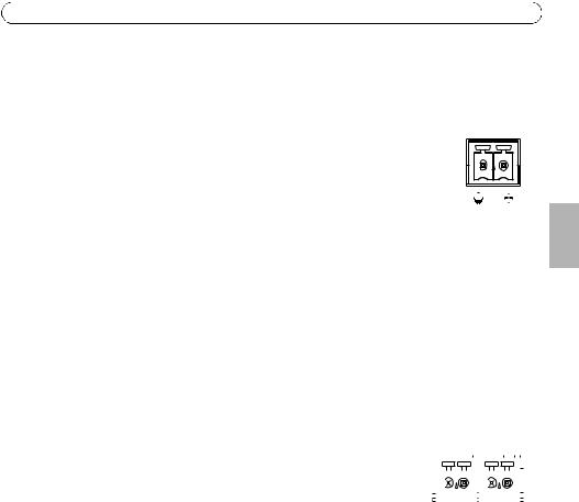
Power input connector - 2-pin terminal block used for power input from the supplied power adapter or an external power supply.
The external power supply alternatives are:
1. |
The Axis delivered PS-K P/N 34987 (AXIS M7014). |
|
|
|
|
|||
1 |
2 |
|||||||
2. |
The Axis delivered PS-P P/N 42118 (AXIS M7010). |
|||||||
|
|
|
|
|||||
3. |
An external 8-20 V DC limited power source with a maximum output current of 5A. |
|
|
|
|
|||
|
|
|
|
|
|
|
||
Function |
Pin number |
Description |
|
|
|
|
||
|
|
|
|
|
|
|
||
GND |
1 |
Ground |
|
|
|
|
||
|
|
|
|
|
|
|
||
DC Power |
2 |
Power input 8-20V DC |
|
|
|
|
||
|
|
|
max 7W (AXIS M7014) |
|
|
|
|
|
|
|
|
max 28W (AXIS M7010) |
|
|
|
|
|
|
|
|
|
|
|
|
|
|
RS-485/RS-422 connector - Two 2-pin terminal blocks for RS-485/RS-422 serial interface used to control auxiliary equipment, e.g. PTZ devices.
The RS-485/RS-422 serial port can be configured to support: |
|
RS-485/422 |
|
|
|
|
||||||||||||||||||||
|
|
|
|
|
|
|
|
|
||||||||||||||||||
• Two-wire RS-485 half duplex |
|
|
|
|
|
|
|
|
|
|
|
|
|
|
|
|
|
|
|
|
|
|
|
|||
• Four-wire RS-485 full duplex |
|
|
|
|
|
|
|
|
|
|
|
|
|
|
|
|
|
|
|
|
|
|
|
|||
|
|
|
|
|
|
|
|
|
|
|
|
|
|
|
|
|
|
|
|
|
|
|
||||
|
|
|
|
|
|
|
|
|
|
|
|
|
|
|
|
|
|
|
|
|
|
|
||||
• Two-wire RS-422 simplex |
|
|
|
|
|
|
|
|
|
|
|
|
|
|
|
|
|
|
|
|
|
|
|
|
||
|
|
|
|
|
|
|
|
|
|
|
|
|
|
|
|
|
|
|
|
|
|
|
|
|||
• Four-wire RS-422 full duplex point to point communication |
RX/TX |
|
|
TX |
|
|
|
|
||||||||||||||||||
1 |
|
|
2 |
|
|
3 |
|
|
|
4 |
|
|||||||||||||||
|
|
|
|
|
|
|
|
|
|
|
|
|||||||||||||||
|
|
|
|
|
|
|
|
|
|
|
|
|
|
|
|
|
|
|
|
|
|
|
|
|
|
|
Function |
|
Pin |
Notes |
|
|
|
|
|
|
|
|
|
|
|
|
|
|
|
|
|
|
|
|
|
|
|
|
|
|
|
|
|
|
|
|
|
|
|
|
|
|
|
|
|
|
|
|
|
|
|
|
|
|
RS-485/RS-422 RX/TX A |
1 |
(RX) For full duplex RS-485/RS-422 |
|
|
|
|
|
|
|
|
|
|
|
|
|
|
|
|
|
|
|
|
|
|
|
|
|
|
|
(RX/TX) For half duplex RS-485 |
|
|
|
|
|
|
|
|
|
|
|
|
|
|
|
|
|
|
|
|
|
|
|
RS-485/RS-422 |
RX/TX B |
2 |
|
|
|
|
|
|
|
|
|
|
|
|
|
|
|
|
|
|
|
|
|
|
|
|
|
|
|
|
|
|
|
|
|
|
|
|
|
|
|
|
|
|
|
|
|
|
|
|
|||
|
|
|
|
|
|
|
|
|
|
|
|
|
|
|
|
|
|
|
|
|
|
|
|
|
|
|
RS-485/RS-422 |
TX A |
3 |
(TX) For full duplex RS-485/RS-422 |
|
|
|
|
|
|
|
|
|
|
|
|
|
|
|
|
|
|
|
|
|
|
|
|
|
|
|
|
|
|
|
|
|
|
|
|
|
|
|
|
|
|
|
|
|
|
|
|
|
|
RS-485/RS-422 |
TX B |
4 |
|
|
|
|
|
|
|
|
|
|
|
|
|
|
|
|
|
|
|
|
|
|
|
|
|
|
|
|
|
|
|
|
|
|
|
|
|
|
|
|
|
|
|
|
|
|
|
|
|
|
|
microSD memory card slot - The microSD memory card can be used for local recording with removable storage.
BNC connector - Connect a 75 ohm coaxial video cable (max. length 800 feet (250 meters)).
Note: For each video input 75 Ohm video termination can be enabled/disabled via the product's web page at Video > Video Input > Video termination. These terminations are enabled on factory default. In cases
ENGLISH

Page 16 |
AXIS M7014/M7010 Installation Guide |
where the product is to be connected in parallel with other equipment, for optimum video quality, it is recommended that termination be enabled for only the last device in the video signal chain.
LED indicators
LED |
Color |
Indication |
|
|
|
Network |
Green |
Steady for connection to a 100 Mbit/s network. Flashes for network activity. |
|
|
|
|
Amber |
Steady for connection to 10 Mbit/s network. Flashes for network activity. |
|
|
|
|
Unlit |
No network connection. |
|
|
|
Status |
Green |
Steady green for normal operation. |
|
|
|
|
Amber |
Steady during startup, during reset to factory default or when restoring settings. |
|
|
|
|
Red |
Slow flash for failed upgrade. |
|
|
|
Power |
Green |
Normal operation. |
|
|
|
|
Amber |
Flashes green/amber during firmware upgrade. |
|
|
|

AXIS M7014/M7010 Installation Guide |
Page 17 |
Resetting to the factory default settings
This will reset all parameters, including the IP address, to the Factory Default settings:
1.Disconnect the power from the AXIS M7014/M7010, or if PoE is used disconnect the network cable.
2.Press and hold the Control button and reconnect power or the network cable if PoE is used.
3.Keep the Control button pressed until the Status indicator displays amber (this may take up to 15 seconds).
4.Release the Control button. When the Status indicator displays green (which can take up to 1 minute) the process is complete and the video encoder has been reset.
5.Re-assign the IP address, using one of the methods described in this document.
It is also possible to reset parameters to the original factory default settings via the web interface. For more information, please see the online help or the user’s manual.
Accessing the AXIS M7014/M7010 from the Internet
Once installed, your AXIS M7014/M7010 is accessible on your local network (LAN). To access the video encoder from the Internet, network routers must be configured to allow incoming traffic, which is usually done on a specific port.
•HTTP port (default port 80) for viewing and configuration
•RTSP port (default port 554) for viewing H.264 video streams
Please refer to the documentation for your router for further instructions. For more information on this and other topics, visit the Axis Support Web at www.axis.com/techsup
Further information
The user’s manual is available from the Axis Web site at www.axis.com or from the Axis Network Video Product CD supplied with this product.
Tip!
Visit www.axis.com/techsup to check if there is updated firmware available for your AXIS M7014/M7010. To see the currently installed firmware version, see the About web page.
ENGLISH
Mesures de sécurité
Lisez attentivement ce guide d’installation avant d’installer le produit. Conservez le guide d’installation pour une utilisation ultérieure.
 ATTENTION!
•Pour éviter d’endommager le produit Axis, utilisez l’emballage d’origine ou un emballage équivalent pour le transporter.
•Conservez le produit Axis dans un environnement sec et aéré.
•Évitez d’exposer le produit Axis à des vibrations, des chocs ou une trop forte pression et ne l’installez pas sur des supports instables, ou encore sur des surfaces ou des murs instables ou vibrants; cela risquerait de l’endommager.
•Utilisez uniquement des outils à main pour l’installation du produit Axis: l’utilisation d’outils électriques ou l’usage excessif de la force risquent de l’endommager.
•N’utilisez ni produits chimiques, ni substances caustiques, ni nettoyeurs aérosol. Utilisez un chiffon humide pour le nettoyage.
•N’utilisez que des accessoires conformes aux caractéristiques techniques du produit. Ceux-ci peuvent être fournis par Axis ou un fournisseur tiers.
•Utilisez uniquement des pièces de rechange fournies ou recommandées par Axis.
•Ne tentez pas de réparer le produit vous-même, contactez Axis ou votre revendeur Axis pour tout problème de maintenance.
 IMPORTANT!
•Ce produit Axis doit être utilisé conformément aux lois et réglementations locales en vigueur.
Remplacement des piles
Ce produit Axis nécessite une pile au lithium CR2032 de 3V pour l’alimentation de son horloge en temps réel interne. Dans des conditions normales d’utilisation, cette pile est censée durer au moins 5ans. Si la pile est faible, le fonctionnement de l’horloge en temps réel peut être affecté et entraîner sa réinitialisation à chaque mise sous tension. Un message enregistré apparaît lorsque la pile doit être remplacée. Ne remplacez la pile que lorsque cela est nécessaire.
Si la pile doit être remplacée, veuillez contacter www.axis.com/techsup pour obtenir de l’aide.
•Le remplacement incorrect de la pile peut entraîner un risque d’explosion.
•Remplacez la pile par une pile identique ou équivalente uniquement, en respectant les recommandations du fabricant.
•Jetez les piles usagées conformément aux consignes du fabricant.

AXIS M7014/M7010 Guide d’installation |
Page 19 |
Encodeur vidéo AXIS M7014/M7010 Guide d’installation
Ce guide d’installation vous explique comment installer l’encodeur vidéo AXIS M7014/M7010 sur votre réseau. Pour toute autre question concernant l’utilisation du produit, reportez-vous au manuel de l’utilisateur du produit, que vous trouverez sur le CD joint ou sur le site www.axis.com
Procédure d’installation
Procédez comme suit pour installer l’AXIS M7014/M7010 sur votre réseau local (LAN) : 1. Vérifiez le contenu de l’emballage par rapport à la liste ci-dessous.
2.Vue d’ensemble du matériel. Reportez-vous à la page 20.
3.Installation du matériel. Reportez-vous à la page 21.
4.Attribution d’une adresse IP. Reportez-vous à la page 23.
5.Configuration du mot de passe. Reportez-vous à la page 27.
Important !
Ce produit doit être utilisé conformément aux lois et réglementations locales en vigueur.
 Contenu de l’emballage
Élément |
Modèles/variantes/remarques |
|
|
Modèles d’encodeur vidéo |
AXIS M7014 |
Axis |
AXIS M7010 |
|
|
Modèles d’adaptateur |
AXIS M7014 : type PS-K |
secteur |
AXIS M7010 : type PS-P |
|
|
Kit de montage |
AXIS M7014 |
|
• 4 vis et 4 chevilles pour monter l’encodeur sur un mur en béton |
|
AXIS M7010 |
|
• 8 vis (pour montage avec supports) |
|
• 2 supports de fixation |
|
• 4 vis M6x20 pour montage dans le rack |
|
AXIS M7014/M7010 |
|
• 4 patins de protection de surface |
|
• Connecteurs pour terminaux (RS-485/RS-422 : Connecteur à |
|
2 x 2 broches pour AXIS M7014 ; connecteur à 8 x 2 broches |
|
pour AXIS M7010, Alimentation : connecteur à 2 broches) |
|
|
CD |
CD du produit de vidéo sur IP Axis, comprenant une documentation, des |
|
outils d’installation et des logiciels complémentaires |
|
|
Documentation imprimée |
Guide d’installation AXIS M7014/M7010 (le présent document) |
|
Document de garantie Axis |
|
|
AISÇFRAN
Page 20 |
AXIS M7014/M7010 Guide d’installation |
Présentation du matériel
|
|
AXIS M7014 |
|
Vue de face |
|
Vue arrière |
Bouton de commande |
|
|
|
|
Trous de fixation |
|
|
Connecteur réseau (PoE) |
|
|
Logement de carte |
|
|
|
micro SD |
|
Témoins DEL pour |
Connecteurs d’entrée vidéo |
Connecteur d’alimentation |
|
|
|||
|
|
|
|
l’alimentation, l’état et le réseau |
Connecteur RS-485/RS-422 |
||
|
|
||
|
|
|
|
AXIS M7010 - vue arrière |
|
Bouton de command |
||
|
|
|
PoE |
PoE |
|
PoE |
|
PoE |
PW R |
M EM O RY |
RS-485/422 |
M EM O RY |
RS-485/422 |
M EM O RY |
RS-485/422 |
M EM O RY |
RS-485/422 |
|
CARD |
|
CARD |
|
CARD |
|
CARD |
|
- + |
|
RX/TX TX |
|
RX/TX TX |
|
RX/TX TX |
|
RX/TX TX |
|
4 |
|
3 |
|
2 |
|
1 |
|
Connecteur Connecteur d’alimentation Logement de RS-485/RS-422
carte micro SD Connecteur réseau (PoE)
|
|
|
Connecteurs d’entrée vidéo |
AXIS M7010 - vue avant |
|
|
|
|
|
|
|
|||||||||
|
1 |
|
|
|
|
|
|
|
|
|
|
|
|
|
|
|
|
|
|
AXIS M7010 |
NE T |
|
2 |
3 |
4 |
NE T |
1 |
2 |
3 |
4 |
NE T |
1 |
2 |
3 |
4 |
NE T |
1 |
2 |
3 |
4 |
Video Encoder |
S TAT |
|
|
|
|
S TAT |
|
|
|
|
S TAT |
|
|
|
|
S TAT |
|
|
|
|
|
PWR |
PWR |
PWR |
PWR |
1 |
2 |
3 |
4 |
Groupe 1 |
Groupe 2 |
Groupe 3 |
Groupe 4 |
(4 connecteurs d’entrée vidéo) |
|
Voyants lumineux |
|
|
|
|
|
Dimensions
AXIS M7014 |
H x L x P = 37 x 109 x 172 |
|
Poids = 570 g |
|
|
AXIS M7010 |
H x L x P = 45 x 440 x 165 |
|
Poids = 2 540 g |
|
|
AXIS M7014/M7010 Guide d’installation |
Page 21 |
 Installation du matériel
Important !
Le boîtier du système AXIS M7014/M7010 n’est pas approuvé pour une utilisation à l’extérieur ; le produit doit être uniquement installé en intérieur.
Remarques :
•Le système AXIS M7014/M7010 peut être placé sur une surface plane ou il peut être monté. Reportez-vous aux instructions de montage ci-dessous.
•Sortez les patins de protection de leur emballage et collez-les sur le dessous de l’encodeur vidéo pour éviter de rayer la surface sur laquelle l’encodeur vidéo est placé.
Montage de l’encodeur vidéo (AXIS M7014)
L’encodeur vidéo est fourni avec un kit de montage contenant des vis et des chevilles pour la fixation de l’encodeur vidéo sur un mur en béton :
1.Placez l’encodeur vidéo contre le mur et marquez l’emplacement des quatre trous de fixation (voir l’image à la page 20).
2.Percez les quatre trous de fixation.
3.Insérez les chevilles fournies dans le mur et fixez l’encodeur vidéo au mur à l’aide des vis fournies.
Montage de l’encodeur vidéo (AXIS M7010)
L’encodeur vidéo est fourni avec un kit de montage contenant des supports et des vis. L’appareil peut être monté dans un rack ou sur un mur.
Après avoir retiré les 4 vis, fixez le support de fixation à l’encodeur vidéo à un angle adapté pour une installation dans un rack standard 1U 19 pouces (482,6 mm) ou sur un mur.
|
AXIS M7010 dans le rack |
AXIS M7010 sur un mur |
Groupe 1 |
Groupe 2 Groupe 3 Groupe 4 |
|
|
Support de fixation |
|
Position du support pour un montage sur rack |
Position du support pour un montage mural |
|
Dans ce sens (vers le haut) |
|
|
|
Dispositif |
Dans ce sens |
|
|
|
|
Dans ce sens |
(vers le haut) |
|
|
|
|
(vers le haut) |
|
AISÇFRAN

Page 22 |
AXIS M7014/M7010 Guide d’installation |
Remarque : Chaque support doit être fixé sur le côté approprié de l’encodeur vidéo et à un angle approprié selon le montage du dispositif : sur un mur ou dans un rack.
Montage mural
1.Placez l’encodeur vidéo contre le mur avec les supports et marquez l’emplacement des quatre trous de fixation pour chaque support (voir l’image ci-dessus).
2.Percez les quatre trous de fixation.
3.Fixez l’encodeur vidéo au mur à l’aide des vis appropriées.
Branchement des câbles
1.Branchez l’encodeur au réseau à l’aide des câbles réseau blindés. En cas d’utilisation du PoE, voir la remarque ci-dessous.
2.Connectez la caméra aux entrées vidéo.
3.Si l’appareil est alimenté avec une entrée en CC, branchez l’adaptateur secteur d’intérieur fourni ou une alimentation externe. Voir la remarque ci-dessous.
4.Vérifiez que les témoins DEL indiquent les bonnes conditions. Pour plus d’informations, consultez le tableau à la page 32.
Remarque : L’appareil peut être alimenté à l’aide d’une alimentation en courant continu ou d’un PoE.
Si l’appareil est alimenté par une alimentation en courant continu, branchez l’alimentation au connecteur d’alimentation situé à l’arrière de l’appareil.
Si l’appareil est alimenté en PoE, branchez un câble réseau PoE. Pour un encodeur vidéo AXIS M7010, branchez 4 câbles réseau PoE (un par groupe).
AXIS M7014/M7010 Guide d’installation |
Page 23 |
 Attribution d’une adresse IP
Aujourd’hui, la plupart des réseaux sont équipés d’un serveur DHCP qui attribue automatiquement des adresses IP aux périphériques connectés. Si ce n’est pas le cas de votre réseau, l’AXIS M7014 utilisera l’adresse IP par défaut 192.168.0.90.
L’encodeur vidéo AXIS M7010 utilise 4 adresses IP différentes pour chaque groupe de 4 connecteurs d’entrée vidéo. Les numéros situés sur l’encodeur vidéo indiquent chaque ensemble de 4 adresses IP. 192.168.0.90 est l’adresse IP par défaut pour le groupe 1, 192.168.0.91 est l’adresse IP par défaut pour le groupe 2, 192.168.0.92 est l’adresse IP par défaut pour le groupe 3 et 192.168.0.93 est l’adresse IP par défaut pour le groupe 4.
Il est conseillé d’utiliser AXIS IP Utility et AXIS Camera Management pour configurer une adresse IP sous Windows. Ces deux applications gratuites sont disponibles sur le CD joint à votre produit de vidéo sur IP Axis. Vous pouvez également les télécharger à partir du site www.axis.com/ techsup. Choisissez la méthode qui vous convient le mieux, selon le nombre de caméras à installer.
Méthode |
Recommandée pour |
Système |
|
AISÇFRAN |
|
|
|||
|
|
d’exploitation |
|
|
|
|
|
|
|
AXIS IP Utility |
Un seul encodeur vidéo |
Windows |
|
|
Voir page 24 |
Petites installations |
|
|
|
|
|
|
||
|
|
|
|
|
AXIS Camera Management |
Plusieurs encodeurs vidéo |
Windows 2000 |
|
|
Voir page 25 |
Grandes installations |
Windows XP Pro |
|
|
|
Installation sur un autre sous- |
Windows 2003 Server |
|
|
|
réseau |
Windows Vista |
|
|
|
|
|
|
|
Remarques :
•En cas d’échec de l’attribution de l’adresse IP, vérifiez qu’aucun pare-feu ne bloque l’opération.
•Pour connaître les autres méthodes d’attribution ou de détection de l’adresse IP de votre AXIS M7014/ M7010, par exemple sur d’autres systèmes d’exploitation, reportez-vous à la page 29.
Page 24 |
AXIS M7014/M7010 Guide d’installation |
AXIS IP Utility - Une seule caméra/Petite installation
AXIS IP Utility recherche et affiche automatiquement les périphériques Axis présents sur votre réseau. Cette application peut également être utilisée pour attribuer manuellement une adresse IP statique.
Notez que l’ordinateur exécutant l’application AXIS IP Utility doit se trouver sur le même segment de réseau (sous-réseau physique) que l’AXIS M7014/M7010.
Détection automatique
1.Vérifiez que l’AXIS M7014/M7010 est connecté au réseau et sous tension.
2.Lancez AXIS IP Utility.
3.Lorsque l’icône AXIS M7014/M7010 apparaît dans la fenêtre, double-cliquez dessus pour en ouvrir la page d’accueil. L’encodeur vidéo
AXIS M7010 propose, dans la fenêtre, une entrée pour chacun de ses 4 groupes d’entrées vidéo.
4.Reportez-vous à la page 27 pour la configuration du mot de passe.
Configuration manuelle de l’adresse IP (facultatif)
1.Trouvez une adresse IP non utilisée sur le même segment de réseau que celui de votre ordinateur.
2.Sélectionnez un encodeur vidéo AXIS M7014 ou un des encodeurs vidéo AXIS M7010 dans la liste.
3.Cliquez sur le bouton  Assign new IP address to selected device (Attribuer une nouvelle adresse IP au périphérique sélectionné) et saisissez l’adresse IP.
4.Cliquez sur le bouton Assign (Attribuer) et suivez les instructions.
5.Cliquez sur le bouton Home Page (Page d’accueil) pour accéder aux pages Web de l’encodeur vidéo.
6.Reportez-vous à la page 27 pour la configuration du mot de passe.
AXIS M7014/M7010 Guide d’installation |
Page 25 |
AXIS Camera Management - plusieurs caméras/grandes installations
AXIS Camera Management peut rechercher et configurer automatiquement les adresses IP, afficher l’état de connexion et gérer les mises à niveau du micrologiciel de plusieurs produits de vidéo sur IP Axis.
Détection automatique
1.Vérifiez que l’encodeur est connecté au réseau et est sous tension.
2.Lancez AXIS Camera Management. Double-cliquez sur l’icône de l’encodeur vidéo lorsqu’elle apparaît dans la fenêtre afin d’ouvrir la page d’accueil de l’encodeur. L’encodeur vidéo AXIS M7010 propose, dans la fenêtre, une entrée pour chacun de ses quatre groupes de connecteurs d’entrées vidéo.
3.Reportez-vous à la page 27 pour la configuration du mot de passe.
Attribution d’une adresse IP à un seul périphérique
1.Sélectionnez l’encodeur vidéo dans l’application
AXIS Camera Management, puis cliquez sur le bouton Assign IP (Attribuer une adresse IP). 
2.Sélectionnez Assign the following IP address (Attribuer l’adresse IP suivante) et saisissez l’adresse IP, le masque de sous-réseau et le routeur par défaut que le périphérique utilisera.
3.Cliquez sur le bouton OK.
AISÇFRAN

Page 26 |
AXIS M7014/M7010 Guide d’installation |
Attribution d’adresses IP à plusieurs périphériques
AXIS Camera Management accélère le processus d’attribution d’adresses IP à plusieurs périphériques en suggérant des adresses IP dans une plage précisée.
1.Sélectionnez les périphériques à configurer (il peut s’agir de plusieurs modèles), puis cliquez sur le bouton Assign IP (Attribuer une adresse IP). 
2.Sélectionnez Assign the following IP address range
(Attribuer la plage d’adresses IP suivante) et saisissez la plage d’adresses IP, le masque de sous-réseau et le routeur par défaut que les périphériques utiliseront.
3.Cliquez sur le bouton OK.
Loading...