


 Loading...
AXIS 210/210A/211/211A
Network Camera
Installation Guide
ESPAÑOL ITALIANO DEUTSCH FRANCAIS ENGLISH


AXIS 210/210A/211/211A Installation Guide |
Page 3 |
AXIS 210/210A/211/211A
Installation Guide
This installation guide provides instructions for installing the AXIS 210/210A/211/211A Network Camera on your network. For all other aspects of using the product, please see the User’s Manual, available on the CD included in this package, or from www.axis.com/techsup
Installation steps
1.Check the package contents against the list below.
2.Hardware overview. See page 4.
3.Install the hardware. See page 6.
4.Set an IP address. See page 7.
5.Set the password. See page 10.
6.Adjust the focus. See page 11.
7.Change the camera’s web interface language (optional). See page 12.
Important!
This product must be used in compliance with local laws and regulations.
 Package contents
Item |
Models/variants/notes |
|
|
Network camera |
• AXIS 210 |
|
• AXIS 210A: PoE, two-way audio and built-in microphone |
|
• AXIS 211: PoE, Varifocal DC-iris lens |
|
• AXIS 211A: PoE, two-way audio and built-in microphone, Varifocal DC-iris |
|
lens |
|
|
PS-K indoor power supply |
Europe, UK, Australia, USA/Japan, Argentina, Korea |
(country specific) |
|
|
|
Camera stand |
Supplied with mounting screws |
|
|
Terminal block connector |
4-pin connector block for connecting external devices to the I/O terminal con- |
|
nector |
|
|
CD |
Axis Network Video Product CD, including installation tools a nd other soft- |
|
ware, product documentation |
|
|
Printed Materials |
AXIS 210/210A/211/211A Installation Guide (this document) |
|
Axis Warranty Document |
|
|
ENGLISH

Page 4 |
AXIS 210/210A/211/211A Installation Guide |
 Hardware overview
AXIS 210/AXIS 210A |
|
AXIS 211/AXIS 211A |
Status |
Status |
Tele/wide puller |
indicator |
indicator |
|
DC-Iris control cable
Focus puller |
Focus puller |
Underside

 Internal microphone (AXIS 210A/AXIS 211A)
Serial number
Control button
 Power indicator
 Network indicator
AXIS 210/210A/211/211A Installation Guide |
Page 5 |
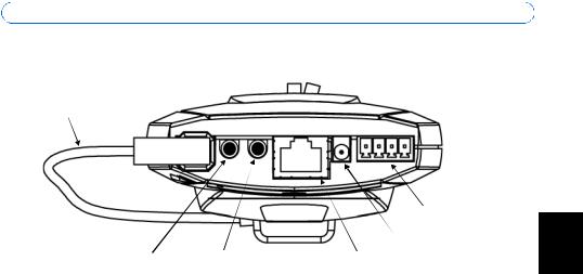
Rear panel
DC-Iris control cable (AXIS 211/211A)
4 3 2 1
|
|
I/O terminal |
|
|
connector |
|
|
Power connector |
External microphone/line input |
Audio output |
Network connector and PoE |
(AXIS 210A/211A) |
(AXIS 210A/211A) |
(AXIS 210A/211/211A) |
Note:
Depending on the product version of your AXIS 210/210A/211/211A, you will see one of two different types of I/O ternminal connectors. See I/O terminal connector, on page 15.
Dimensions
AXIS 210/210A:
HxWxD = 38 x 88 x 157mm (1.5” x 3.4” x 6.2”)
Weight (AXIS 210) = 305g (0.67lb) excl. power supply
Weight (AXIS 210A) = 325g (0.72lb) excl. power supply
AXIS 211/211A:
HxWxD = 38 x 95 x 178mm (1.5” x 3.7” x 7”)
Weight = 345g (0.76lb) excl. power supply
ENGLISH
Page 6 |
AXIS 210/210A/211/211A Installation Guide |
Install the hardware
!IMPORTANT! - The 210/210A is designed for indoor use only, and must always be positioned where it is not exposed to direct sunlight or strong halogen light, which can cause permanent damage to the camera’s image sensor. Damage as a result of exposure to strong light is not covered by the Axis warranty.
IMPORTANT! - The AXIS 211/211A is designed for indoor and outdoor use. To use the camera outdoors, it must be installed in an approved outdoor housing. Please see www.axis.com for more information on outdoor housings.
Connect the camera
1.Connect the Network Camera to your network using a standard network cable. Using Shielded Twisted Pair (STP) cables is recommended.
2.Optionally connect external input/output devices, e.g. alarm devices. See page 15 for information on the terminal connector pins.
3.Optionally connect an active speaker and/or external microphone.
4.Connect power, using one of the methods listed below:
•The supplied power connector.
•Power over Ethernet (PoE). If available, this is automatically detected when the network cable is connected (see above).
•The I/O terminal connector on the rear panel.
5.Check that the indicator LED:s indicate the correct conditions. See the table on page 16 for further details. Note that some LED:s can be disabled and may be unlit.

AXIS 210/210A/211/211A Installation Guide |
Page 7 |
 Assign an IP address
To make it accessible on the network, the AXIS 210/210A/211/211A must be assigned an IP address.
Depending on the number of cameras you wish to install, the recommended method for assigning IP addresses in Windows is either AXIS IP Utility or AXIS Camera Management. Use the method that best suits your purpose.
Both of these free applications are available on the Axis Network Video Product CD supplied with this product, or they can be downloaded from www.axis.com/techsup
|
|
|
|
ENGLISH |
Method |
Recommended for |
Operating system |
|
|
|
|
|||
|
|
|
|
|
AXIS IP Utility |
Single camera |
Windows |
|
|
See page 8 |
Small installations |
|
|
|
|
|
|
||
|
|
|
|
|
AXIS Camera Management |
Multiple cameras |
Windows 2000 |
|
|
See page 9 |
Large installations |
Windows XP Pro |
|
|
|
Installation on a different subnet |
Windows 2003 Server |
|
|
|
|
|
|
|
Notes:
•A network DHCP server is optional.
•The AXIS 210/210A/211/211A has the default IP address 192.168.0.90
•If assigning the IP address fails, check that there is no firewall blocking the operation.
•For other methods of assigning or discovering the IP address of the AXIS 210/210A/211/211A, e.g. in other operating systems, see page 10.

Page 8 |
AXIS 210/210A/211/211A Installation Guide |
AXIS IP Utility - single camera/small installation
AXIS IP Utility automatically discovers and displays Axis devices on your network. The application can also be used to manually assign a static IP address.
Note that the computer running AXIS IP Utility must be on the same network segment (physical subnet) as the AXIS 210/210A/211/211A.
Automatic discovery
1.Check that the AXIS 210/210A/211/211A is connected to the network and that power has been applied.
2.Start AXIS IP Utility.
3.When the camera appears in the window, double-click it to open its home page.
4.See page 10 for instructions on how to assign the password.
Assign the IP address manually
1.Acquire an unused IP address on the same network segment as your computer.
2.Click the button  Assign new IP address using serial number and enter the serial number and IP address for the AXIS 210/210A/211/211A. The serial number is located on the product label.
3.Click the Assign button and follow the instructions.
4.Click the Home Page button to access the camera’s web pages.
5.See page 10 for instructions on how to set the password.

AXIS 210/210A/211/211A Installation Guide |
Page 9 |
AXIS Camera Management - multiple cameras/large installations
AXIS Camera Management can automatically find and set IP addresses, show connection status, and manage firmware upgrades for multiple Axis video products.
ENGLISH
Automatic discovery
1.Check that the camera is connected to the network and that power has been applied.
2.Start AXIS Camera Management. When the AXIS 210/210A/211/211A appears in the window, double-click it to open the camera’s home page.
3.See page 10 for instructions on how to set the password.
Set the IP address in multiple devices
AXIS Camera Management speeds up the process of assigning IP addresses to multiple devices, by suggesting IP addresses from a specified range.
1.Select the devices you wish to configure (different models can be selected) and click the
Assign IP button.
2.Select Obtain IP addresses automatically (DHCP), click the Update button and the program will search in the specified range and suggest an IP address for each device. -or-
Enter the range of IP addresses, the subnet mask and default router that devices can use and click the Update button.

Page 10 |
AXIS 210/210A/211/211A Installation Guide |
 Set the password
When accessing the AXIS 210/210A/211/211A for the first time, the ‘Configure Root Password’ dialog will be displayed.
1.Enter a password and then re-enter it, to confirm the spelling. Click OK.
2.Enter the user name root in the dialog. Note: The default administrator user name root cannot be deleted.
3.Enter the password as set above, and click OK. If the password is lost, the AXIS 210/ 210A/211/211A must be reset to the factory default settings. See page 17.
4.If required, click Yes to install AMC (AXIS Media Control), which allows viewing of the video stream in Internet Explorer. You will need administrator rights on the computer to do this.The Live View page of the AXIS 210/210A/211/211A is displayed, with links to the Setup tools, which allow you to customize the camera.
Setup - Provides all the tools for configuring the camera to requirements.
 Help - Displays online help on all aspects of using the camera.
AXIS 210/210A/211/211A Installation Guide Page 11
 Adjust the image and focus
To focus the AXIS 210/210A, |
Focus puller |
|
unscrew the focus puller on |
||
|
||
the lens. Adjust the focus as |
|
|
required. Re-tighten the focus |
|
|
puller. |
|
To focus the AXIS 211/211A follow the instructions below.
1. From the Basic Configura- |
Zoom puller |
tion page in the setup |
(Tele/wide) |
tools, open the Focus |
|
adjustment page. |
Focus puller |
2.Set the DC-Iris to Disabled  and click Save.
3.Unscrew the zoom puller on the lens by turning it anti-clockwise. Adjust the zoom setting as required. Re-tighten the zoom puller.
4.Unscrew the focus puller on the lens. Adjust the focus as required. Re-tighten the focus puller.
5.From the Focus adjustment page, set the DC-Iris to Enabled and click Save.
Note: The DC-Iris should always be disabled while focusing the camera. This opens the iris to its maximum, which gives the smallest depth of field and thus the best conditions for correct focusing. When the focus is set with this method it will then be maintained in any light conditions.
Accessing the AXIS 210/210A/211/211A from the Internet
Once installed, your AXIS 210/210A/211/211A is accessible on your local network (LAN). To access the camera from the Internet, network routers must be configured to allow incoming traffic, which is usually done on a specific port. Please refer to the documentation for your router for further instructions. For more information on this and other topics, visit the Axis Support Web at www.axis.com/techsup
ENGLISH

Page 12 |
AXIS 210/210A/211/211A Installation Guide |
 Language interface
After you have installed the Network Camera, you can download and install a language module to change the camera’s web interface to a language other than English:
1.Go to Setup > Language.
2.Download the desired language from www.axis.com/techsup/ and save it temporarily to your computer.
3.Click the Browse button and locate the language file.
4.Click Upload Language. The language you uploaded will appear under Select Language.
5.Select the language you want to use with your Axis camera, and click Save.

AXIS 210/210A/211/211A Installation Guide |
Page 13 |
Other methods of assigning the IP address
The table below shows the other methods available for assigning or discovering the IP address. All methods are enabled by default, and all can be disabled.
|
Use in operating |
Notes |
|
|
|
system |
|
|
|
|
|
|
|
|
UPnP™ |
Windows |
When enabled on your computer, the camera is automatically |
|
|
|
|
detected and added to “My Network Places.” |
|
|
|
|
|
|
|
Bonjour |
MAC OSX |
Applicable to browsers with support for Bonjour. Navigate to the |
|
|
|
(10.4 or later) |
Bonjour bookmark in your browser (e.g. Safari) and click on the |
|
|
|
ENGLISH |
|||
|
|
link to access the camera’s web pages. |
|
|
|
|
|
|
|
AXIS Internet |
All |
A free service from Axis that allows you to quickly and simply |
|
|
Dynamic DNS |
|
install your camera. Requires an Internet connection with no |
|
|
Service |
|
HTTP proxy. See www.axiscam.net for more information. |
|
|
|
|
|
|
|
ARP/Ping |
All |
See below. The command must be issued within 2 minutes of |
|
|
|
|
connecting power to the camera. |
|
|
|
|
|
|
|
View DHCP server |
All |
To view the admin pages for the network DHCP server, please see |
|
|
admin pages |
|
the server’s own documentation. |
|
|
|
|
|
|
|
Set the IP address with ARP/Ping
1.Acquire an IP address on the same network segment your computer is connected to.
2.Locate the serial number (S/N) on the AXIS 210/210A/211/211A label.
3.Open a command prompt on your computer and enter the following commands:
Windows syntax |
Windows |
example |
|
|
|
arp -s <IP Address> <Serial Number> |
arp -s 192.168.0.125 00-40-8c-18-10-00 |
|
ping -l 408 -t <IP Address> |
ping -l |
408 -t 192.168.0.125 |
UNIX/Linux/Mac syntax |
UNIX/Linux/Mac example |
|
|
|
|
arp -s <IP Address> <Serial Number> temp |
arp -s 192.168.0.125 00:40:8c:18:10:00 |
|
ping -s 408 <IP Address> |
temp |
408 192.168.0.125 |
|
ping -s |
|
4.Check that the network cable is connected to the camera and then start/restart the camera, by disconnecting and reconnecting power.
5.Close the command prompt when you see ‘Reply from 192.168.0.125: ...’ or similar.
6.In your browser, type in http://<IP address> in the Location/Address field and press Enter on your keyboard.
Notes:
•To open a command prompt in Windows: from the Start menu, select Run... and type cmd. Click OK.
•To use the ARP command on a Mac OS X, use the Terminal utility in Application > Utilities.

Page 14 |
AXIS 210/210A/211/211A Installation Guide |
Unit connectors
Network connector - RJ-45 Ethernet connector. Supports Power over Ethernet. Using Shielded Twisted Pair (STP) cables is recommended.
Power connector - Mini DC connector. 7-20V DC, max 5W.
Audio in - 3.5mm input for a mono microphone, or a line-in mono signal (left channel is used from a stereo signal).
Audio out - Audio output (line level) that can be connected to a public address (PA) system or an active speaker with a built-in amplifier. A pair of headphones can also be attached. A stereo connector must be used for the audio out.

AXIS 210/210A/211/211A Installation Guide |
Page 15 |
I/O terminal connector - Used in applications for e.g. motion detection, event triggering, time lapse recording, alarm notifications, etc. It provides the interface to:
• 1 transistor output - For connecting external devices such as relays and LEDs. Connected devices can be activated by AXIS VAPIX API, output buttons on the Live View page or by an Event Type. The output will show as active (shown under Event Configuration > Port Status) if the alarm device is activated.
• 1 digital input - An alarm input for connecting devices that can toggle between an open and closed circuit, for example: PIRs, door/window contacts, glass break detectors, etc. When a signal is received the state changes and the input becomes active (shown under Event Configuration > Port Status).
• Auxiliary power and GND. |
ENGLISH |
|
|
|
|
|
|
|
|
|
|
|
|
|
|
|
|
|
|
|
|
|
|
|
|
|
|
|
|
|
|
|
|
|
|
|
|
|
|
|
|
|
|
|
|
|
|
|
|
|
|
|
|
|
|
|
|
|
|
|
|
|
|
|
|
|
|
|
|
|
|
|
|
|
|
|
|
|
|
|
|
|
|
|
|
|
|
|
|
|
|
|
|
|
|
|
|
|
|
|
|
|
|
|
|
|
|
|
|
|
|
|
|
|
|
|
|
|
|
|
|
|
|
|
|
|
|
|
|
|
|
|
|
|
|
|
|
|
|
|
|
|
||||||||||||||||||||||||
Pin 4 |
|
|
Pin 2 |
|
|
|
Pin 4 |
|
|
|
|
|
|
|||||||||||||||||||||||||||
|
|
|
|
|
Pin 2 |
|
||||||||||||||||||||||||||||||||||
|
|
|
|
|
|
|
|
Pin 3 |
|
|
|
|
|
|
|
|
|
Pin 1 |
|
|
|
|
|
|
||||||||||||||||
|
|
|
|
|
|
|
|
|
|
|
|
|
|
|
|
|
|
|
|
|
Pin 3 |
|
Pin 1 |
|||||||||||||||||
|
|
|
|
|
|
|
|
|
|
|
|
|
|
|
|
|
|
|
|
|
|
|
|
|
|
|
|
|
|
|
|
|
|
|
|
|||||
|
|
|
|
|
|
|
|
|
|
|
|
|
|
|
|
|
|
|
|
|
|
|
|
|
|
|
|
|
|
|
|
|
|
|
|
|
|
|
|
|
|
Function |
|
|
|
Pin number |
|
Notes |
|
Specifications |
|||||||||||||||||||||||||||||||
|
|
|
|
|
|
|
|
|
|
|
|
|
|
|
|
|
|
|
|
|
|
|
|
|
|
|
|
|
|
|
|
|
|
|
|
|
|
|
|
|
|
Transistor |
|
|
|
4 |
|
|
|
|
|
|
|
|
|
|
|
|
Uses an open-collector NPN transistor with |
|
Max load = 50mA |
||||||||||||||||||||
|
Output |
|
|
|
|
|
|
|
|
|
|
|
|
|
|
|
|
|
|
the emitter connected to the GND pin. If used |
|
Max voltage = 24V DC |
||||||||||||||||||
|
|
|
|
|
|
|
|
|
|
|
|
|
|
|
|
|
|
|
|
|
|
|
|
|
|
|
|
|
|
|
|
with an external relay, a diode must be con- |
|
(to the transistor) |
||||||
|
|
|
|
|
|
|
|
|
|
|
|
|
|
|
|
|
|
|
|
|
|
|
|
|
|
|
|
|
|
|
|
nected in parallel with the load, for protec- |
|
|
|
|
|
|
||
|
|
|
|
|
|
|
|
|
|
|
|
|
|
|
|
|
|
|
|
|
|
|
|
|
|
|
|
|
|
|
|
tion against voltage transients. |
|
|
|
|
|
|
||
|
|
|
|
|
|
|
|
|
|
|
|
|
|
|
|
|
|
|
|
|
|
|
|
|
|
|
|
|
|
|
|
|
|
|
|
|
|
|
|
|
|
Digital Input |
|
|
|
3 |
|
|
|
|
|
|
|
|
|
|
|
|
Connect to GND to activate, or leave floating |
|
Must not be exposed to |
||||||||||||||||||||
|
|
|
|
|
|
|
|
|
|
|
|
|
|
|
|
|
|
|
|
|
|
|
|
|
|
|
|
|
|
|
|
(or unconnected) to deactivate. |
|
voltages greater than |
||||||
|
|
|
|
|
|
|
|
|
|
|
|
|
|
|
|
|
|
|
|
|
|
|
|
|
|
|
|
|
|
|
|
|
|
|
|
10V DC |
||||
|
|
|
|
|
|
|
|
|
|
|
|
|
|
|
|
|
|
|
|
|
|
|
|
|
|
|
|
|
|
|
|
|
|
|
|
|
|
|
|
|
|
7 - 20 V DC |
|
|
|
2 |
|
|
|
|
|
|
|
|
|
|
|
|
Can be used to power auxiliary equipment. |
|
Max load = 50mA |
||||||||||||||||||||
|
Power |
|
|
|
|
|
|
|
|
|
|
|
|
|
|
|
|
|
|
|
|
|
|
|
|
|
|
|
||||||||||||
|
|
|
|
|
|
|
|
|
|
|
|
|
|
|
|
|
|
|
|
|
|
|
|
|
|
|
|
|
|
|
|
|
|
|
|
|
|
|
|
|
|
GND |
|
|
|
1 |
|
|
|
|
|
|
|
|
|
|
|
|
|
|
|
|
|
|
|
|
|
||||||||||||||
|
|
|
|
|
|
|
|
|
|
|
|
|
|
|
|
|
|
|
|
|
|
|
|
|
|
|
|
|
|
|
|
|
|
|
|
|
|
|
|
|

Page 16 |
AXIS 210/210A/211/211A Installation Guide |
Connection diagram
|
Switch |
|
|
|
3.3V |
Mode |
+ |
|
|
|
Power |
|
|
|
|
Supply |
PS-K 9W |
- |
+ |
|
|
2 |
|
|
|
|
e.g., doorbell |
|
Relay |
|
|
|
|
|
|
GND |
1 |
|
|
|
|
3 |
|
|
Device
4
LED indicators
LED |
Color |
Indication |
|
|
|
Network |
Green |
Steady for connection to a 100 Mbit/s network. Flashes for network activity. |
|
|
|
|
Amber |
Steady for connection to 10 Mbit/s network. Flashes for network activity. |
|
|
|
|
Unlit |
No network connection. |
|
|
|
Status |
Green |
Steady green for normal operation. |
|
|
Note: The Status LED can be configured to be unlit during normal operation, or to |
|
|
flash only when the camera is accessed. To configure, go to Setup > System Options |
|
|
> LED settings. See the online help files for more information. |
|
|
|
|
Amber |
Steady during startup, during reset to factory default or when restoring settings. |
|
|
|
|
Red |
Slow flash for failed upgrade. |
|
|
|
Power |
Green |
Normal operation. |
|
|
|
|
Amber |
Flashes green/amber during firmware upgrade. |
|
|
|

AXIS 210/210A/211/211A Installation Guide |
Page 17 |
Resetting to the Factory Default Settings
This will reset all parameters, including the IP address, to the factory default settings:
1.Disconnect power from the camera.
2.Press and hold the Control button and reconnect power.
3.Keep the Control button pressed until the Power indicator flashes amber (this may take up to 15 seconds).
4.Release the Control button. When the Power indicator displays green (which can take up to 1 minute) the process is complete and the camera has been reset.
5.Re-assign the IP address, using one of the methods described in this document.
It is also possible to reset parameters to the original factory default settings via the web interface. For more information, please see the online help or the user’s manual.
Further information
The user’s manual is available from the Axis Web site at www.axis.com or from the Axis Network Video Product CD supplied with this product.
Tip!
Visit www.axis.com/techsup to check if there is updated firmware available for your AXIS 210/210A/211/211A. To see the currently installed firmware version, see the Basic Configuration web page in the product’s Setup tools.
ENGLISH

AXIS 210/210A/211/211A Guide d’installation |
Page 19 |
AXIS 210/210A/211/211A
Guide d'installation
Ce guide d'installation vous explique comment installer la Caméra Réseau AXIS 210/210A/ 211/211A sur votre réseau. Pour d'autres informations sur l'utilisation de ce produit, consultez le Manuel de l'utilisateur, disponible sur le CD fourni ou sur www.axis.com/ techsup.
Étapes de l'installation
1. Vérifiez le contenu de la livraison à l'aide de la liste ci-dessous.
2.Présentation du matériel. Reportez-vous à la page 20.
3.Installation du matériel. Reportez-vous à la page 22.
4.Paramétrez une adresse IP. Reportez-vous à la page 23.
5.Définissez le mot de passe. Reportez-vous à la page 26.
6.Réglez la mise au point. Reportez-vous à la page 27.
7.Changez la langue de l'interface Web de la caméra (facultatif). Reportez-vous à la page 28.
 Contenu de l'emballage
Important !
Ce produit doit être utilisé conformément aux lois et dispositions locales en vigueur.
Article |
Modèles/variantes/remarques |
|
|
Caméra réseau |
• AXIS 210 |
|
• AXIS 210A : PoE, fonction audio bilatérale et microphone intégré |
|
• AXIS 211 : PoE, objectif à focale variable Iris DC |
|
• AXIS 211A : PoE, fonction audio bilatérale et microphone intégré, objectif à |
|
focale variable Iris DC |
|
|
Alimentation intérieure |
Europe |
secteur PS-K |
Royaume-Uni |
(dépend du pays) |
Australie |
|
États-Unis/Japon |
|
Argentine |
|
Corée |
|
|
Pied de la caméra |
Fourni avec des vis de montage |
|
|
Connecteur pour terminaux |
Connecteur 4 broches pour la connexion d'équipements externes au |
|
connecteur E/S |
|
|
CD |
CD du produit vidéo réseau Axis comprenant les outils d'installation, les autres |
|
logiciels et la documentation |
|
|
Documentation imprimée |
AXIS 210/210A/211/211A Guide d'installation (le présent document) |
|
Document de garantie d'Axis |
|
|
FRANCAIS

Page 20 |
AXIS 210/210A/211/211A Guide d’installation |
 Présentation du matériel
AXIS 210/AXIS 210A |
|
AXIS 211/AXIS 211A |
Voyant |
Voyant |
Zoom avant/arrière |
|
||
d'état |
d'état |
|
Câble de commande de l'iris DC
Mise au point |
Mise au point |
Vue de dessous

 Microphone interne (AXIS 210A/AXIS 211A)
Numéro de série
Bouton de commande
Voyant d'alimentation
 Voyant de réseau
AXIS 210/210A/211/211A Guide d’installation Page 21
Face arrière
Câble de commande de l’iris DC AXIS 211/211A)
4 3 2 1
|
|
Connecteur E/S |
|
|
Connecteur |
|
|
d’alimentation |
Microphone externe/entrée |
Sortie audio |
Connecteur de réseau et PoE |
de ligne (AXIS 210A/211A) |
(AXIS 210A/211A) |
(AXIS 210A/211/211A) |
Remarque: Suivant la version de votre AXIS 210/210A/211/211A, vous trouverez l'un des deux différents types de terminal de connexion d'E/S. Voir Connecteur pour terminaux E/S à la page 31.
Dimensions
AXIS 210/210A:
H x L x P =38 x 88 x 157mm (1,5 " x 3.4 " x 6.2 ")
Poids (AXIS 210) = 305 g (0,67 lb) alimentation exclue
Poids (AXIS 210A) = 325 g (0,72 lb) alimentation exclue
AXIS 211/211A:
H x L x P =38 x 95 x 178 mm (1,5 " x 3,7 " x 7 ")
Poids = 345 g (0,76 lb) alimentation exclue
FRANCAIS

Page 22 |
AXIS 210/210A/211/211A Guide d’installation |
 Installation du matériel
!IMPORTANT! - La caméra AXIS 210/210A est conçue pour une utilisation intérieure seulement. Elle ne doit jamais être exposée directement aux rayons du soleil ou à une forte lumière halogène pouvant endommager définitivement le capteur d'image de la caméra. La garantie d'Axis ne couvre pas les dommages suite à une exposition à une forte lumière.
IMPORTANT! - La caméra AXIS 211/211A est conçue pour une utilisation intérieure et extérieure. Pour pouvoir être utilisée à l'extérieur, la caméra doit être placée dans une housse homologuée. Visitez le site www.axis.com pour plus d'informations sur les housses.
Connectez la caméra
1.Connectez la caméra à votre réseau à l'aide d'un câble de réseau blindé. Il est recommandé d'utiliser des câbles à paires torsadées blindés (STP).
2.Si vous le souhaitez, connectez des dispositifs externes, par exemple des dispositifs d'alarme. Reportez-vous à la page 30 pour plus d'informations sur les broches du connecteur pour terminaux.
3.Si vous le souhaitez, connectez un haut-parleur actif pour la transmission audio bidirectionnelle.
4.Branchez l'alimentation à l'aide de l'une des méthodes reprises ci-dessous.
•PoE (Alimentation éléctrique par câble ethernet). Si disponible, ceci est automatiquement détecté quand le câble résau est connecté (Voir au -dessus).
•Branchez l'alimentation fournie au connecteur d'alimentation de la caméra.
•Branchez l'alimentation via le connecteur pour terminaux. Reportez-vous à la page 30 pour plus d'informations sur les broches du connecteur pour terminaux.
5.Vérifiez que les témoins DEL indiquent les conditions correctes. Pour plus d'informations, consultez le tableau à la page 32. Notez que certains témoins DEL peuvent être désactivés et éteints.

AXIS 210/210A/211/211A Guide d’installation |
Page 23 |
 Paramétrage d'une adresse IP
Pour que la caméra AXIS 210/210A/211/211A soit accessible sur le réseau, vous devez lui affecter une adresse IP.
Selon le nombre de caméras à installer, pour définir des adresses IP sous Windows, il est recommandé d'utiliser AXIS IP Utility ou AXIS Camera Management. Employez l'application qui vous convient le mieux.
Ces deux applications gratuites sont disponibles sur le CD de la caméra vidéo réseau Axis fourni avec ce produit. Vous pouvez également les télécharger à partir du site www.axis.com/techsup.
Méthode |
Recommandée pour |
Système |
|
|
|
|
d'exploitation |
|
|
|
|
|
|
|
AXIS IP Utility |
Une seule caméra |
Windows |
|
|
Reportez-vous à la page 24 |
Les petites installations |
|
|
|
|
|
|
|
FRANCAIS |
AXIS Camera Management |
Plusieurs caméras |
Windows 2000 |
|
|
|
|
|||
Reportez-vous à la page 25 |
Les grandes installations |
Windows XP Pro |
|
|
|
Le installation sur un sous- |
Windows 2003 Server |
|
|
|
réseaux différent |
|
|
|
|
|
|
|
|
|
|
|
|
|
Remarques
•Un serveur DHCP réseau est fourni en option.
•L'adresse IP par défaut de la AXIS 210/210A/211/211A est 192.168.0.90.
•En cas d'échec de la définition de l'adresse IP, vérifiez qu'aucun pare-feu ne bloque l'opération.
•Pour connaître les autres méthodes de paramétrage ou de repérage de l'adresse IP de la caméra AXIS 210/210A/211/211A, par exemple sur d'autres systèmes d'exploitation, reportez-vous à la page 33.

Page 24 |
AXIS 210/210A/211/211A Guide d’installation |
AXIS IP Utility - Une seule caméra/petite installation
L'utilitaire AXIS IP Utility détecte et affiche automatiquement les périphériques Axis de votre réseau. Cette application sert également à définir manuellement une adresse IP statique.
Notez que l'ordinateur exécutant l'application AXIS IP Utility doit se trouver sur le même segment de réseau (sous-réseau physique) que la caméra AXIS 210/210A/211/211A.
Détection automatique
1.Vérifiez que la caméra AXIS 210/210A/211/211A est connectée au réseau et que l'alimentation est activée.
2.Démarrez AXIS IP Utility.
3.Lorsque l'icône de la caméra apparaît dans la fenêtre, double-cliquez dessus pour ouvrir la page d'accueil correspondante.
4.Consultez la page 26 pour savoir comment définir le mot de passe.
Définissez manuellement l'adresse IP.
1.Trouvez une adresse IP inutilisée sur le même segment de réseau que celui de votre ordinateur.
2.Cliquez sur le bouton  Paramétrer une nouvelle adresse IP en utilisant le numéro de série, puis saisissez le numéro de série et l'adresse IP de votre caméra AXIS 210/210A/ 211/211A. Le numéro de série se trouve sur l'étiquette du produit.
3.Cliquez sur le bouton Paramétrer et suivez les instructions.
4.Cliquez sur le bouton Page d'accueil pour accéder aux pages Web de la caméra.
5.Consultez la page 26 pour savoir comment définir le mot de passe.

AXIS 210/210A/211/211A Guide d’installation |
Page 25 |
AXIS Camera Management - Plusieurs caméras/grandes installations
AXIS Camera Management détecte et définit automatiquement les adresses IP, affiche les états de connexion et gère les mises à niveau de microcode de nombreux produits vidéo Axis.
FRANCAIS
Détection automatique
1.Vérifiez que la caméra est connectée au réseau et que l'alimentation est activée.
2.Démarrez AXIS Camera Management. Double-cliquez sur l'icône AXIS 210/210A/211/ 211A lorsqu'elle apparaît dans la fenêtre de façon à ouvrir la page d'accueil.
3.Consultez la page 26 pour savoir comment définir le mot de passe.
Paramétrer l'adresse IP sur plusieurs appareils
AXIS Camera Management accélère le processus d'affectation d'adresses IP sur plusieurs appareils en suggérant les adresses IP parmi une plage spécifiée.
1.Sélectionnez les appareils à configurer (il peut s'agir de plusieurs modèles), puis cliquez sur le bouton Assign IP (Affecter une adresse IP).
2.Sélectionnez Obtain IP addresses automatically (DHCP) (Obtenir les adresses IP automatiquement (DHCP)), puis cliquez sur le bouton Update (Mettre à jour). L'application effectue une recherche dans la plage indiquée et suggère une adresse IP pour chaque appareil.
-ou-
Saisissez la plage d'adresses IP, le masque de sous-réseau et le routeur par défaut que les appareils peuvent utiliser, puis cliquez sur le bouton Update (Mettre à jour).
Loading...