


 Loading...
INSTALLATION GUIDE
AXIS Q7406 Video Encoder Blade
ESPAÑOL ITALIANO DEUTSCH AISÇFRAN ENGLISH

About this Document
This document includes instructions for installing the AXIS Q7406 on your network. Previous experience of networking will be beneficial when installing the product.
Legal Considerations
Video and audio surveillance can be prohibited by laws that vary from country to country. Check the laws in your local region before using this product for surveillance purposes.
This product includes six (6) H.264 decoder licenses. To purchase further licenses, contact your reseller.
Electromagnetic Compatibility (EMC)
This equipment generates, uses and can radiate radio frequency energy and, if not installed and used in accordance with the instructions, may cause harmful interference to radio communications. However, there is no guarantee that interference will not occur in a particular installation.
If this equipment does cause harmful interference to radio or television reception, which can be determined by turning the equipment off and on, the user is encouraged to try to correct the interference by one or more of the following measures: Re-orient or relocate the receiving antenna. Increase the separation between the equipment and receiver. Connect the equipment to an outlet on a different circuit to the receiver. Consult your dealer or an experienced radio/TV technician for help. Shielded (STP) network cables must be used with this unit to ensure compliance with EMC standards.
USA - This equipment has been tested and found to comply with the limits for a Class B computing device pursuant to Subpart B of Part 15 of FCC rules, which are designed to provide reasonable protection against such interference when operated in a commercial environment. Operation of this equipment in a residential area is likely to cause interference, in which case the user at his/her own expense will be required to take whatever measures may be required to correct the interference.
Canada - This Class B digital apparatus complies with Canadian ICES-003.
Europe - This digital equipment fulfills the requirements for radiated emission according to limit B of EN55022, and the requirements for immunity according to EN55024 residential and commercial industry.
Japan - This is a class B product based on the standard of the Voluntary Control Council for Interference from Information Technology Equipment (VCCI). If this is used near a radio or television receiver in a domestic environment, it may cause radio interference. Install and use the equipment according to the instruction manual.
Australia - This electronic device meets the requirements of the Radio communications (Electromagnetic Compatibility) Standard AS/NZS CISPR22.
Equipment Modifications
This equipment must be installed and used in strict accordance with the instructions given in the user documentation. This equipment contains no user-serviceable components. Unauthorized equipment changes or modifications will invalidate all applicable regulatory certifications and approvals.
Liability
Every care has been taken in the preparation of this document. Please inform your local Axis office of any inaccuracies or omissions. Axis Communications AB cannot be held responsible for any technical or typographical errors and reserves the right to make changes to the product and documentation without prior notice. Axis Communications AB makes no warranty of any kind with regard to the material contained within this document, including, but not limited to, the implied warranties of merchantability and fitness for a particular purpose. Axis Communications AB shall not be liable nor responsible for incidental or consequential damages in connection with the furnishing, performance or use of this material.
RoHS
This product complies with both the European RoHS directive, 2002/95/EC, and the Chinese RoHS regulations, ACPEIP.
WEEE Directive
The European Union has enacted a Directive 2002/96/EC on Waste Electrical and Electronic Equipment (WEEE Directive). This directive is applicable in the European Union member states.
The WEEE marking on this product (see right) or its documentation indicates that the product must not be disposed of together with household waste. To prevent possible harm to human health and/or the environment, the product must be disposed of in an approved and environmentally safe recycling process. For further information on how to dispose of this product correctly, contact the product supplier, or the local authority responsible for waste disposal in your area.
Business users should contact the product supplier for information on how to dispose of this product correctly. This product should not be mixed with other commercial waste.
Support
Should you require any technical assistance, please contact your Axis reseller. If your questions cannot be answered immediately, your reseller will forward your queries through the appropriate channels to ensure a rapid response. If you are connected to the Internet, you can:
•download user documentation and firmware updates
•find answers to resolved problems in the FAQ database. Search by product, category, or phrases
•report problems to Axis support by logging in to your private support area.
The AXIS Q7406 uses a 3.0V CR2032 Lithium battery, for more information please see page 91.
AXIS Q7406 Installation Guide |
Page 3 |
AXIS Q7406 Video Encoder Blade
Installation Guide
This installation guide provides instructions for installing the AXIS Q7406 Video Encoder Blade on your network. For all other aspects of using the product, please see the User’s Manual, available on the CD included in this package, or from www.axis.com/techsup
Important!
•To mount the hardware in either the AXIS 291 1U Video Server Rack or the AXIS Q7900 Rack, please see the Installation Guide for the respective encoder rack
•This product must be used in compliance with local laws and regulations.
Installation steps
1.Check the package contents against the list below.
2.Hardware overview. See page 4.
3.Install the hardware. See page 5.
4.Assign an IP address. See page 7.
5.Set the password. See page 10.
 Package contents
Item |
Models/variants/notes |
|
|
Video encoder |
AXIS Q7406 |
|
|
CD |
AXIS Network Video Product CD, including product documentation, |
|
installation tools and other software |
|
|
Printed Materials |
AXIS Q7406 Installation Guide (this document) |
|
Axis Warranty Document |
|
Extra serial number label |
|
|
Please contact your dealer if anything is missing or damaged.
ENGLISH

Page 4 |
AXIS Q7406 Installation Guide |
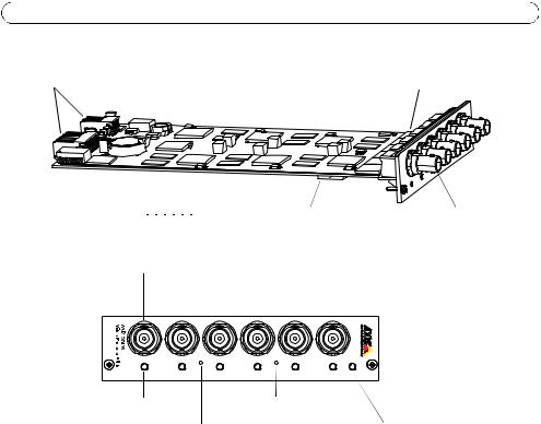
 Hardware overview
Bus connectors |
S/N & P/N label |
|
ON |
|
|
|
|
|
|
D I P |
|
DIP switches |
6 Video inputs |
|||||
|
|
|
|
|
|
|
|
|
|
|
|
|
|
|
||
|
|
|
|
|
|
|
|
|
|
|
|
|
|
|
||
|
1 |
|
2 |
|
3 |
|
4 |
|
|
5 |
|
6 |
|
|
|
|
Video inputs 1-6
1 |
2 |
3 |
4 |
5 |
POWER |
6 |
Status LEDs 1-6 |
Reset button |
Control button |
Power LED |
Dimensions
30 x 130 x 255 mm (1.2” x 5.1” x 10.0”) excluding connectors.
AXIS Q7406 Installation Guide |
Page 5 |
 Install the Hardware
The AXIS Q7406 is designed to be installed into the following video encoder racks.
•AXIS 291 1U Video Server Rack
•AXIS Q7900 Rack
Mounting the AXIS Q7406 into the AXIS 291 1U Video Server Rack
The AXIS 291 1U can accommodate 3 Axis blade video encoders. The slots for these are numbered 1-3 from left to right, as seen from the front. The I/O connectors for each slot on the rear panel are also numbered.
1.Remove a front panel cover from the slot in which the video encoder will be mounted. This is done by unfastening the screw on each side of the cover.
2.Slide the video encoder into place, using the guides as an aid. The dip switch for setting the line termination is visible on the bottom edge.
3.Fix the video encoder in place, using the screws from the front panel cover.
ENGLISH
Power LED
Notes:
• Do not leave empty slots on the AXIS 291 1U open, front panel covers must be used on all empty slots.
See the table Pin assignments for the I/O Connector of the AXIS 291 1U Video Server Rack, on page 14. For more information about the AXIS 291 1U see the installation guide for the AXIS 291 1U Video Server Rack.

Page 6 |
AXIS Q7406 Installation Guide |
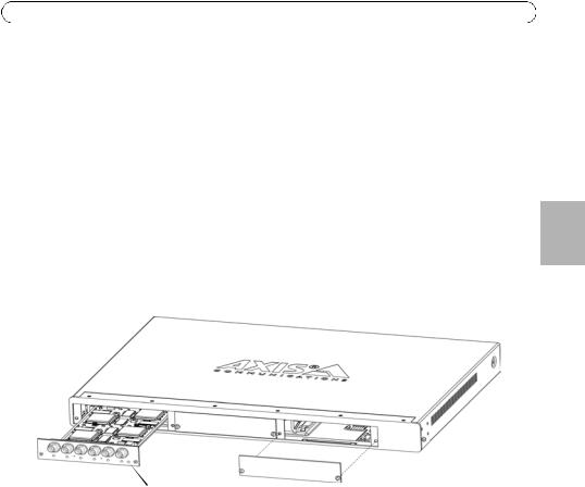
Mounting the AXIS Q7406 into the AXIS Q7900 Rack
The AXIS Q7900 can accommodate 14 Axis blade video encoders. The slots for these are numbered 1-14 from left to right, as seen from the front. The I/O connectors for each slot on the rear panel are also numbered.
1.Remove a front panel cover from the slot in which the video encoder will be mounted. This is done by unfastening the screw on each side of the cover.
2.Slide the video encoder into place, using the guides as an aid. The dip switch for setting the line termination should be visible on the bottom edge.
3.Fix the video encoder in place, using the screws from the front panel cover.

 Screws
Note: Front panel covers should be used on all empty slots.
See the tables Pin assignments for the I/O Connector of the AXIS Q7900 Rack, on page 15, and Pin assignments for the RS-485 Connector of the AXIS Q7900 Rack, on page 16 below for pin assignment information. For more information about the AXIS Q7900 see the installation guide for the AXIS Q7900 Rack.

AXIS Q7406 Installation Guide |
Page 7 |
 Assign an IP address
Most networks today have a DHCP server that automatically assigns IP addresses to connected devices. If your network does not have a DHCP server the AXIS Q7406 will use 192.168.0.90 as the default IP address for channel 1, 192.168.0.91 for channel 2, 192.168.0.92 for channel 3, 192.168.0.93 for channel 4, 192.168.0.94 for channel 5, and 192.168.0.95 as the default IP address for channel 6.
AXIS IP Utility and AXIS Camera Management are recommended methods for setting an IP address in Windows. These free applications are available on the Axis Network Video Product CD supplied with this product, or they can be downloaded from www.axis.com/techsup. Depending on the number of cameras you wish to install, use the method that suits you best.
Method |
Recommended for |
Operating system |
|
|
|
AXIS IP Utility |
Single video encoder |
Windows |
See page 8 |
Small installations |
|
|
|
|
AXIS Camera Management |
Multiple video encoder |
Windows 2000 |
See page 9 |
Large installations |
Windows XP Pro |
|
Installation on a different subnet |
Windows 2003 Server |
|
|
Windows Vista |
|
|
|
Notes:
•If assigning the IP address fails, check that there is no firewall blocking the operation.
•For other methods of assigning or discovering the IP address of the AXIS Q7406, e.g. in other operating systems, see page 12.
ENGLISH
Page 8 |
AXIS Q7406 Installation Guide |
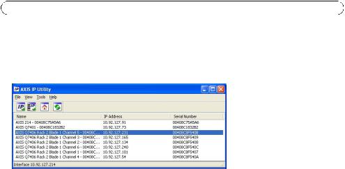
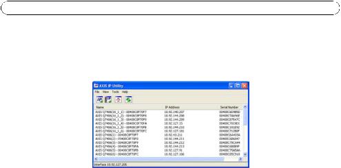
AXIS IP Utility
AXIS IP Utility automatically discovers and displays Axis devices on your network. The application can also be used to manually assign a static IP address.
Note that the computer running AXIS IP Utility must be on the same network segment (physical subnet) as the AXIS Q7406.
Automatic discovery
1.Check that the AXIS Q7406 is connected to the network and that power has been applied.
2.Start AXIS IP Utility.
3.When the AXIS Q7406 appears in the window, double-click an entry to open the home page for that video input.
•If the AXIS Q7406 is installed in an AXIS 291 1U, the AXIS Q7406 appears in the window with one entry for each of its six video inputs (e.g., AXIS Q7406(1)).
•If the AXIS Q7406 is installed in an AXIS Q7900, the AXIS Q7406 appears in the window with one entry for each of its six video inputs (e.g. AXIS Q7406 Rack 2 Blade 1 Channel 6).
4.See page 10 for instructions on how to assign the password.
Set the IP address manually (optional)
1.Acquire an unused IP address on the same network segment as your computer.
2.Select one of the AXIS Q7406s in the list.
3.Click the button  Assign new IP address to selected device and enter the IP address.
4.Click the Assign button and follow the instructions.
5.Click the Home Page button to access the video encoder’s web pages.
6.See page 10 for instructions on how to set the password.

AXIS Q7406 Installation Guide |
Page 9 |
AXIS Camera Management - multiple cameras/large installations
AXIS Camera Management can automatically find and set IP addresses, show connection status, and manage firmware upgrades for multiple Axis video products.
Automatic discovery
1.Check that the AXIS Q7406 is connected to the network and that power has been applied.
2.Start AXIS Camera Management.
3.When the AXIS Q7406 appears in the window, right-click the link and select Live View Home Page:
•If the AXIS Q7406 is installed in an AXIS 291 1U, the AXIS Q7406 appears in the window with one entry for each of its six video inputs (e.g., AXIS Q7406(1)).
•If the AXIS Q7406 is installed in an AXIS Q7900, the AXIS Q7406 appears in the window with one entry for each of its six video inputs (e.g. AXIS Q7406 Rack 2 Blade 1 Channel 6)
4.See page 10 for instructions on how to assign the password.
Assign an IP address in a single device
1.Select one of the AXIS Q7406s in AXIS Camera Management and click the Assign IP button. 
2.Select Assign the following IP address and enter the IP address, the subnet mask and default router the device will use.
3.Click the OK button.
Assign IP addresses in multiple devices
AXIS Camera Management speeds up the process of assigning IP addresses to multiple devices, by suggesting IP addresses from a specified range.
1.Select the devices you wish to configure (different models can be selected) and click the Assign IP button. 
2.Select Assign the following IP address range and enter the range of IP addresses, the subnet mask and default router the devices will use.
3.Click the OK button.
ENGLISH
Page 10 |
AXIS Q7406 Installation Guide |
 Set the password
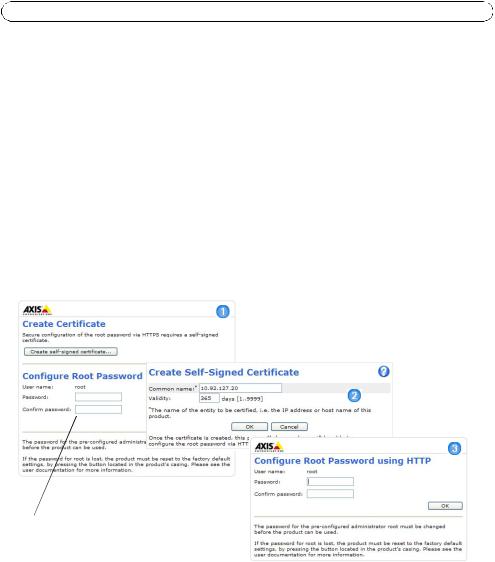
To gain access to the product, the password for the default administrator user root must be set. This is done in the ‘Configure Root Password’ dialog, which is displayed when the AXIS Q7406 is accessed for the first time.
To prevent network eavesdropping when setting the root password, this can be done via an encrypted HTTPS connection, which requires an HTTPS certificate (see note below).
To set the password via a standard HTTP connection, enter it directly in the first dialog shown below.
To set the password via an encrypted HTTPS connection, follow these steps:
1.Click the Create self-signed certificate button.
2.Provide the requested information and click OK. The certificate is created and the password can now be set securely. All traffic to and from the AXIS Q7406 is encrypted from this point on.
3.Enter a password and then re-enter it to confirm the spelling. Click OK. The password has now been configured.
To create an HTTPS connection,
 start by clicking this button.
To configure the password directly via an unencrypted connection, enter the password here.
4.To log in, enter the user name “root” in the dialog as requested. Note: The default administrator user name root cannot be deleted.
5.Enter the password as set above, and click OK. If the password is lost, the AXIS Q7406 must be reset to the factory default settings. See page 17.
6.If required, click Yes to install AMC (AXIS Media Control), which allows viewing of the video stream in Internet Explorer. You will need administrator rights on the computer to do this.
7.The Live View page of the AXIS Q7406 is displayed, with links to the Setup tools, which allow you to customize the video encoder.
AXIS Q7406 Installation Guide |
Page 11 |
Setup - Provides all the tools for configuring the video encoder to requirements.
Help - Displays online help on all aspects of using the video encoder.
ENGLISH
Notes:
•HTTPS (Hypertext Transfer Protocol over SSL) is a protocol used to encrypt the traffic between web browsers and servers. The HTTPS certificate controls the encrypted exchange of information.
•The default administrator user root cannot be deleted.
•If the password for root is lost or forgotten, the AXIS Q7406 must be reset to the factory default settings. See page 17.

Page 12 |
AXIS Q7406 Installation Guide |
Other methods of setting the IP address
The table below shows the other methods available for setting or discovering the IP address. All methods are enabled by default, and all can be disabled.
|
Use in operating |
Notes |
|
system |
|
|
|
|
UPnP™ |
Windows |
When enabled on your computer, the video encoder is |
|
|
automatically detected and added to “My Network Places.” |
|
|
|
Bonjour |
MAC OSX |
Applicable to browsers with support for Bonjour. Navigate to the |
|
(10.4 or later) |
Bonjour bookmark in your browser (e.g. Safari) and click on the |
|
|
link to access the video encoder’s web pages. |
|
|
|
AXIS Dynamic DNS |
All |
A free service from Axis that allows you to quickly and simply |
Service |
|
install your video encoder. Requires an Internet connection with |
|
|
no HTTP proxy. See www.axiscam.net for more information. |
ARP/Ping |
All |
See below. The command must be issued within 2 minutes of |
|
|
connecting power to the video encoder. |
View DHCP server |
All |
To view the admin pages for the network DHCP server, see the |
admin pages |
|
server’s own documentation. |
|
|
|
Set the IP address with ARP/Ping
1.Acquire 6 IP addresses on the same network segment your computer is connected to.
2.Locate the 6 serial numbers (S/N) on the AXIS Q7406 label.
3.Open a command prompt on your computer and enter the following commands:
Windows syntax |
|
Windows |
example |
|
|
||
arp -s <IP Address> <Serial Number> |
arp -s 192.168.0.125 00-40-8c-18-10-00 |
||
ping -l 408 -t |
<IP Address> |
ping -l |
408 -t 192.168.0.125 |
UNIX/Linux/Mac |
syntax |
UNIX/Linux/Mac example |
|
|
|
||
arp -s <IP Address> <Serial Number> temp |
arp -s 192.168.0.125 00:40:8c:18:10:00 temp |
||
ping -s 408 <IP Address> |
ping -s |
408 192.168.0.125 |
|
|
|
|
|
4.Check that the network cable is connected to the AXIS Q7406 and then start/restart the AXIS Q7406, by disconnecting and reconnecting power. If PoE is used, start/restart the AXIS Q7406 by disconnecting and then reconnecting the network cable.
5.Close the command prompt when you see ‘Reply from 192.168.0.125:...’ or similar.
6.Repeat steps 3, 4 and 5 for the remaining video inputs.
7.In your browser, type in http://<IP address> in the Location/Address field and press Enter on your keyboard.
Notes:
•To open a command prompt in Windows: from the Start menu, select Run... and type cmd. Click OK.
•To use the ARP command on a Mac OS X, use the Terminal utility in Application > Utilities.

AXIS Q7406 Installation Guide |
Page 13 |
Unit connectors
DIP Switches - Each video input has a corresponding line termination DIP switch. Axis blade video encoders are supplied with the line termination enabled for each input; that is, with the DIP switches set to ON (up position).
To connect the video input in parallel with other equipment, disable the input termination by setting the corresponding DIP switch to OFF (down position). Failure to do so may affect the image quality negatively.
Bus Connector - This is the physical interface to the video encoder rack, providing power, network and the I/O terminal connector.
Control Button - This button is used to reset the video encoder to the factory default settings. See page 17.
Reset Button - This button disconnects and reconnects power to the video encoder. See page 17.
Video Inputs - The AXIS Q7406 supports 6 video sources (VIDEO 1 - VIDEO 6). Each video input is terminated using a coax/BNC connector. Physical connections made using 75 Ohm coaxial video cable have a recommended maximum length of 800 feet (250 meters).
I/O Terminal Connector(s) (AXIS 291 1U) - Provides the physical interface to 2 configurable input/outputs on channels 1-2, and 1 configurable input/output for channels 3-6. Video input 1 on each blade also provides an RS-485 interface, usually used for connecting Pan Tilt Zoom devices. See Pin assignments for the I/O Connector of the AXIS 291 1U Video Server Rack, on page 14 for pin assignment information.
I/O Terminal Connector(s) (AXIS Q7900) - Provides the physical interface for up to 12 I/Os. See
Pin assignments for the I/O Connector of the AXIS Q7900 Rack, on page 15 for pin assignment information.
RS-485 Connector (AXIS Q7900) - Usually used for connecting Pan Tilt Zoom devices. See Pin assignments for the RS-485 Connector of the AXIS Q7900 Rack, on page 16 for pin assignment information.
ENGLISH

Page 14 |
AXIS Q7406 Installation Guide |
Pin assignments
Pin assignments for the I/O Connector of the AXIS 291 1U Video Server Rack
Pin |
Function |
Description |
|
|
|
|
|
|
|
1 |
+12V out, 100mA |
|
|
|
|
|
|
|
|
2 |
GND |
|
|
|
|
|
|
|
|
3 |
Channel 1, Configurable I/O 1 |
Digital input - Connect to GND to |
Min input = - 40V DC |
|
|
|
activate, or leave floating (or |
Max input = + 40V DC |
|
4 |
Channel 2, Configurable I/O 1 |
|||
unconnected) to deactivate. |
|
|||
|
|
|
||
5 |
Channel 3, Configurable I/O 1 |
|
||
|
|
|||
|
|
Digital output - Uses an open- |
Max load = 100mA |
|
6 |
Channel 4, Configurable I/O 1 |
|||
|
|
drain NFET transistor with the |
Max voltage = + 40V DC |
|
7 |
Channel 5, Configurable I/O 1 |
|||
source connected to GND. If used |
(to the transistor) |
|||
|
|
|||
8 |
Channel 6, Configurable I/O 1 |
with an external relay, a diode |
|
|
|
|
must be connected in parallel |
|
|
9 |
Channel 1, Configurable I/O 2 |
|
||
with the load, for protection |
|
|||
|
|
|
||
10 |
Channel 2, Configurable I/O 2 |
against voltage transients. |
|
|
|
|
|
|
|
11 |
Channel 1, RS485A |
A half-duplex RS-485 interface for controlling auxiliary equipment |
||
|
(non-inverting) (Video input 1) |
e.g. PTZ devices. |
|
|
|
|
|
|
|
12 |
Channel 1, RS485B |
|
|
|
|
(non-inverting) (Video input 1) |
|
|
|
|
|
|
|
|

AXIS Q7406 Installation Guide Page 15
Pin assignments for the I/O Connector of the AXIS Q7900 Rack
Pin |
Function |
Description |
|
|
|
|
|
|
|
|
|
1 |
Channel 1, Configurable I/O 1 |
Digital input - Connect to GND |
Min input = - 40V DC |
|
|
|
|
to activate, or leave floating (or |
Max input = + 40V DC |
|
|
2 |
Channel 2, Configurable I/O 1 |
|
|
||
unconnected) to deactivate. |
|
|
|
||
|
|
|
|
|
|
3 |
Channel 3, Configurable I/O 1 |
|
|
|
|
|
|
|
|
||
|
|
Digital output - Uses an open- |
Max load = 100mA |
|
|
4 |
Channel 4, Configurable I/O 1 |
|
|
||
|
|
drain NFET transistor with the |
Max voltage = + 40V DC |
|
|
5 |
Channel 5, Configurable I/O 1 |
|
|
||
source connected to GND. If |
(to the transistor) |
|
|
||
|
|
|
|||
6 |
Channel 6, Configurable I/O 1 |
used with an external relay, a |
|
|
|
|
|
ENGLISH |
|||
|
|
diode must be connected in |
|
|
|
7 |
Channel 1, Configurable I/O 2 |
|
|
|
|
parallel with the load, for |
|
|
|
||
|
|
|
|
|
|
8 |
Channel 2, Configurable I/O 2 |
|
|
|
|
protection against voltage |
|
|
|
||
|
|
transients. |
|
|
|
9 |
Channel 3, Configurable I/O 2 |
|
|
|
|
|
|
|
|||
|
|
|
|
|
|
10 |
Channel 4, Configurable I/O 2 |
|
|
|
|
|
|
|
|
|
|
11 |
Channel 5, Configurable I/O 2 |
|
|
|
|
|
|
|
|
|
|
12 |
Channel 6, Configurable I/O 2 |
|
|
|
|
|
|
|
|
|
|
The following connection diagram gives an example of how to connect an auxiliary device to the AXIS Q7406.
AXIS Q7406
E.g. push button
*12V max 100mA
3.3V
I/O configured as input
D |
I/O configured as output |
|
G
S

Page 16 |
AXIS Q7406 Installation Guide |
Pin assignments for the RS-485 Connector of the AXIS Q7900 Rack
Pin |
AXIS Q7406 |
|
|
1 |
Channel 1, RS485A |
|
|
2 |
Channel 1, RS485B |
|
|
3 |
Channel 2, RS485A |
|
|
4 |
Channel 2, RS485B |
|
|
5 |
Channel 3, RS485A |
|
|
6 |
Channel 3, RS485B |
|
|
7 |
Channel 4, RS485A |
|
|
8 |
Channel 4, RS485B |
|
|
9 |
Channel 5, RS485A |
|
|
10 |
Channel 5, RS485B |
|
|
11 |
Channel 6, RS485A |
|
|
12 |
Channel 6, RS485B |
|
|
Note: For RS-485 unit connector information for the AXIS Q7406 see Unit connectors, on page 13. For other video encoders, refer to their respective Installation Guide for I/O connector information.
LED Indicators
Status |
Green |
Steady green - normal operation |
|
Red |
One flash - the corresponding channel is starting up |
|
|
|
|
|
Two flashes - the corresponding channel is resetting to factory default settings |
|
|
|
|
|
Steady red - hardware error on the corresponding channel |
|
|
|
|
Green/red |
Flashes for no connection to AXIS Internet Dynamic DNS Service |
|
|
|
Power |
Green |
Normal operation |
|
Green/Amber |
Flashes for one or more channel upgrade |
|
|
|

AXIS Q7406 Installation Guide
Resetting to the Factory Default Settings
This will reset all the parameters in all 6 units (including all six IP addresses) to the factory default settings.
1. Press both the Reset button and Control button.
2. Release the Reset button and hold the Control button.
3. Keep the Control button pressed until the Power indicator turns green and the six Status indicators turn amber (this may take up to 15 seconds).
4. Release the Control button. When the Status indicators display green (which can take up to 1 minute) the process is complete and the video encoder has been reset.
5. Re-assign the IP addresses, using one of the methods described in this document.
To reset an individual unit to the original factory default settings, use the button provided in that unit’s web interface. For more information, please see the online help.
POWER
6 
5 
4 
3 
2 
1 
Page 17
Power Indicator
Status Indicator
Reset button
Control button
Accessing the AXIS Q7406 from the Internet
Once installed, your AXIS Q7406 is accessible on your local network (LAN). To access the video encoder from the Internet, network routers must be configured to allow incoming traffic, which is usually done on a specific port.
•HTTP port (default port 80) for viewing and configuration
•RTSP port (default port 554) for viewing H.264 video streams
Please refer to the documentation for your router for further instructions. For more information on this and other topics, visit the Axis Support Web at www.axis.com/techsup
Further information
The user’s manual is available from the Axis Web site at www.axis.com or from the Axis Network Video Product CD supplied with this product.
Tip!
Visit www.axis.com/techsup to check if there is updated firmware available for your AXIS Q7406. To see the currently installed firmware version, see the Basic Configuration web page in the product’s Setup tools.
ENGLISH
AXIS Q7406 Guide d'installation |
Page 19 |
Encodeur vidéo lame AXIS Q7406 Guide d'installation
Ce guide d'installation vous explique comment installer votre Encodeur vidéo lame AXIS Q7406 sur votre réseau. Pour toute autre information sur l'utilisation de ce produit, consultez le Manuel de l'utilisateur, que vous trouverez sur le CD fourni ou sur le site www.axis.com/techsup.
Important !
•Pour monter le matériel sur le Rack de serveur vidéo AXIS 291 1U ou sur le Rack AXIS Q7900, reportez-vous au Guide d’installation du rack concerné.
•Ce produit doit être utilisé conformément aux lois et dispositions locales en vigueur.
Étapes de l'installation
1.Vérifiez le contenu de la livraison à l'aide de la liste ci-dessous.
2.Présentation du matériel. Reportez-vous à la page 20.
3.Installation du matériel. Reportez-vous à la page 21.
4.Attribution d’une adresse IP. Reportez-vous à la page 23.
5.Configuration du mot de passe. Reportez-vous à la page 27.
 Contenu de l'emballage
Article |
Modèles/variantes/remarques |
|
|
Encodeur vidéo |
AXIS Q7406 |
|
|
CD |
CD du produit de vidéo sur IP AXIS comprenant les outils d'installation, |
|
les autres logiciels et la documentation |
|
|
Documentation |
Guide d'installation de l’AXIS Q7406 (le présent document) |
|
Document de garantie d'Axis |
|
Étiquette de numéro de série supplémentaire |
|
|
Veuillez contacter votre revendeur s’il manque des articles ou si certains sont endommagés.
AISÇFRAN
Page 20 |
AXIS Q7406 Guide d’installation |
 Présentation du matériel
Connecteurs de bus |
Étiquette de n° de série et de n° de pièce |
|
ON |
|
|
|
|
|
D I P |
|
Commutateurs DIP |
6 entrées vidéo |
|||||
|
|
|
|
|
|
|
|
|
|
|
|
|
|
||
|
|
|
|
|
|
|
|
|
|
|
|
|
|
||
|
1 |
|
2 |
|
3 |
|
4 |
|
5 |
|
6 |
|
|
|
|
Entrées vidéo 1 à 6
1 |
2 |
3 |
4 |
5 |
POWER |
6 |
DEL d’état 1 à 6 |
Bouton de réinitialisation |
|
Bouton de commande |
DEL d’alimentation |
|
Dimensions
30 x 130 x 255 mm, connecteurs exclus.
AXIS Q7406 Guide d'installation |
Page 21 |
 Installation du matériel
L’AXIS Q7406 est destiné à être installé sur les racks d’encodeur vidéo suivants :
•Rack de serveur vidéo AXIS 291 1U
•Rack AXIS Q7900
Montage de l’AXIS Q7406 sur le Rack de serveur vidéo AXIS 291 1U
L’AXIS 291 1U peut accepter 3 encodeurs vidéo lames Axis. Les logements des encodeurs sont numérotés de 1 à 3 de gauche à droite, vus de devant. Les connecteurs E/S de chaque logement sont également numérotés au dos de l’appareil.
1. |
Retirez le couvercle de panneau avant du logement dans lequel l’encodeur vidéo sera monté. |
||
|
Pour ce faire, dévissez la vis de chaque côté du couvercle. |
||
2. |
Mettez l’encodeur vidéo en place, en vous aidant des guides. Le commutateur DIP de réglage de |
||
|
la terminaison de ligne est visible sur le bord inférieur. |
|
|
|
AISÇFRAN |
||
3. |
Fixez l’encodeur vidéo à l’aide des vis du couvercle de panneau avant. |
||
|
|||
|
|
|
|
DEL d’alimentation
Remarques :
•Aucun logement ne doit être laissé vide sur l’AXIS 291 1U.
•Les couvercles de panneau avant doivent être posés sur tous les logements vides.
Voir le tableau Affectation des broches du connecteur E/S du Rack de serveur vidéo AXIS 291 1U, , page 32. Pour tout complément d’information sur l’AXIS 291 1U, reportez-vous au guide d’installation du Rack de serveur vidéo AXIS 291 1U .

Page 22 |
AXIS Q7406 Guide d’installation |
Montage de l’AXIS Q7406 sur le Rack AXIS Q7900
L’AXIS Q7900 peut accepter 14 encodeurs vidéo lames Axis. Les logements des encodeurs sont numérotés de 1 à 14 de gauche à droite, vus de devant. Les connecteurs E/S de chaque logement sont également numérotés au dos de l’appareil.
1.Retirez le couvercle de panneau avant du logement dans lequel l’encodeur vidéo sera monté. Pour ce faire, dévissez la vis de chaque côté du couvercle.
2.Mettez l’encodeur vidéo en place, en vous aidant des guides. Le commutateur DIP de réglage de la terminaison de ligne devrait être visible sur le bord inférieur.
3.Fixez l’encodeur vidéo à l’aide des vis du couvercle de panneau avant.

 Vis
Vis
Remarque : Les couvercles de panneau avant doivent être posés sur tous les logements vides.
Reportez-vous aux tableaux Affectation des broches du connecteur E/S du Rack AXIS Q7900, , page 33, et Affectation des broches du connecteur RS-485 du Rack AXIS Q7900, , page 34 ci-dessous pour toute information sur l’affectation des broches. Pour tout complément d’information sur l’AXIS Q7900, reportez-vous au guide d’installation du Rack AXIS Q7900.
AXIS Q7406 Guide d'installation |
Page 23 |
 Attribution d'une adresse IP
Aujourd'hui, la plupart des réseaux sont équipés d’un serveur DHCP qui attribue automatiquement des adresses IP aux périphériques connectés. Si votre réseau n’est pas équipé d’un serveur DHCP, l’AXIS Q7406 utilisera 192.168.0.90 comme adresse IP par défaut pour le canal 1, 192.168.0.91 pour le canal 2, 192.168.0.92 pour le canal 3, 192.168.0.93 pour le canal 4, 192.168.0.94 pour le canal 5 et 192.168.0.95 pour le canal 6.
Il est conseillé d’utiliser AXIS IP Utility et AXIS Camera Management pour configurer une adresse IP sous Windows. Ces deux applications gratuites sont disponibles sur le CD du produit de vidéo sur IP Axis joint. Vous pouvez également les télécharger à partir du site www.axis.com/techsup.
Choisissez la méthode qui vous convient le mieux, selon le nombre de caméras à installer.
Méthode |
Recommandée pour |
Système |
|
|
|
|
d'exploitation |
|
|
|
|
|
|
|
AXIS IP Utility |
Un seul encodeur vidéo |
Windows |
|
|
Voir page 24 |
Petites installations |
|
|
FRAN |
|
|
|
|
|
AXIS Camera Management |
Plusieurs encodeur vidéo |
Windows 2000 |
|
|
|
AISÇ |
|||
Voir page 25 |
Grandes installations |
Windows XP Pro |
|
|
|
Installation sur un autre sous- |
Windows 2003 Server |
|
|
|
|
|
||
|
réseau |
Windows Vista |
|
|
|
|
|
|
|
Remarques :
•En cas d'échec de l'attribution d'adresse IP, vérifiez qu'aucun pare-feu ne bloque l'opération.
•Pour connaître les autres méthodes d’attribution ou de détection de l'adresse IP de votre AXIS Q7406, par exemple sur d'autres systèmes d'exploitation, reportez-vous à la page 29.
Page 24 |
AXIS Q7406 Guide d’installation |
AXIS IP Utility
AXIS IP Utility détecte et affiche automatiquement les périphériques Axis de votre réseau. Cette application peut également être utilisée pour attribuer manuellement une adresse IP statique.
Notez que l'ordinateur exécutant l'application AXIS IP Utility doit se trouver sur le même segment de réseau (sous-réseau physique) que l’AXIS Q7406.
Détection automatique
1.Vérifiez que l’AXIS Q7406 est connecté au réseau et sous tension.
2.Démarrez AXIS IP Utility.
3.Lorsque l'icône de l’AXIS Q7406 apparaît dans la fenêtre, double-cliquez sur une entrée pour ouvrir la page d'accueil de cette entrée vidéo.
•Si l’AXIS Q7406 est installé sur un AXIS 291 1U, l’AXIS Q7406 apparaît dans la fenêtre avec une entrée pour chacune de ses six entrées vidéo (par exemple, AXIS Q7406(1)).
•Si l’AXIS Q7406 est installé sur un AXIS Q7900, l’AXIS Q7406 apparaît dans la fenêtre avec une entrée pour chacune de ses six entrées vidéo (par exemple, AXIS Q7406(16_1_1), sachant que le premier chiffre entre parenthèses est l’ID de rack, le deuxième chiffre est l’ID de lame et le dernier le canal (c’est-à-dire rack 16, numéro de lame 1, canal 1)).
4.Reportez-vous à la page 27 pour savoir comment affecter le mot de passe.
Attribution manuelle de l'adresse IP (facultatif)
1.Trouvez une adresse IP inutilisée sur le même segment de réseau que celui de votre ordinateur.
2.Sélectionnez un AXIS Q7406 dans la liste.
3.Cliquez sur le bouton  Assign new IP address to the selected device (Attribuer une nouvelle adresse IP au périphérique sélectionné) et saisissez l'adresse IP.
4.Cliquez sur le bouton Assign (Attribuer) et suivez les instructions.
5.Cliquez sur le bouton Home Page (Page d'accueil) pour accéder aux pages Web de l’encodeur vidéo.
6.Reportez-vous à la page 27 pour savoir comment configurer le mot de passe.

AXIS Q7406 Guide d'installation |
Page 25 |
AXIS Camera Management - Plusieurs caméras/grandes installations
AXIS Camera Management peut détecter et configurer automatiquement les adresses IP, afficher l’état de connexion et gérer les mises à niveau du microprogramme de plusieurs produits de vidéo sur IP Axis.
Détection automatique
1. |
Vérifiez que l’AXIS Q7406 |
|
|
est connecté au réseau et sous tension. |
|
2. |
Démarrez AXIS Camera Management. |
|
3. |
Lorsque l´AXIS Q7406 apparait dans la fenêtre, effectuer un clique-droit sur le lien et |
|
|
sélectionner Live View Home Page. |
|
|
FRAN |
|
|
• Si l’AXIS Q7406 est installé sur un AXIS 291 1U, l’AXIS Q7406 apparaît dans la fenêtre |
|
|
avec une entrée pour chacune de ses six entrées vidéo (par exemple, AXIS Q7406(1)). |
AISÇ |
|
• Si l’AXIS Q7406 est installé sur un AXIS Q7900, l’AXIS Q7406 apparaît dans la fenêtre |
|
|
|
|
|
avec une entrée pour chacune de ses six entrées vidéo (par exemple, AXIS |
|
|
Q7406(16_1_1), sachant que le premier chiffre entre parenthèses est l’ID de rack, le |
|
|
deuxième chiffre est l’ID de lame et le dernier le canal (c’est-à-dire rack 16, numéro de |
|
|
lame 1, canal 1)). |
|
4. |
Reportez-vous à la page 27 pour savoir comment affecter le mot de passe. |
|
Attribution d'une adresse IP à un seul périphérique
1.Sélectionnez un AXIS Q7406 dans l'application AXIS Camera Management, puis cliquez sur le bouton Assign IP (Affecter une adresse IP). 
2.Sélectionnez Assign the following IP address
(Attribuer l’adresse IP suivante) et saisissez l’adresse IP, le masque de sous-réseau et le routeur par défaut que le périphérique utilisera.
3.Cliquez sur le bouton OK.

Page 26 |
AXIS Q7406 Guide d’installation |
Attribution d'adresses IP à plusieurs périphériques
AXIS Camera Management accélère le processus d’attribution d'adresses IP à plusieurs périphériques en suggérant des adresses IP parmi une plage spécifiée.
1.Sélectionnez les périphériques à configurer (il peut s'agir de plusieurs modèles), puis cliquez sur le bouton Assign IP (Attribuer une adresse IP). 
2.Sélectionnez Assign the following IP address range
(Attribuer la plage d'adresses IP suivante) et saisissez la plage d'adresses IP, le masque de sous-réseau et le routeur par défaut que les périphériques utiliseront.
3.Cliquez sur le bouton OK.

AXIS Q7406 Guide d'installation |
Page 27 |
 Configuration du mot de passe
Pour accéder au produit, le mot de passe par défaut de l’administrateur, root, doit être configuré. Pour ce faire, utilisez la boîte de dialogue Configure Root Password (Configurer le mot de passe root) qui s'affiche lors du premier accès à l’AXIS Q7406.
Pour éviter les écoutes électroniques lors de la configuration du mot de passe root, utilisez une connexion HTTPS cryptée nécessitant un certificat HTTPS (voir la remarque ci-dessous).
Pour configurer le mot passe avec une connexion HTTP standard, saisissez directement le mot de passe dans la première boîte de dialogue représentée ci-dessous.
Pour configurer le mot passe avec une connexion HTTPS cryptée, procédez comme suit :
1. |
Cliquez sur le bouton Create self-signed certificate (Créer un certificat autosigné). |
|
|||
2. |
Saisissez les informations demandées, puis cliquez sur OK. Le certificat est créé et le mot de |
|
|||
|
passe peut maintenant être configuré en toute sécurité. Tout le trafic vers et depuis l’AXIS |
|
|||
|
Q7406 est désormais crypté. |
|
|||
|
FRAN |
||||
3. |
Saisissez un mot de passe, puis saisissez-le de nouveau pour confirmation. Cliquez sur OK. Le |
||||
|
|||||
|
mot de passe est maintenant configuré. |
AISÇ |
|||
|
|
|
|
||
|
|
|
|
||
|
|
|
|
|
|
Pour créer une connexion HTTPS,
 cliquez sur ce bouton.
Pour configurer directement le mot de passe via une connexion cryptée, saisissez le mot de passe à cet endroit.
4.Pour vous connecter, saisissez le nom d’utilisateur root dans la boîte de dialogue à l’invite. Remarque : le nom d’utilisateur par défaut de l'administrateur root ne peut pas être supprimé.
5.Saisissez le mot de passe de la manière indiquée ci-dessus et cliquez sur OK. Si vous avez oublié votre mot de passe, vous devrez rétablir les paramètres d'usine par défaut de votre AXIS Q7406. Reportez-vous à la page 35.
6.Si nécessaire, cliquez sur Yes (Oui) pour installer AMC (AXIS Media Control) afin de pouvoir visualiser le flux vidéo dans Internet Explorer. Pour ce faire, vous devez avoir des droits d'administrateur sur cet ordinateur.

Page 28 |
AXIS Q7406 Guide d’installation |
7.La page Live View (Vidéo en direct) de l’AXIS Q7406 s'affiche, avec des liens vers les outils de configuration, lesquels vous permettent d’adapter l’encodeur à vos besoins.
Setup (Configuration) : contient tous les outils nécessaires pour configurer l’encodeur vidéo en fonction de vos besoins.
Help (Aide) : affiche l’aide en ligne sur tous les aspects de l'utilisation de l’encodeur vidéo.
Remarques :
•Le protocole HTTPS (Hypertext Transfer Protocol over Secure Socket Layer) est utilisé pour crypter le trafic entre les navigateurs Web et les serveurs. Le certificat HTTPS contrôle l'échange crypté des informations.
•Le nom d’utilisateur par défaut de l'administrateur root ne peut pas être supprimé.
•Si vous perdez ou oubliez le mot de passe du nom d’utilisateur root, les paramètres par défaut définis en usine de l’AXIS Q7406 devront être rétablis. Reportez-vous à la page 35.
Loading...