


 Loading...
INSTALLATION GUIDE
AXIS M11 Series
AXIS M1103 Network Camera
AXIS M1104 Network Camera
AXIS M1113 Network Camera
AXIS M1114 Network Camera
ESPAÑOL ITALIANO DEUTSCH AISÇFRAN ENGLISH

Legal Considerations
Video and audio surveillance can be prohibited by laws that vary from country to country. Check the laws in your local region before using this product for surveillance purposes.
These network cameras include one (1) H.264 decoder license. To purchase further licenses, contact your reseller.
Electromagnetic Compatibility (EMC)
This equipment generates, uses and can radiate radio frequency energy and, if not installed and used in accordance with the instructions, may cause harmful interference to radio communications. However, there is no guarantee that interference will not occur in a particular installation.
If this equipment does cause harmful interference to radio or television reception, which can be determined by turning the equipment off and on, the user is encouraged to try to correct the interference by one or more of the following measures: Re-orient or relocate the receiving antenna. Increase the separation between the equipment and receiver. Connect the equipment to an outlet on a different circuit to the receiver. Consult your dealer or an experienced radio/TV technician for help. Shielded (STP) network cables must be used with this unit to ensure compliance with EMC standards. See Electromagnetic Compatibility (EMC), on page 81 for more information on this product’s compliance with safety standards.
Equipment Modifications
This equipment must be installed and used in strict accordance with the instructions given in the user documentation. This equipment contains no user-serviceable components. Unauthorized equipment changes or modifications will invalidate all applicable regulatory certifications and approvals.
Liability
Every care has been taken in the preparation of this document. Please inform your local Axis office of any inaccuracies or omissions. Axis Communications AB cannot be held responsible for any technical or typographical errors and reserves the right to make changes to the product and documentation without prior notice. Axis Communications AB makes no warranty of any kind with regard to the material contained within this document, including, but not limited to, the implied warranties of
merchantability and fitness for a particular purpose. Axis Communications AB shall not be liable nor responsible for incidental or consequential damages in connection with the furnishing, performance or use of this material.
RoHS
This product complies with both the European RoHS directive, 2002/95/EC, and the Chinese RoHS regulations, ACPEIP.
WEEE Directive
The European Union has enacted a Directive 2002/96/EC on Waste Electrical and Electronic Equipment (WEEE Directive). This directive is
applicable in the European Union member states.
The WEEE marking on this product (see right) or its documentation indicates that the product must not be disposed of together with household waste. To prevent possible harm to human health and/or the environment, the product must be disposed of in an approved and environmentally safe recycling process. For further information on how to dispose of this product correctly, contact the product supplier, or the local authority responsible for waste disposal in your area.
Business users should contact the product supplier for information on how to dispose of this product correctly. This product should not be mixed with other commercial waste. For more information, visit www.axis.com/techsup/.
Support
Should you require any technical assistance, please contact your Axis reseller. If your questions cannot be answered immediately, your reseller will forward your queries through the appropriate channels to ensure a rapid response. If you are connected to the Internet, you can:
•download user documentation and firmware updates
•find answers to problems in the FAQ database. Search by product, category, phrases.
•report problems to Axis support by logging in to your private support area.

AXIS M11 Series |
Page 3 |
AXIS M11 Series Installation Guide
This guide helps you to install the AXIS M11 Series Network Camera on your network. For further information, please see the User’s Manual available on the CD, or from www.axis.com/techsup
Installation steps
1.Check the package contents against the list below.
2.Hardware overview on page 4.
3.Install the hardware on page 5.
4.Assign an IP address on page 6.
5.Set the password on page 9.
6.Adjust image and focus on page 11.
Important!
This product must be used in compliance with local laws and regulations.
Package contents
Item |
Title/Variants |
|
|
Network camera |
AXIS M1103 |
|
AXIS M1104 |
|
AXIS M1113 |
|
AXIS M1114 |
|
|
Camera stand |
|
|
|
Terminal block |
4-pin connector block for connecting |
|
external devices to the I/O terminal |
|
connector |
|
|
Accessory |
|
|
|
CD |
AXIS Network Video CD, including prod- |
|
uct documentation, installation tools |
|
and other software. |
|
|
Printed material |
Installation Guide and Warranty |
|
document |
|
|
ENGLISH

Page 4 |
AXIS M11 Series |
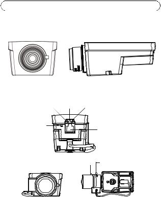
 Hardware overview
Focus puller Grip this part to adjust focus
AXIS M1103/M1104
Network |
Status |
Power |
LED |
LED |
LED |
Control |
|
Network |
button |
|
|
|
|
connector |
|
|
Iris connector |
|
|
(AXIS M1113/M1114) |
|
Zoom puller Focus puller |
|
AXIS M1113/M1114
Dimensions (HxWxD)
AXIS M1103/AXIS M1104 2.8 mm: 43 x 61 x 107 mm (1.7" x 2.4" x 4.2") AXIS M1103/AXIS M1104 6 mm: 43 x 61 x 110 mm (1.7" x 2.4" x 4.3") AXIS M1113: 43 x 61 x 140 mm (1.7" x 2.4" x 5.5")
AXIS M1114: 43 x 61 x 142 mm (1.7" x 2.4" x 5.6")

AXIS M11 Series |
Page 5 |
|
||
LED indicators |
|
|
|
|
LED |
Color |
Indication |
|
|
|
|
|
|
|
Network |
Green |
Steady for connection to a 100 Mbit/s network. Flashes |
|
|
|
|
for network activity. |
|
|
|
|
|
|
|
|
Amber |
Steady for connection to 10 Mbit/s network. Flashes for |
|
|
|
|
network activity. |
|
|
|
|
|
|
ENGLISH |
|
Unlit |
No network connection. |
|
|
|
|
|
|
|
|
|
Note: Configure the Status LED to be unlit during normal |
|
|
Status |
Green |
Steady green for normal operation. |
|
|
|
|
operation, or to flash only when the camera is accessed |
|
|
|
|
|
||
|
|
from Setup > System Options > LED. See the online help |
|
|
|
|
files for more information. |
|
|
|
|
|
|
|
|
Amber |
Steady during startup, reset to factory default or when |
|
|
|
|
restoring settings. |
|
|
|
|
|
|
|
|
Red |
Slow flash for failed upgrade. |
|
|
|
|
|
|
|
Power |
Green |
Normal operation. |
|
|
|
|
|
|
|
|
Amber |
Flashes green/amber during firmware upgrade. |
|
|
|
|
|
|
|
 Install the hardware
Important!
AXIS M11 Series is designed for indoor and outdoor use. To use the camera outdoors, install in an approved outdoor housing. Please see www.axis.com for more information on outdoor housings.
1.Attach the stand to the camera by screwing it on. For wall mounting, attach the stand to wall first, using 3 appropriate screws.
2.Attach the cable to the network connector (supports PoE class 1) in the camera.
3.Check that the indicator LEDs indicate the correct conditions. See table above.

Page 6 |
AXIS M11 Series |
 Assign an IP address
Most networks today have a DHCP server that automatically assigns IP addresses to connected devices. If your network does not have a DHCP server, the Network Camera will use 192.168.0.90 as the default IP address.
AXIS IP Utility and AXIS Camera Management are the recommended methods for setting an IP address in Windows. These free applications are available on the Axis Network Video Product CD supplied with this product, or they can be downloaded from www.axis.com/techsup Depending on the number of cameras you wish to install, use the method that suits you best.
Method |
Recommended for |
Operating system |
|
|
|
AXIS IP Utility |
Single camera |
Windows |
See page 7 |
Small installations |
|
|
|
|
AXIS Camera |
Multiple cameras |
Windows 2000 |
Management |
Large installations |
Windows XP Pro |
See page 8 |
Installation on a different |
Windows 2003 Server |
|
subnet |
Windows Vista |
|
|
Windows 7 |
|
|
|
Notes:
•If assigning the IP address fails, check that there is no firewall blocking the operation.
•For other methods of assigning or discovering the IP address of the AXIS M11 Series, such as in other operating systems, see page 12.

AXIS M11 Series |
Page 7 |
AXIS IP Utility - single camera/small installation
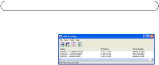
AXIS IP Utility automatically discovers and displays Axis devices on your network. You can also manually set a static IP
address through this application. AXIS IP Utility is available on the Axis Network Video Product CD, or it can be downloaded from www.axis.com/ techsup
Install the AXIS M11 Series Network Camera on the same network segment (physical subnet) as the computer running AXIS IP Utility.
Automatic discovery
1.Check that the AXIS M11 Series Network Camera is connected to the network and that power has been applied.
2.Start AXIS IP Utility.
3.When the AXIS M11 Series network camera appears in the window, double-click to open the camera’s home page.
4.See page 9 for instructions on how to set the password.
Set the IP address manually (optional)
1.Acquire an unused IP address on the same network segment your computer is connected to.
2.Select the AXIS M11 Series in the list.
3.Click the button  Assign new IP address to selected device and enter the IP address.
4.Click the Assign button and follow on-screen instructions. Note that the camera must be restarted within two minutes for the new IP address to be set.
5.Click the Home Page button to access the camera’s web pages.
6.See page 9 for instructions on how to set the password.
ENGLISH

Page 8 |
AXIS M11 Series |
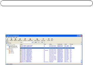
AXIS Camera Management - multiple cameras/large installations
AXIS Camera Management can automatically discover multiple Axis devices, show connection status, manage firmware upgrades and set IP addresses.
Automatic discovery
1.Check that the camera is connected to the network and that power has been applied.
2.Start AXIS Camera Management. When the camera appears in the window, right-click the link and select Live View Home Page.
3.See page 9 for instructions on how to set the password.
Assign an IP address in a single device
1.Select the network camera in AXIS Camera Management and click the Assign IP button  .
.
2.Select Assign the following IP address and enter the IP address, subnet mask and default router the device will use.
3.Click the OK button.

AXIS M11 Series |
Page 9 |
Assign IP addresses in multiple devices
AXIS Camera Management speeds up the process of assigning IP addresses to multiple devices, by suggesting IP addresses from a specified range.
1. |
Select the devices you wish to configure (different models can be |
|
|
|
selected) and click the Assign IP button |
. |
|
|
ENGLISH |
||
|
use. |
|
|
2. |
Select Assign the following IP address range and enter the range |
|
|
|
of IP addresses, the subnet mask and default router the devices will |
|
|
3. |
Click the OK button. |
|
|
|
|
||
 Set the password
To gain access to the product, the password for the default administrator user root must be set. This is done in the ‘Configure Root Password’ dialog, which is displayed when the AXIS M11 Series network camera is accessed for the first time.
To prevent network eavesdropping when setting the root password, this can be done via an encrypted HTTPS connection, which requires an HTTPS certificate (see note below).
To set the password via a standard HTTP connection, enter it directly in the first dialog shown below.
To set the password via an encrypted HTTPS connection, follow these steps:
1.Click the Create self-signed certificate button.
2.Provide the requested information and click OK. The certificate is created and the password can now be set securely. All traffic to and from the AXIS M11 Series is encrypted from this point on.

Page 10 |
AXIS M11 Series |
3.Enter a password and then re-enter to confirm the spelling. Click OK. The password has now been configured.
To create an HTTPS connection, start
 by clicking this button.
To configure the
password directly via an unencrypted connection, enter the password here.
4.To log in, enter the user name “root” in the dialog as requested Note: The default administrator user name ”root” cannot be deleted.
5.Enter the password as set above, and click OK.
If required, click Yes to install AMC (AXIS Media Control), which allows viewing of the video stream in Internet Explorer. You will need administrator rights on the computer to do this. If required, click the link to install missing decoders. The Live View page of the AXIS M11 Series network camera appears. The Setup link to the right gives you menu options that allow you to customize the camera.
AXIS M11 Series Page 11
 Adjust image and focus
To focus AXIS M1103/M1104: |
|
|
Unscrew the focus puller on the lens. Adjust the |
|
|
focus as required. Re-tighten the focus puller. |
|
|
Note: Grip the outer rim of the lens while focus- |
|
|
sing (see Hardware overview, on page 4). |
|
|
Gripping the whole lens could cause the |
Focus puller |
|
lens to come unscrewed. |
||
|
To focus AXIS M1113/M1114:
1.Click the Setup link at the top, right in the camera’s web interface and go to Basic Setup > Focus.
2.In the Focus Adjustment page set the DC-Iris to Disabled and click Save.
3.Unscrew the zoom puller on the lens by turning it anti-clockwise. Adjust the zoom setting as required. Re-tighten the zoom puller.
4.Unscrew the focus puller on the lens. Adjust the focus as required. Re-tighten the focus puller.
5.From the Focus Adjustment page, set the DC-Iris to Enabled and click Save.
Notes:
•The DC-Iris should always be disabled while focusing the camera. This opens the iris to its maximum, which gives the smallest depth of field and thus the best conditions for correct focusing. When the focus is set with this method it will then be maintained in all light conditions
•The design of AXIS M11 Series allows for slight lens movement to ensure sensor alignment.
Lens
Focus puller |
Zoom puller |
ENGLISH

Page 12 |
AXIS M11 Series |
Other methods of setting the IP address
|
Use in |
Notes |
|
operating |
|
|
system |
|
|
|
|
AVHS Service |
All |
To connect the camera to an AVHS service, |
Connection |
|
refer to the service provider´s Installation |
|
|
guide. For information and help to find a |
|
|
local AVHS Service Provider go to |
|
|
www.axis.com |
|
|
|
UPnP™ |
Windows |
When enabled on your computer, the camera |
|
(ME or |
is automatically detected and added to “My |
|
XP) |
Network Places.” |
|
|
|
Bonjour |
MAC OSX |
Applicable to browsers with support for |
|
(10.4 or |
Bonjour. Navigate to the Bonjour bookmark |
|
later) |
in your browser (e.g. Safari) and click on the |
|
|
link to access the camera’s web pages. |
|
|
|
AXIS Dynamic |
All |
A free service from Axis that allows you to |
DNS Service |
|
quickly and simply install your camera. |
|
|
Requires an Internet connection with no HTTP |
|
|
proxy. See www.axiscam.net for more |
|
|
information. |
|
|
|
ARP/Ping |
All |
See user’s manual. The command must be |
|
|
issued within 2 minutes of connecting power |
|
|
to the camera. |
|
|
|
DHCP |
All |
To view the admin pages for the network |
|
|
DHCP server, see the server’s documentation. |
|
|
|

AXIS M11 Series |
Page 13 |
Resetting to the Factory Default Settings
To reset all parameters and the IP address to Factory Default settings:
1. |
Disconnect power from the camera. |
|
|
2. |
Press and hold the Control button and reconnect power. |
|
|
3. |
Keep the Control button pressed for about 15 seconds until the |
|
|
|
Status indicator flashes amber. Release the Control button. |
|
|
|
ENGLISH |
||
4. |
When the Status indicator displays green (which can take up to 1 |
||
|
|||
|
minute) the process is complete and the camera has been reset. |
|
|
5. |
Re-assign the IP address. |
|
|
|
|
|
Accessing the camera from the Internet
Once installed, your AXIS M11 Series network camera is accessible on your local network (LAN). To access the camera from the Internet, configure network routers to allow incoming traffic, which is usually done on a specific port:
•HTTP port (default port 80) for viewing and configuration
•RTSP port (default port 554) for viewing H.264 video streams Please refer to the documentation for your router for further
instructions. For more information on this and other topics, visit the Axis Support Web at www.axis.com/techsup
Further information
The user’s manual is available from the Axis web site at www.axis.com or from the Axis Network Video Product CD supplied with this product.
Visit www.axis.com/techsup to check if there is updated firmware available for the AXIS M11 Series. To see the currently installed firmware version, see Setup > About in the camera’s web pages.
Série AXIS M11 |
Page 15 |
Guide d’installation de la caméra réseau Série AXIS M11
Ce guide est destiné à vous aider à installer la caméra réseau Série AXIS M11 sur votre réseau. Pour tout complément d’information, veuillez vous reporter au Manuel utilisateur présent sur le CD ou sur www.axis.com/ techsup
Procédure d’installation
1.Vérifiez le contenu de l’emballage par rapport à la liste ci-dessous.
2.Présentation du matériel. Voir page 16.
3.Installation du matériel. Voir page 18.
4.Attribution d’une adresse IP. Voir page 19.
Important !
Ce produit doit être utilisé conformément à la législation locale.
5.Configuration du mot de passe. Voir page 24.
6.Réglage de l’image et de la mise au point. Voir page 26
Contenu de l’emballage
Élément |
Titre/Variantes |
|
|
Caméra réseau |
AXIS M1103 |
|
AXIS M1104 |
|
AXIS M1113 |
|
AXIS M1114 |
|
|
Support de caméra |
|
|
|
CD |
CD du produit de vidéo sur IP AXIS, |
|
comprenant une documentation, des outils |
|
d’installation et des logiciels complémentaires |
|
|
Documentation |
Guide d’installation de la caméra réseau AXIS |
|
M1103/M1104/M1113/M1114 |
|
Garantie |
|
|
FRANÇAIS
Page 16 |
Série AXIS M11 |
 Description du matériel
Dispositif de mise au point |
Mainetenir cette partie pour ajuster le focus |
|||
|
|
|||
|
|
|
|
|
|
|
|
|
|
|
|
|
|
|
AXIS M1103/M1104
Voyant |
Voyant |
Voyant |
|
de réseau |
d'état |
d'alimentation |
|
Bouton de |
|
|
Connecteur |
commande |
|
|
|
|
|
réseau |
|
|
|
|
|
|
|
|
Connecteur pour l´Iris DC |
|
|
|
(AXIS M1113/M1114) |
|
Point zoom |
Dispositif de mise au point |
|
|
|
|
|
AXIS M1113/M1114
Dimensions (HxWxD)
AXIS M1103/AXIS M1104 2.8 mm: 43 x 61 x 107 mm (1.7" x 2.4" x 4.2") AXIS M1103/AXIS M1104 6 mm: 43 x 61 x 110 mm (1.7" x 2.4" x 4.3") AXIS M1113: 43 x 61 x 140 mm (1.7" x 2.4" x 5.5")
AXIS M1114: 43 x 61 x 142 mm (1.7" x 2.4" x 5.6")

Série AXIS M11 |
Page 17 |
|
||
Voyants lumineux |
|
|||
Voyant |
Couleur |
Indication |
|
|
|
|
|
|
|
Réseau |
Vert |
Continu en cas de connexion à un réseau de 100 Mbits/s. |
|
|
|
|
Clignote en cas d’activité réseau. |
|
|
|
|
|
|
|
|
Orange |
Continu en cas de connexion à un réseau de 10 Mbits/s. |
|
|
|
|
Clignote en cas d’activité réseau. |
|
|
|
|
|
|
|
|
Éteint |
Pas de connexion réseau. |
|
|
|
|
|
|
|
État |
Vert |
Vert continu en cas de fonctionnement normal. |
|
|
|
|
Remarque : le voyant d’état peut être configuré pour être |
|
|
|
|
éteint lors du fonctionnement normal, ou pour clignoter |
|
FRANÇAIS |
|
|
uniquement en cas d’accès à la caméra. Pour ce faire, |
|
|
|
|
cliquez sur Setup > System Options > LED |
|
|
|
|
(Configuration > Options système > Voyants). |
|
|
|
|
Reportez-vous à l’aide en ligne pour plus d’informations. |
|
|
|
|
|
||
|
|
|
|
|
|
Orange |
Continu pendant le démarrage, la réinitialisation des |
|
|
|
|
valeurs d’usine ou la restauration des paramètres. |
|
|
|
|
|
|
|
|
Rouge |
Clignote lentement en cas d’échec de la mise à niveau. |
|
|
|
|
|
|
|
Alimenta- |
Vert |
Fonctionnement normal. |
|
|
tion |
|
|
|
|
Orange |
Clignote en vert/orange pendant la mise à niveau des |
|
|
|
|
|
|
||
|
|
micrologiciels. |
|
|
|
|
|
|
|

Page 18 |
Série AXIS M11 |
 Installation du matériel
Important!
La série des caméras Série AXIS M11 est conçue pour une utilisation intérieure et extérieure. Pour pouvoir être utilisée à l’extérieur, la caméra doit être installé dans un caisson extérieur homologué. Consultez le site www.axis.com pour plus d’informations sur les caissons extérieur.
1.Vissez le support sur la caméra. Pour un montage mural, fixez d’abord le support sur le mur à l’aide de 3 vis adaptées.
2.Fixez le câble RJ-45 au connecteur réseau de la caméra (alimentation par Ethernet [PoE] classe 1 prise en charge).
3.Vérifiez que les voyants lumineux indiquent les bonnes conditions. Reportez-vous au tableau ci-dessus.
Série AXIS M11 |
Page 19 |
 Attribution d’une adresse IP
Aujourd’hui, la plupart des réseaux sont équipés d’un serveur DHCP qui attribue automatiquement des adresses IP aux périphériques connectés. Si votre réseau en est dépourvu, votre caméra réseau utilisera 192.168.0.90 comme adresse IP par défaut.
Si vous souhaitez définir une adresse IP statique sous Windows, nous recommandons l’utilisation de l’application AXIS IP Utility ou AXIS Camera Management. Ces deux applications gratuites sont disponibles sur le CD accompagnant votre produit de vidéo sur IP Axis. Vous pouvez également les télécharger à partir du site www.axis.com/techsup. Choisissez la méthode qui vous convient le mieux en fonction du nombre de caméras à installer.
Méthode |
Recommandée pour |
Système |
|
|
d’exploitation |
|
|
|
AXIS IP Utility |
Une seule caméra |
Windows |
Voir page 20 |
Petites installations |
|
|
|
|
AXIS Camera |
Plusieurs caméras |
Windows 2000 |
Management |
Grandes installations |
Windows XP Pro |
Voir page 22 |
Installation sur un autre |
Windows 2003 Server |
|
sous-réseau |
Windows Vista |
|
|
Windows 7 |
|
|
|
Notes:
•En cas d’échec de l’attribution d’adresse IP, vérifiez qu’aucun pare-feu ne bloque l’opération.
•Pour connaître les autres méthodes d’affectation ou de détection de l’adresse IP de votre caméra réseau Série AXIS M11, par exemple sous d’autres systèmes d’exploitation, reportez-vous à la page 28.
FRANÇAIS
Page 20 |
Série AXIS M11 |
AXIS IP Utility : une seule caméra/une petite installation
AXIS IP Utility recherche et affiche automatiquement les périphériques Axis présents sur votre réseau. Cette
application permet également de définir manuellement une adresse IP statique. Vous trouverez l’application AXIS IP Utility sur le CD accompagnant votre produit de vidéo sur IP Axis. Vous pouvez également la télécharger à partir du site www.axis.com/techsup.
Installez la caméra réseau Série AXIS M11 sur le même segment de réseau (sous-réseau physique) que celui de l’ordinateur exécutant l’application AXIS IP Utility.
Détection automatique
1.Vérifiez que la caméra réseau Série AXIS M11 est connectée au réseau et qu’elle est sous tension.
2.Lancez AXIS IP Utility.
3.Lorsque l’icône de la caméra réseau Série AXIS M11 apparaît dans la fenêtre, double-cliquez dessus pour ouvrir la page d’accueil correspondante.
4.Reportez-vous à la page 24 pour savoir comment configurer le mot de passe.
Configuration manuelle de l’adresse IP (facultatif)
1.Trouvez une adresse IP non utilisée sur le même segment de réseau que celui de votre ordinateur.
2.Sélectionnez Série AXIS M11 dans la liste.
3.Cliquez sur le bouton  Assign new IP address to selected device
(Attribuer une nouvelle adresse IP au périphérique sélectionné) et saisissez l’adresse IP.
Série AXIS M11 |
Page 21 |
4.Cliquez sur le bouton Assign (Attribuer) et suivez les instructions à l’écran. La caméra doit être redémarrée dans les deux minutes pour que la nouvelle adresse IP soit prise en compte.
5.Cliquez sur le bouton Home Page (Page d’accueil) pour accéder aux pages Web de la caméra.
6.Reportez-vous à la page 24 pour savoir comment configurer le mot de passe.
FRANÇAIS
Page 22 |
Série AXIS M11 |
AXIS Camera Management : plusieurs caméras/grandes installations
AXIS Camera Management est capable de détecter automatiquement plusieurs dispositifs Axis, d’afficher leur état de connexion, de gérer les mises à niveau des micrologiciels et de définir les adresses IP.
Détection automatique
1.Vérifiez que la caméra est connectée au réseau et qu’elle est sous tension.
2.Lancez AXIS Camera Management. Lorsque l’icône de la caméra apparaît dans la fenêtre, cliquez sur le lien à l’aide du bouton droit de la souris et sélectionnez Live View Home Page (Page d’accueil – Vidéo en direct).
3.Reportez-vous à la page 24 pour savoir comment configurer le mot de passe.
Attribution d’une adresse IP à un seul périphérique
1.Sélectionnez la caméra réseau dans l’application AXIS Camera Management, puis cliquez sur le bouton Assign IP (Attribuer une adresse IP). 
2.Sélectionnez Assign the following IP address (Attribuer l’adresse IP suivante) et saisissez l’adresse IP, le masque de sous-réseau et le routeur par défaut que le périphérique utilisera.
3.Cliquez sur le bouton OK.

Série AXIS M11 |
Page 23 |
Attribution d’adresses IP à plusieurs périphériques
AXIS Camera Management accélère le processus d’attribution d’adresses IP à plusieurs périphériques en suggérant des adresses IP dans une plage spécifiée.
1. Sélectionnez les périphériques à configurer (il peut s’agir de modèles différents), puis cliquez sur le bouton Assign IP (Attribuer adresses
IP)  .
.
2. |
Sélectionnez Assign the following IP address range (Attribuer la |
|
|
plage d'adresses IP suivante) et saisissez la plage d'adresses IP, le |
|
|
FRANÇAIS |
|
|
masque de sous-réseau et le routeur par défaut que les |
|
|
|
|
|
périphériques utiliseront. |
|
3. |
Cliquez sur OK. |
|
|
|
|

Page 24 |
Série AXIS M11 |
 Configuration du mot de passe
Pour accéder au produit, le mot de passe root de l’administrateur par défaut doit être configuré.Pour ce faire, utilisez la boîte de dialogue « Configure Root Password » (Configurer le mot de passe root) qui s’affiche lors du premier accès à la caméra réseau Série AXIS M11.
Pour éviter les écoutes électroniques lors de la configuration du mot de passe root, utilisez une connexion HTTPS cryptée nécessitant un certificat HTTPS (voir la remarque ci-dessous).
Pour configurer le mot passe avec une connexion HTTP standard, saisissez directement le mot de passe dans la première boîte de dialogue représentée ci-dessous.
Pour configurer le mot passe avec une connexion HTTPS cryptée, procédez comme suit :
1.Cliquez sur le bouton Create self-signed certificate (Créer un certificat autosigné).
2.Saisissez les informations demandées, puis cliquez sur OK. Le certificat est créé et le mot de passe peut maintenant être configuré en toute sécurité. L’ensemble du trafic entrant et sortant de la caméra réseau Série AXIS M11 est désormais crypté.

Série AXIS M11 |
Page 25 |
3.Saisissez un mot de passe, puis saisissez-le de nouveau pour confirmation. Cliquez sur OK. Le mot de passe est maintenant configuré.
Pour créer une connexion HTTPS, cliquez sur ce bouton.
Pour configurer
directement le mot de passe via une connexion cryptée, saisissez le mot de passe à cet endroit.
4.Pour vous connecter, saisissez le nom d’utilisateur « root » dans la boîte de dialogue à l’invite.
Remarque : le nom d’utilisateur « root » de l’administrateur par défaut ne peut pas être supprimé.
5.Saisissez le mot de passe tel que vous venez de le configurer et cliquez sur OK.
Si le système vous le demande, cliquez sur Yes (Oui) pour installer AMC (AXIS Media Control) afin de pouvoir visualiser les flux de données vidéo dans Internet Explorer. Pour ce faire, vous devrez être connecté à l’ordinateur avec des droits d’administrateur. Si nécessaire, cliquez sur le lien pour installer les décodeurs éventuellement manquants. La page Live View (Vidéo en direct) de la caméra réseau Série AXIS M11 s’affiche. Le lien Setup (Configuration) à droite contient toutes les options de menu nécessaires pour adapter la caméra à vos besoins.
FRANÇAIS
Loading...