


 Loading...
INSTALLATION GUIDE
AXIS 291 1U Video Server Rack
ESPAÑOL ITALIANO DEUTSCH AISÇFRAN ENGLISH

About This Document
This document describes how to install Axis blade video servers in the AXIS 291 1U Video Server Rack. Updated versions of this document will be available on the Axis Web site.
Intellectual Property Rights - Axis AB has intellectual property rights relating to technology embodied in the product described in this document. In particular, and without limitation, these intellectual property rights may include one or more of the patents listed at http://www.axis.com/patent.htm and one or more additional patents or pending patent applications in the US and other countries.
Liability - Every care has been taken in the preparation of this guide. Please inform your local Axis office of any inaccuracies or omissions. Axis Communications AB cannot be held responsible for any technical or typographical errors and reserves the right to make changes to the product and manuals without prior notice. Axis Communications AB makes no warranty of any kind with regard to the material contained within this document, including, but not limited to, the implied warranties of merchantability and fitness for a particular purpose.
Axis Communications AB shall not be liable nor responsible for incidental or consequential damages in connection with the furnishing, performance or use of this material.
Support Services - Should you require any technical assistance, please contact your Axis reseller. If your questions cannot be answered immediately, your reseller will forward your queries through the appropriate channels to ensure a rapid response. If you are connected to the Internet, you can:
•download user documentation and firmware updates
•find answers to resolved problems in the FAQ database. Search by product, category, or phrases
•report problems to Axis support staff by logging in to your private support area
Visit the Axis Support Web at www.axis.com/techsup
Electromagnetic Compatibility (EMC)
USA - This equipment generates, uses, and can radiate radio frequency energy and if not installed and used in accordance with the instruction manual, may cause interference to radio communications. It has been tested and found to comply with the limits for a Class B computing device pursuant to Subpart B of Part 15 of FCC rules, which are designed to provide reasonable protection against such interference when operated in a commercial environment. Operation of this equipment in a residential area is likely to cause interference, in which case the user at his/her own expense will be required to take whatever measures may be required to correct the interference. Shielded cables should be used with this unit to ensure compliance with the Class B limits.
Canada - This Class B digital apparatus complies with Canadian ICES-003.
Europe - This digital equipment fulfills the requirements for radiated emission according to limit B of EN55022:1998, and the requirements
for immunity according to EN55024:1998 residential, commercial, and light industry.
Japan - This is a class B product based on the standard of the Voluntary Control Council for Interference from Information Technology Equipment (VCCI). If this is used near a radio or television receiver in a domestic environment, it may cause radio interference. Install and use the equipment according to the instruction manual.
Australia - This electronic device meets the requirements of the Radio communications (Electromagnetic Compatibility) Standard 1998 AS/NZS 3548.
Please refer to this manual
for the selection of power cord.
Caution: Risk of electric shock. Disconnect AC power before internal service.

AXIS Video Server Rack Installation Guide |
Page 3 |
Axis Rack Mounted Video Server Solution
This installation guide describes the hardware installation of the AXIS 291 1U Video Server Rack, which can hold up to 3 Axis blade video servers. To install the Axis video server on the network, please see the video server’s own installation guide.
Hardware Inventory
Please contact your dealer if anything is missing or damaged.
Qty |
Item |
Models/variants/notes |
|
|
|
|
|
|
|
|
ENGLISH |
||||
|
|
|
|
|
|
|
|
1 |
Video server rack |
AXIS 291 1U Video Server Rack |
|
|
|
||
|
|
|
|
||||
|
|
|
|
|
|
|
|
2 |
Cover plates |
Front panel cover 1U |
|
|
|
|
|
|
|
|
|
|
|
|
|
1 |
AC power cord |
• |
Europe |
• |
Switzerland |
|
|
|
|||||||
|
|
• |
UK |
• |
Denmark |
|
|
|
|
• |
US, Canada, Japan |
• |
South korea |
|
|
|
|
• |
Australia |
|
|
|
|
|
|
|
|
|
|
|
|
1 |
Warranty Document |
|
|
|
|
|
|
|
|
|
|
|
|
|
|
1 |
Mounting kit |
See separate inventory below |
|
|
|
|
|
|
|
|
|
|
|
|
|
Power cord plug variants
Country |
Europe |
UK |
US, |
Australia |
Switzerland |
Denmark |
South |
|
|
|
Canada, |
|
|
|
Korea |
|
|
|
Japan |
|
|
|
|
|
|
|
|
|
|
|
|
Power |
|
|
|
|
|
|
|
cord plug |
|
|
|
|
|
|
|
|
|
|
|
|
|
|
|
Mounting kit
Please contact your dealer if anything is missing or damaged.
Qty |
Item |
Models/variants/notes |
|
|
|
4 |
Rubber foot |
For placement on flat surfaces |
|
|
|
1 |
Mounting bracket (side) |
Left |
|
|
|
1 |
Mounting bracket (side) |
Right |
|
|
|
8 |
M3x8 screw (recessed) |
For attachment of side brackets |
|
|
|
4 |
M6x20 screw |
For mounting AXIS Video Server |
|
|
Rack in equipment rack |
|
|
|
3 |
Terminal connector |
12-pin, green |
|
block |
|
|
|
|
Note:
The 2 mounting brackets included in the mounting kit are slightly different. See the label on each bracket.

Page 4 |
AXIS Video Server Rack Installation Guide |
AXIS 291 1U Video Server Rack - Overview
Read the following information to familiarize yourself with the AXIS 291 1U Video Server Rack, making note of where the connectors and indicators are located.
Power |
|
|
|
I/O Terminal |
|
|
|
|
|
|
|
|
|
|
|
|
|
|
|
|
|
I/O Terminal |
|
|
|
|
|
|
|
|
|
|
I/O Terminal |
|
|
|
Power & Network |
|
|
|
|
Network |
|
||||||||||||||||||||||||||||||||||||||||||||||||
Connector |
|
|
|
Connector 3 |
|
|
|
|
|
|
|
|
|
|
|
|
|
|
|
|
|
Connector 2 |
|
|
|
|
|
|
|
|
|
|
Connector 1 |
|
|
|
LEDs |
|
|
|
|
Connector |
|
||||||||||||||||||||||||||||||||||||||||||||||||
|
|
|
|
|
|
|
|
|
|
|
|
|
|
|
|
|
|
|
|
|
|
|
|
|
|
|
|
|
|
|
|
|
|
|
|
|
|
|
|
|
|
|
|
|
|
|
|
|
|
|
|
|
|
|
|
|
|
|
|
|
|
|
|
|
|
|
|
|
|
|
|
|
|
|
|
|
|
|
|
|
|
|
|
|
|
|
|
|
|
|
|
|
|
|
|
|
|
|
|
|
|
|
|
|
|
|
|
|
|
|
|
|
|
|
|
|
|
|
|
|
|
|
|
|
|
|
|
|
|
|
|
|
|
|
|
|
|
|
|
|
|
|
|
|
|
|
|
|
|
|
|
|
|
|
|
|
|
|
|
|
|
|
|
|
|
|
|
|
|
|
|
|
|
|
|
|
|
|
|
|
|
|
|
|
|
|
|
|
|
|
|
|
|
|
|
|
|
|
|
|
|
|
|
|
|
|
|
|
|
|
|
|
|
|
|
|
|
|
|
|
|
|
|
|
|
|
|
|
|
|
|
|
|
|
|
|
|
|
|
|
|
|
|
|
|
|
|
|
|
|
|
|
|
|
|
|
|
|
|
|
|
|
|
|
|
|
|
|
|
|
|
|
|
|
|
|
|
|
|
|
|
|
|
|
|
|
|
|
|
|
|
|
|
|
|
|
|
|
|
|
|
|
|
|
|
|
|
|
|
|
|
|
|
|
|
|
|
|
|
|
|
|
|
|
|
|
|
|
|
|
|
|
|
|
|
|
|
|
|
|
|
|
|
|
|
|
|
|
|
|
|
|
|
|
|
|
|
|
|
|
|
|
|
|
|
|
|
|
|
|
|
|
|
|
|
|
|
|
|
|
|
|
|
|
|
|
|
|
|
|
|
|
|
|
|
|
|
|
|
|
|
|
|
|
|
|
|
|
|
|
|
|
|
|
|
|
|
|
|
|
|
|
|
|
|
|
|
|
|
|
|
|
|
|
|
|
|
|
|
|
|
|
|
|
|
|
|
|
|
|
|
|
|
|
|
|
|
|
|
|
|
|
|
|
|
|
|
|
|
|
|
|
|
|
|
|
|
|
|
|
|
|
|
|
|
|
|
|
|
|
|
|
|
|
|
|
|
|
|
|
|
|
|
|
|
|
|
|
|
|
|
|
|
|
|
|
|
|
|
|
|
|
|
|
|
|
|
|
|
|
|
|
|
|
|
|
|
|
|
|
|
|
|
|
|
|
|
|
|
|
|
|
|
|
|
|
|
|
|
|
|
|
|
|
|
|
|
|
|
|
|
|
|
|
|
|
|
|
|
|
|
|
|
|
|
|
|
|
|
|
|
|
|
|
|
|
|
|
|
|
|
|
|
|
|
|
|
|
|
|
|
|
|
|
|
|
|
|
|
|
|
|
|
|
|
|
|
|
|
|
|
|
|
|
|
|
|
|
|
|
|
|
|
|
|
|
|
|
|
|
|
|
|
|
|
|
|
|
|
|
|
|
|
|
|
|
|
|
|
|
|
|
|
|
|
|
|
|
|
|
|
|
|
|
|
|
|
|
|
|
|
|
|
|
|
|
|
|
|
|
|
|
|
|
|
|
|
|
|
|
|
|
|
|
|
|
|
|
|
|
|
|
|
|
|
|
|
|
|
|
|
|
|
|
|
Power Connector - Input power: 100-240V AC, 50-60 Hz, 1.9A
I/O Terminal Connector(s) - provides the physical interface to the functions supported by the Axis blade video server. For more information see page 8.
Power & Network LEDs - The 10/100 LED flashes red for 10 Mbit, and flashes green for 100 Mbit. The 1000 LED flashes green for 1 Gbit. The power LED shows steady green when the rack is powered.
Network Connector - Axis blade video servers are designed for 10/100/1000 Mbps networks and are connected via a standard RJ-45 connector.
Placement requirements
The location the AXIS 291 1U Video Server Rack is used in must meet the following requirements:
•Ambient temperature: 0° to +45°C (32° to 113°F)
•Relative humidity: 20-80%
•Power source within 1.8 meters
•Minimum 5cm free space on each side, to ensure adequate ventilation
•No excessive dust
Placement on a shelf/table
1. Attach the 4 rubber feet to the underside of the unit, as illustrated here.
2. Place on a flat surface. Note that the AXIS Video Server Rack with cables weighs up to 6kg. Check that the surface can support this weight.

AXIS Video Server Rack Installation Guide |
Page 5 |
Installation in a 19” equipment rack
Requirements
•Pozidriv screwdriver #1
•Pozidriv screwdriver #3
•The rack must be braced and bolted to the floor.
•The AXIS Video Server Rack must be grounded to the same ground as the equipment rack.
When mounting the AXIS Video Server Rack in a rack, never stack other units directly on top - the mounting brackets are not designed to support more than 1 unit. Each unit in the rack must be secured with appropriate brackets. Place the heaviest units at the bottom of the rack.
Attaching the brackets
The 2 mounting brackets are slightly different. To tell these apart, see the label on each bracket. See also the illustration on page 3.
1. Remove the screw shown here from each side of the unit. These will be replaced by the screws used to fasten the bracket.
2. Using the recessed M3X8 screws, fasten the bracket to the side of the unit. Do not use the screw that was removed in step 1.
3. Slide the AXIS Video Server Rack into the equipment rack. Insert the M6X20 screws and tighten.
ENGLISH

Page 6 |
AXIS Video Server Rack Installation Guide |
Connect power
The AXIS Video Server Rack has no On/Off switch or button and will power up as soon as the power cord is connected. Detaching the cord is the only way to remove power, so it is important to locate the unit so that the power cord is easily accessible. Please ensure that the correct AC power cord for your country is used.
Note also the following requirements and restrictions:
•To prevent the risk of electrical shock when in contact with the unit casing, only earthed/ grounded power cords should be used to power the AXIS Video Server Rack.
•Protection against overcurrents, short circuits and earth faults should be provided in the building installation.
•The AXIS Video Server Rack is intended for indoor use only, and only for TN and IT power systems.
•The AXIS 291 Video Server Rack is designed for use with Axis Blade Video Servers only.
•If a foreign object is accidently dropped into the Video Server Rack, always disconnect power before attempting to remove the object.
Power specifications
•Input voltage 100-240V AC, at 50/60Hz
•Input current: 1.9A
•Power consumption with 3 x AXIS 243Q: Max 80W

AXIS Video Server Rack Installation Guide |
Page 7 |
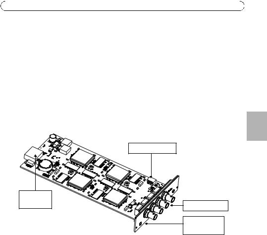
AXIS blade video servers
S/N - (serial number) is identical to the unit’s MAC/Ethernet address, e.g. 00408C1A2B3C = 00-40-8C-1A-2B-3C.
P/N - is the product’s model number.
Bus Connector - This is the physical interface to the I/O terminal connector on the rack.
DIP Switches (4-port models) - Each video input has a corresponding line termination DIP switch. Axis blade video servers are supplied with the line termination enabled for each input; i.e. with the DIP switches set to ON (down position). To connect the video server in parallel with other equipment, disable the input termination by setting the corresponding DIP switch to OFF (up position). Failure to do so may affect the image quality negatively.
DIP Switches
Bus
Connector
4 Video inputs
S/N & P/N label
DIP Switches (1-port models) - These models can accommodate either composite or Y/C video. The type to use is determined by the DIP switch settings. 1-port AXIS blade video servers are supplied configured for composite video input, as shown in the table below.
Switch |
1 |
2 |
3 |
4 |
|
|
|
|
|
Description |
75 ohm video in |
75 ohm video out |
Connects video in |
Not used |
|
termination |
termination |
and video out |
|
|
|
|
|
|
Composite video |
on |
off |
on |
n/a |
input |
|
|
|
|
|
|
|
|
|
Y/C video input |
on |
on |
off |
n/a |
|
|
|
|
|
ENGLISH
Page 8 |
AXIS Video Server Rack Installation Guide |
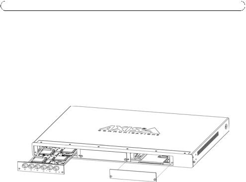
Mounting AXIS blade video servers
The AXIS Video Server Rack can accommodate 3 Axis blade video servers. The slots for these are numbered 1-3 from left to right, as seen from the front. The I/O connectors for each slot on the rear panel are also numbered.
1.Remove a front panel cover from the slot in which the video server will be mounted. This is done by unfastening the screw on each side of the cover.
2.Slide the video server into place, using the guides as an aid. The dip switch for setting the line termination should be visible on the top edge.
3.Fix the video server in place, using the screws from the front panel cover.
Note: Leaving an empty slot on the AXIS Video Server Rack open is not permitted. Front panel covers must be used on all empty slots.
The I/O Terminal connector
The AXIS Video Server Rack server provides an I/O terminal connector for each Axis blade video server (see illustration on page 4). This is used for connecting external equipment, in applications for e.g. motion detection, event triggering, time lapse recording, alarm notification via email, image storage to FTP locations, etc.

AXIS Video Server Rack Installation Guide |
Page 9 |
Connector interfaces
The interfaces available via the 12-pin I/O terminal connector are as follows:
• 4 Digital inputs - used for e.g. a pushbutton. If the button is pressed, the state changes and the input will be active (shown under Event Configuration > Port Status). (AXIS 241Q Blade, AXIS 241S Blade, AXIS 243Q, AXIS 240Q)
• 4 Transistor outputs - for e.g. alarm devices that can be activated from Output buttons on the Live View page, or as an action to an Event Type. The output will show as active
|
(in Event Configuration > Port Status) if the device is activated. |
|
|||||
|
• 10 configurable I/O connectors (AXIS Q7406) |
|
|
|
|||
|
|
|
ENGLISH |
||||
|
• RS-485 interface, for e.g. Pan/Tilt/Zoom devices (see www.axis.com for drivers) |
||||||
|
|
||||||
|
• Auxiliary power |
|
|
|
|
|
|
Connector pinout |
|
|
|
|
|
|
|
|
|
|
|
|
|
||
|
|
|
|
|
|
|
|
Pin |
AXIS Q7406 |
|
AXIS 243Q |
|
AXIS 241Q Blade, |
|
|
|
|
|
|
|
AXIS 241S Blade, AXIS 240Q |
|
|
|
|
|
|
|
|
|
|
1 |
+12V out, 100mA |
|
+12V out, 100mA |
+12V out, 100mA |
|
|
|
|
|
|
|
|
|
|
|
2 |
GND |
|
GND |
|
GND |
|
|
|
|
|
|
|
|
|
|
3 |
Channel 1, Configurable |
I/O 1 |
Channel 1, |
Input 1 |
Input1 |
|
|
|
|
|
|
|
|
|
|
4 |
Channel 2, Configurable |
I/O 1 |
Channel 2, |
Input 1 |
Input 2 |
|
|
|
|
|
|
|
|
|
|
5 |
Channel 3, Configurable |
I/O 1 |
Channel 3, |
Input 1 |
Input 3 |
|
|
|
|
|
|
|
|
|
|
6 |
Channel 4, Configurable |
I/O 1 |
Channel 4, |
Input 1 |
Input 4 |
|
|
|
|
|
|
|
|
|
|
7 |
Channel 5, Configurable |
I/O 1 |
Channel 1, |
Input 1 |
Output1 |
|
|
|
|
|
|
|
|
|
|
8 |
Channel 6, Configurable |
I/O 2 |
Channel 2, |
Input 1 |
Output2 |
|
|
|
|
|
|
|
|
|
|
9 |
Channel 1, Configurable |
I/O 2 |
Channel 3, |
Input 1 |
Output3 |
|
|
|
|
|
|
|
|
|
|
10 |
Channel 2, Configurable |
I/O 2 |
Channel 4, |
Input 1 |
Output4 |
|
|
|
|
|
|
|
|
|
|
11 |
Channel 1, RS485A |
|
Channel 1, RS485A |
RS485A |
|
|
|
|
|
|
|
|
|
|
|
12 |
Channel 1, RS485B |
|
Channel 1, RS485B |
RS485B |
|
|
|
|
|
|
|
|
|
|
|
To connect input/output devices to the I/O terminal connector:
1.Referring to the table above, loosen the corresponding screw on top of the pin on the green connector block.
2.Push the cable into the connector block and secure it by fastening the screw.
3.Once all devices are connected, push the connector block into the terminal connector on the rear panel of the AXIS Video Server Rack.
For compatible replacement connectors, contact http://www.phoenixcontact.com, quoting: MC1.5/ 12-ST-3.81 (art no 1803675).
Baie de serveur vidéo AXIS Installation Guide |
Page 11 |
Serveur vidéo Axis pour montage sur baie (rack)
Ce Guide d'installation décrit l'installation de la baie de serveur vidéo AXIS pouvant accueillir trois serveurs vidéo Axis Blade. Pour installer le serveur vidéo Axis sur le réseau, consultez le Guide d'installation du serveur vidéo.
Matériel
Contactez votre revendeur si un élément est manquant ou endommagé.
Qté |
Article |
Modèles/variantes/remarques |
|
|
|
|
|
|
|
|
|
|
|
|
|
1 |
Baie du serveur vidéo |
Baie de serveur vidéo 1U AXIS 291 |
|
|
|
|
|
|
|
|
|
|
|
|
|
2 |
Plaques du capot |
Capot du panneau frontal 1U |
|
|
|
|
|
|
|
|
AISÇFRAN |
||||
|
|
|
|
|
|
|
|
1 |
Câble d'alimentation |
• |
Europe |
• |
Suisse |
|
|
|
|
||||||
|
|
• |
Royaume-Uni |
• |
Danemark |
|
|
|
|
• |
États-Unis, Canada, Japon |
• |
Corée du Sud |
|
|
|
|
• |
Australie |
|
|
|
|
|
|
|
|
|
|
||
|
|
|
|
|
|
|
|
1 |
Document de garantie |
|
|
|
|
|
|
|
|
|
|
|
|
|
|
1 |
Kit de montage |
Voir l'inventaire ci-dessous |
|
|
|
|
|
|
|
|
|
|
|
|
|
Variantes de prise du câble d'alimentation
Pays |
Europe |
Royaume |
États-Unis, |
Australie |
Suisse |
Danemark |
Corée |
|
|
-Uni |
Canada, |
|
|
|
du Sud |
|
|
|
Japon |
|
|
|
|
|
|
|
|
|
|
|
|
Prise du |
|
|
|
|
|
|
|
câble |
|
|
|
|
|
|
|
d'aliment- |
|
|
|
|
|
|
|
ation |
|
|
|
|
|
|
|
|
|
|
|
|
|
|
|
Kit de montage - contactez votre revendeur si un élément est manquant ou endommagé.
Qté |
Article |
Modèles/variantes/remarques |
Remarque |
|
|
4 |
Pied en caoutchouc |
Pour installation sur des |
|
|
|
|
|
surfaces planes |
|
|
|
1 |
Support de montage |
Gauche |
|
|
|
|
(latéral) |
|
|
|
|
1 |
Support de montage |
Droite |
|
|
|
|
(latéral) |
|
Gauche |
Droite |
|
8 |
Vis M3x8 (à tête à |
Pour fixation des supports |
|||
|
|
||||
|
empreinte) |
latéraux |
Les deux supports de montage |
||
|
|
|
|||
4 |
Vis M6x20 |
Pour montage de la baie de |
inclus dans le kit de montage sont |
||
|
|
serveur vidéo AXIS sur baie |
légèrement différents. Consultez les |
||
3 |
Connecteur pour |
12 broches, vert |
étiquettes sur chaque support. |
||
|
terminaux |
|
|
|
|

Page 12 |
Baie de serveur vidéo AXIS Installation Guide |
Baie de serveur vidéo 1U AXIS 291 - Présentation
Lisez les consignes suivantes pour vous familiariser avec la baie de serveur vidéo AXIS en repérant les connecteurs et les témoins.
|
|
|
|
|
|
|
|
|
|
|
|
|
|
|
|
|
|
|
|
|
|
|
|
|
|
|
|
|
|
|
|
|
|
|
|
|
|
|
|
|
|
|
|
|
|
|
|
|
|
|
|
|
|
|
|
|
|
|
|
|
|
|
|
|
|
|
|
|
|
|
|
|
|
|
|
|
|
|
Témoins DEL |
|
|
|
|
|
|
|
|
|
|
||||||||||
Connecteur |
|
|
|
|
|
Connecteur pour |
|
|
|
|
|
|
|
Connecteur pour |
|
|
|
|
|
|
|
Connecteur pour |
|
d'alimentation et de |
|
|
Connecteur |
||||||||||||||||||||||||||||||||||||||||||||||||||||||||||||||||||||||||
d'alimentation |
|
|
|
|
terminaux E/S 3 |
|
|
|
|
|
|
|
terminaux E/S 2 |
|
|
|
|
|
|
|
terminaux E/S 1 |
|
réseau |
|
|
de réseau |
|||||||||||||||||||||||||||||||||||||||||||||||||||||||||||||||||||||||||
|
|
|
|
|
|
|
|
|
|
|
|
|
|
|
|
|
|
|
|
|
|
|
|
|
|
|
|
|
|
|
|
|
|
|
|
|
|
|
|
|
|
|
|
|
|
|
|
|
|
|
|
|
|
|
|
|
|
|
|
|
|
|
|
|
|
|
|
|
|
|
|
|
|
|
|
|
|
|
|
|
|
|
|
|
|
|
|
|
|
|
|
|
|
|
|
|
|
|
|
|
|
|
|
|
|
|
|
|
|
|
|
|
|
|
|
|
|
|
|
|
|
|
|
|
|
|
|
|
|
|
|
|
|
|
|
|
|
|
|
|
|
|
|
|
|
|
|
|
|
|
|
|
|
|
|
|
|
|
|
|
|
|
|
|
|
|
|
|
|
|
|
|
|
|
|
|
|
|
|
|
|
|
|
|
|
|
|
|
|
|
|
|
|
|
|
|
|
|
|
|
|
|
|
|
|
|
|
|
|
|
|
|
|
|
|
|
|
|
|
|
|
|
|
|
|
|
|
|
|
|
|
|
|
|
|
|
|
|
|
|
|
|
|
|
|
|
|
|
|
|
|
|
|
|
|
|
|
|
|
|
|
|
|
|
|
|
|
|
|
|
|
|
|
|
|
|
|
|
|
|
|
|
|
|
|
|
|
|
|
|
|
|
|
|
|
|
|
|
|
|
|
|
|
|
|
|
|
|
|
|
|
|
|
|
|
|
|
|
|
|
|
|
|
|
|
|
|
|
|
|
|
|
|
|
|
|
|
|
|
|
|
|
|
|
|
|
|
|
|
|
|
|
|
|
|
|
|
|
|
|
|
|
|
|
|
|
|
|
|
|
|
|
|
|
|
|
|
|
|
|
|
|
|
|
|
|
|
|
|
|
|
|
|
|
|
|
|
|
|
|
|
|
|
|
|
|
|
|
|
|
|
|
|
|
|
|
|
|
|
|
|
|
|
|
|
|
|
|
|
|
|
|
|
|
|
|
|
|
|
|
|
|
|
|
|
|
|
|
|
|
|
|
|
|
|
|
|
|
|
|
|
|
|
|
|
|
|
|
|
|
|
|
|
|
|
|
|
|
|
|
|
|
|
|
|
|
|
|
|
|
|
|
|
|
|
|
|
|
|
Connecteur d'alimentation - Alimentation en entrée : 100-240 Vca, 50-60 Hz, 1,9 A
Connecteur(s) pour terminaux E/S : fait/font office d'interface physique pour les fonctions prises en charge par le serveur vidéo Axis Blade. Pour plus d'informations, reportez-vous à la page 16.
Témoins DEL d'alimentation et de réseau : le témoin DEL 10/100 clignote en rouge pour les réseaux de 10 Mbits/s et en vert pour ceux de 100 Mbits/s. Le témoin DEL 1000 clignote en vert pour les réseaux de 1 Gbit/s. Le témoin DEL d'alimentation reste allumé en vert si la baie est sous tension.
Connecteur de réseau : les serveurs vidéo Axis Blade sont conçus pour les réseaux de 10/100/1 000 Mbit/s. La connexion s'effectue via un connecteur RJ-45 standard.
Consignes pour l'installation
La pièce où sera installé la baie de serveur vidéo AXIS doit respecter les critères suivants :
•Température ambiante : de 0 °C à +45 °C (de 32 °F à 113 °F)
•Humidité relative : 20-80%
•La source d'alimentation doit se trouver à moins de 1,80 m.
•Espace minimum de 5 cm sur les côtés afin de garantir une ventilation efficace
•Pas trop de poussière
Installation sur une étagère ou une table
1. Fixez les quatre pieds en caoutchouc sous l'appareil, comme sur l'illustration.
2. Placez l'appareil sur une surface plane. Notez que la baie de serveur vidéo AXIS et les câbles peuvent peser jusqu'à 6 kg. Vérifiez si la surface peut supporter ce poids.

Baie de serveur vidéo AXIS Installation Guide |
Page 13 |
Installation sur baie de 19" (48 cm)
Matériel nécessaire
•Tournevis Pozidriv n°1
•Tournevis Pozidriv n°3
•La baie doit être fixée et boulonnée au sol.
•La baie de serveur vidéo AXIS doit être relié à la même prise de terre que la baie.
Lors de l'installation de la baie de serveur vidéo AXIS sur une baie, ne placez jamais d'autres unités sur celui-ci. Les supports de montage ne peuvent supporter qu'une seule unité. Chaque unité de la baie doit être fixée à l'aide de supports adéquats. Placez les unités les plus lourdes au bas de la baie.
Fixation des supports
Les deux supports de montage sont légèrement différents. Pour les différencier, consultez l'étiquette sur chaque support. Consultez l'illustration à la page 11.
1. Retirez la vis placée de chaque côté de l'unité (voir illustration). Ces vis seront remplacées par celles qui permettront de fixer le support.
2.À l'aide des vis à tête à empreinte M3X8, fixez le support sur le côté
de l'unité. N'utilisez pas la vis retirée à l'étape 1.
3. Glissez la baie de serveur vidéo AXIS dans la baie. Placez les vis M6X20 et serrez-les.
AISÇFRAN

Page 14 |
Baie de serveur vidéo AXIS Installation Guide |
Branchement
La baie de serveur vidéo AXIS ne dispose d'aucun interrupteur ou bouton ON/OFF (Marche/Arrêt). Il est donc allumé dès que le câble d'alimentation est branché. Vous ne pourrez éteindre l'appareil qu'en débranchant le câble. Placez-le de façon à ce que le câble soit facilement accessible. Veillez à utiliser le câble d'alimentation adapté au pays où vous vous trouvez.
Veuillez noter les consignes et les restrictions suivantes :
•Pour éviter tout risque d'électrocution en cas de contact avec le boîtier de l'appareil, n'utilisez que des câbles d'alimentation avec prise de terre pour alimenter la baie de serveur vidéo AXIS.
•Le bâtiment où l'appareil sera installé doit disposer d'un système de protection contre les surtensions, les courts-circuits et les défauts à la terre.
•La baie de serveur vidéo AXIS ne peut être utilisé qu'à l'intérieur. Il est conçu uniquement pour les systèmes électriques TN et IT.
•La baie de serveur vidéo AXIS 291 est conçue pour une utilisation avec les serveurs vidéo Axis Blade uniquement.
•Si vous souhaitez récupérer un corps étranger qui se serait glissé dans la baie de serveur vidéo, débranchez toujours l'appareil au préalable.
Données électriques
•Tension d'entrée : 100-240 Vca à 50/60 Hz
•Courant à l'entrée : 1,9 A
•Consommation avec trois serveurs AXIS 243Q : jusqu'à 80 W
Baie de serveur vidéo AXIS Installation Guide |
Page 15 |
Serveurs vidéo AXIS Blade
S/N - (numéro de série) identique à l'adresse MAC/Ethernet de l'unité, par ex. 00408C1A2B3C = 00-40-8C-1A-2B-3C.
P/N - référence du modèle du produit.
Connecteur de bus - interface physique vers le connecteur pour terminaux E/S sur la baie.
Interrupteurs DIP (modèles à 4 ports) - À chaque entrée vidéo correspond un interrupteur DIP de terminaison de ligne. Sur les serveurs vidéo Axis Blade, la terminaison de ligne de chaque entrée est activée. Autrement dit, les interrupteurs DIP sont en position ON (vers le bas). Pour connecter l'entrée vidéo en parallèle avec un autre équipement, vous devez désactiver la terminaison d'entrée en mettant l'interrupteur DIP correspondant en position OFF (vers le haut). Si vous ne procédez pas à cette modification, la qualité de l'image peut s'en ressentir.
Interrupteurs DIP
AISÇFRAN
Connecteur |
|
de bus |
4 entrées vidéo |
|
Étiquette S/N et P/N
Interrupteurs DIP (modèles à 1 port) - Ces modèles sont compatibles avec la vidéo composite ou S-vidéo. Le mode est défini par les paramètres de l'interrupteur DIP. Les serveurs vidéo AXIS Blade à un port sont configurés pour l'entrée vidéo composite comme le montre le tableau ci-dessous.
.
Commutateur |
1 |
2 |
3 |
4 |
|
|
|
|
|
Description |
entrée vidéo 75 ohms |
sortie vidéo 75 ohms |
Raccordement entrée |
Non utilisé |
|
terminaison |
terminaison |
et sortie vidéo |
|
|
|
|
|
|
Entrée vidéo |
activé |
désactivé |
activé |
ne s'applique pas |
composite |
|
|
|
|
|
|
|
|
|
Entrée S-vidéo |
activé |
activé |
désactivé |
ne s'applique pas |
|
|
|
|
|

Page 16 |
Baie de serveur vidéo AXIS Installation Guide |
Montage des serveurs vidéo AXIS Blade
La baie de serveur vidéo AXIS peut accueillir trois serveurs vidéo Axis Blade. Les fentes sont numérotées de 1 à 3 et de gauche à droite sur le panneau frontal. Les connecteurs E/S pour chaque fente situés à l'arrière de l'unité sont également numérotés.
1.Retirez le capot du panneau frontal de l'emplacement qui accueillera le serveur vidéo. Pour ce faire, dévissez la vis située de chaque côté du capot.
2.Placez le serveur vidéo en vous aidant des guides. L'interrupteur DIP de terminaison de ligne doit être visible sur la partie supérieure.
3.Fixez le serveur vidéo à l'aide des vis du capot du panneau frontal.
Note:
Il n'est pas permis de laisser une fente libre sur la baie de serveur vidéo AXIS.
Les capots du panneau frontal doivent être placés sur tous les emplacements libres.
Connecteur pour terminaux E/S
La baie de serveur vidéo AXIS dispose d'un connecteur pour terminaux E/S pour chaque serveur vidéo Axis Blade (voir illustration en page 12). Cela permet d'y relier du matériel externe pour la détection de mouvement, le déclenchement d'événements, l'enregistrement à intervalles, les notifications d'alarme par e-mail, l'enregistrement d'images sur les sites FTP, etc.
Loading...