


 Loading...
INSTALLATION GUIDE
AXIS Q60 Series
AXIS Q6032 PTZ Dome Network Camera AXIS Q6034 PTZ Dome Network Camera AXIS Q6035 PTZ Dome Network Camera
ESPAÑOL ITALIANO DEUTSCH AISÇFRAN ENGLISH

Legal Considerations
Video and audio surveillance can be prohibited by laws that vary from country to country. Check the laws in your local region before using this product for surveillance purposes.
This product includes one (1) H.264 decoder license. To purchase further licenses, contact your reseller.
Trademark Acknowledgments
Apple, Boa, Bonjour, Ethernet, Internet Explorer, Linux, Microsoft, Mozilla, Netscape Navigator, OS/2, Real, SMPTE, QuickTime, UNIX, Windows, WWW are registered trademarks of the respective holders. Java and all Java-based trademarks and logos are trademarks or registered trademarks of Sun Microsystems, Inc. in the United States and other countries. Axis Communications AB is independent of Sun Microsystems Inc. UPnP™ is a certification mark of the UPnP™ Implementers Corporation.
Electromagnetic Compatibility (EMC)
This equipment generates, uses and can radiate radio frequency energy and, if not installed and used in accordance with the instructions, may cause harmful interference to radio communications. However, there is no guarantee that interference will not occur in a particular installation.
If this equipment does cause harmful interference to radio or television reception, which can be determined by turning the equipment off and on, the user is encouraged to try to correct the interference by one or more of the following measures: Re-orient or relocate the receiving antenna. Increase the separation between the equipment and receiver. Connect the equipment to an outlet on a different circuit to the receiver. Consult your dealer or an experienced radio/TV technician for help. Shielded (STP) network cables must be used with this unit to ensure compliance with EMC standards.
USA - This equipment has been tested and found to comply with the limits for a Class B computing device pursuant to Subpart B of Part 15 of FCC rules, which are designed to provide reasonable protection against such interference when operated in a commercial environment. Operation of this equipment in a residential area is likely to cause interference, in which case the user at his/her own expense will be required to take whatever measures may be required to correct the interference.
Canada - This Class B digital apparatus complies with Canadian ICES-003.
Europe - This digital equipment fulfills the requirements for RF emission according to limit B of EN 55022. This product fulfills the requirements for immunity according to EN 61000-6-2 industrial enviroments and EN 55024.
Japan - This is a class B product based on the standard of the Voluntary Control Council for Interference from Information Technology Equipment (VCCI). If this is used near a radio or television receiver in a domestic environment, it may cause radio interference. Install and use the equipment according to the instruction manual.
Australia - This electronic device meets the requirements of the Radio communications (Electromagnetic Compatibility) Standard AS/NZS CISPR22:2002.
Korea - |
|
% |
|
|
|
|
|
|
|
|
|
|
|
|
|
|
|
|
|
|
Safety
Complies to EN 60950-1 (IEC 60950-1), Safety of Information Technology Equipment.
Equipment Modifications
This equipment must be installed and used in strict accordance with the instructions given in the user documentation. This equipment contains no user-serviceable components. Unauthorized equipment changes or modifications will invalidate all applicable regulatory certifications and approvals.
Liability
Every care has been taken in the preparation of this document. Please inform your local Axis office of any inaccuracies or omissions. Axis Communications AB cannot be held responsible for any technical or typographical errors and reserves the right to make changes to the product and documentation without prior notice. Axis Communications AB makes no warranty of any kind with regard to the material contained within this document, including, but not limited to, the implied warranties of merchantability and fitness for a particular purpose. Axis Communications AB shall not be liable nor responsible for incidental or consequential damages in connection with the furnishing, performance or use of this material. This product is only to be used for its intended purpose.
RoHS
This product complies with both the European RoHS directive, 2002/95/EC, and the Chinese RoHS regulations, ACPEIP.
WEEE Directive
The European Union has enacted a Directive 2002/96/EC on Waste Electrical and Electronic Equipment (WEEE Directive). This directive is applicable in the European Union member
states. The WEEE marking on this product (see right) or its documentation indicates that the product must not be disposed of together with household waste. To prevent possible harm to human health and/or the environment, the product must be disposed of in an approved and environmentally safe recycling process. For further information on how to dispose of this product correctly, contact the product supplier, or the local authority responsible for waste disposal in your area. Business users should contact the product supplier for information on how to dispose of this product correctly. This product should not be mixed with other commercial waste.
Support
Should you require any technical assistance, please contact your Axis reseller. If your questions cannot be answered immediately, your reseller will forward your queries through the appropriate channels to ensure a rapid response. If you are connected to the Internet, you can:
•download user documentation and firmware updates
•find answers to resolved problems in the FAQ database. Search by product, category, or phrases
•report problems to Axis support by logging in to your private support area
Safeguards
Please read through this Installation Guide carefully before installing the product. Keep the Installation Guide for further reference.
 CAUTION!
• When transporting the Axis product, use the original packaging or equivalent to prevent damage to the |
|
|
product. |
|
|
• Store the Axis product in a dry and ventilated environment. |
|
|
• Avoid exposing the Axis product to vibration, shocks or heavy pressure and do not install the camera on |
|
|
unstable brackets, unstable or vibrating surfaces or walls, since this could cause damage to the product. |
|
|
• Only use handtools when installing the Axis product, the use of electrical tools or excessive force could |
|
|
cause damage to the product. |
|
|
• Do not use chemicals, caustic agents, or aerosol cleaners. Use a damp cloth for cleaning. |
ENGLISH |
|
• Use only accessories that comply with technical specification of the product. These can be provided by Axis |
||
|
||
or a third party. |
|
|
• Use only spare parts provided by or recommended by Axis. |
|
|
• Do not attempt to repair the product by yourself, contact Axis or your Axis reseller for service matters. |
|
|
|
 IMPORTANT!
•This Axis product must be used in compliance with local laws and regulations.
•To use this Axis product outdoors, it must be installed in an approved outdoor housing.
Battery replacement
This Axis product uses a 3.0V CR2032 Lithium battery as the power supply for its internal real-time clock (RTC). Under normal conditions this battery will last for a minimum of 5 years. Low battery power affects the operation of the RTC, causing it to reset at every power-up. A log message will appear when the battery needs replacing. The battery should not be replaced unless required!
If the battery does need replacing, please contact www.axis.com/techsup for assistance.
•Danger of Explosion if battery is incorrectly replaced.
•Replace only with the same or equivalent battery, as recommended by the manufacturer.
•Dispose of used batteries according to the manufacturer's instructions.
Cleaning of dome cover
•Be careful not to scratch or damage the dome cover. Do not clean a dome cover that looks clean to the eye and never polish the surface. Excessive cleaning can damage the surface.
•For general cleaning of a dome cover it is recommended to use a non-abrasive, solvent-free neutral soap or detergent with water and a soft cloth. Rinse well with clean lukewarm water. Dry with a soft cloth to prevent water spotting.
•Never use harsh detergents, gasoline, benzene or acetone etc. and avoid cleaning in direct sunlight or at elevated temperatures.

AXIS Q6032/Q6034/Q6035 Installation Guide |
Page 5 |
AXIS Q6032/Q6034/Q6035
Installation Guide
This installation guide provides instructions for installing an AXIS Q6032/Q6034/Q6035 PTZ Dome Network Camera on your network. For all other aspects of using the product, please see the User Manual, available on the CD included in this package, or from www.axis.com
Installation Steps
1. Check the package contents against the list below.
2.Hardware overview. See page 6.
3.Install the hardware.
•Prepare for installation, see page 8.
•Hard ceiling mount, see page 9.
•Drop ceiling mount, see page 10.
•Bracket mount (optional accessory), see page 12.
•Install AXIS T8123 High PoE Midspan 1-port, see page 13.
4.Assign an IP address. See page 14.
5.Set the password. See page 17.
 Package Contents
Item |
Models/variants/notes |
|
|
Network camera |
AXIS Q6032/Q6034/Q6035 |
|
|
Dome covers |
Clear transparent cover (pre-mounted) |
|
Smoked transparent cover |
|
|
Mounting kit |
Mounting kit for hard ceilings and drop ceilings |
|
|
High PoE Midspan |
AXIS T8123 |
|
|
CD |
AXIS Network Video Product CD, including product documentation, |
|
installation tools and other software |
|
|
Printed materials |
AXIS Q6032/Q6034/Q6035 Installation Guide (this document) |
|
Axis Warranty Document |
|
Drill template |
|
Extra serial number labels (2x) |
|
AVHS Authentication key |
|
|
|
|
Optional accessories |
AXIS T91A Mounting Accessories |
|
Multi-connector cable for connection of I/O, audio and power |
|
See www.axis.com for information on available accessories |
|
|
ENGLISH

Page 6 |
AXIS Q6032/Q6034/Q6035 Installation Guide |
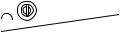
 Hardware Overview
Camera unit
SDHC card slot
Status indicator LED 


Power button
Control button
Dome cover
Dome bracket |
Dome bracket |
|
Dome ring |
Dome ring |
screw (4) |
Dome cover |
screw (4) |

AXIS Q6032/Q6034/Q6035 Installation Guide |
Page 7 |
Hard ceiling mount
 Mounting plate
Drop ceiling mount
Mounting plate screw (3)
Bracket arm (3)
Bracket arm screw (3) and washer (3)
Bracket ring


 Trim ring
Safety wire
Unit holder (3)
Camera base lid
Camera base lid screw (3)
Hook for safety wire
Part number (P/N) & Serial number (S/N). The serial number may be required during the installation.
Cable tracks
Network connector
Foam gasket
Multi-connector
Top cover
 Top cover screw (4)
ENGLISH

Page 8 |
AXIS Q6032/Q6034/Q6035 Installation Guide |
 Install the hardware
The network camera can be mounted with the cables routed through or along the wall or ceiling.
!IMPORTANT! - To use the network camera outdoors, it must be installed in an approved outdoor housing. Please see www.axis.com for more information on outdoor products.
Prepare for installation
Read all the instructions before preparing to install the network camera since several installation preparation steps require removing the dome ring and the dome cover and would benefit from being completed together.
•The network camera is supplied with a clear transparent cover and a smoked transparent cover. If required, follow the instructions Replace the clear/smoked dome cover (optional), below to replace the dome cover.
•A standard or high capacity SD card (not included) is required to store images locally in the network camera. Follow the instructions Install an SD card (optional), below to remove the dome cover and install an SD card.
Replace the clear/smoked dome cover (optional)
1.Loosen the 4 dome ring screws and remove the dome ring and the dome cover, see illustration on page 6.
2.Remove the 4 dome bracket screws and remove the dome bracket and the dome cover from the dome ring.
3.Attach the dome bracket and the dome cover to the dome ring and tighten the 4 screws.
4.If installing an SD card, refer to the instructions Install an SD card (optional), below.
5.Put the dome ring with the dome cover back in the original position and tighten the screws.
Note:
Be careful not to scratch or damage the dome cover. If possible, keep the protective plastic on the dome cover until the installation is complete.
Install an SD card (optional)
1.Loosen the 4 dome ring screws and remove the dome ring and the dome cover, see illustration on page 6.
2.Insert an SD card (not included) into the SDHC (Secure Digital High Capacity) card slot.
3.Put the dome ring with the dome cover back in the original position and tighten the screws.
Notes:
The SD card is automatically mounted when inserted into the SDHC card slot. However, before removing the SD card it should be unmounted through the camera’s web pages. Go to Setup > System Options > Storage > SD Card and click Unmount. For more information, please see the User Manual available from the AXIS Network Video Product CD supplied with this product or from the website at www.axis.com

AXIS Q6032/Q6034/Q6035 Installation Guide |
Page 9 |
Hard ceiling mount
1.Prepare the ceiling for installation of the mounting plate, use the supplied drill template to position the holes. Make sure to use drill bits, screws and plugs that are appropriate for the material.
2.Install the mounting plate. The arrow on the mounting plate will align with the logotype on the camera.
Mounting plate
ENGLISH
 Safety wire
3.Loosen the 3 camera base lid screws and remove the camera base lid, see illustration on page 7.
4.Secure the camera using the supplied safety wire.
5.Route and connect the network cable and the multi-connector cable, if applicable, to the network camera. Be careful not to damage the cables when connecting them. Make sure the foam gasket holes are aligned with the cable tracks and, if applicable, remove the cut-out piece for the multi-connector cable from the foam gasket.
6.Put the camera base lid back in its original position and fasten the screws.
7.Slide the unit holders on the network camera into the slots on the mounting plate and rotate the camera unit.
8.Install the High PoE Midspan 1-Port, see Install AXIS T8123 High PoE Midspan 1-port, on page 13.
9.Check that the indicator LEDs on the midspan indicate the correct conditions, see the table on page 24 for further details.
Page 10 |
AXIS Q6032/Q6034/Q6035 Installation Guide |
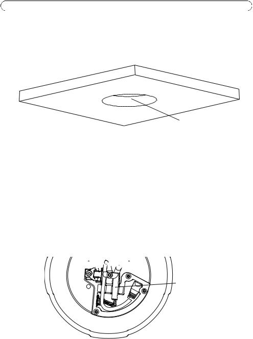
Drop ceiling mount
1.Remove the ceiling tile in which the drop ceiling mount is to be fitted.
2.Use the supplied template to mark the position for the 225 mm (8.9 in.) hole in the ceiling tile. Cut around the template.
Ceiling tile
Hole diameter 225 mm (8.9 in.)
Notes:
•The combined weight of the camera and ceiling mount is approximately 3.2 kg (7.1 lb.). Check that the ceiling material is strong enough to support this weight.
•The ceiling tile should be 5 mm–60 mm (0.2 in.–2.4 in.) thick.
3.Put the ceiling bracket into the ceiling tile, see illustration on page 11. Make sure the arrows on the mounting plate and the ceiling bracket are pointing in the same direction for the logotypes on the camera and the trim ring to align.
4.Tighten the bracket arm screws using a Torx 20 screwdriver head.
5.Loosen the 3 camera base lid screws and remove the camera base lid, see illustration on page 7.
6.Route and connect the network cable and the multi-connector cable, if applicable, to the network camera. Be careful not to damage the cables when connecting them. Make sure the foam gasket holes are aligned with the cable tracks and, if applicable, remove the cut-out piece for the multi-connector cable from the foam gasket. Turn the cable holders to keep the cables in place, see illustration below.


 Cable holders
Multi-connector cable
 Network cable
7. Put the camera base lid back in its original position and fasten the screws.
AXIS Q6032/Q6034/Q6035 Installation Guide |
Page 11 |
8. Secure the camera using the supplied safety wire.
Ceiling bracket |
Safety wire |
Hook for |
|
safety wire |
|
|
|
Ceiling tile 
ENGLISH
9.Slide the unit holders on the network camera into the slots on the mounting plate and rotate the camera unit.
10.Install the High PoE Midspan 1-Port, see Install AXIS T8123 High PoE Midspan 1-port, on page 13.
11.Check that the indicator LEDs on the midspan indicate the correct conditions. See the table on page 24 for further details.
12.Install the ceiling tile, with the camera mounted, into the ceiling.
13.Place the trim ring over the ceiling bracket and tighten the screws.
Trim ring
Trim ring screws

Page 12 |
AXIS Q6032/Q6034/Q6035 Installation Guide |
Bracket mount (optional accessory)
1.Install the selected bracket according to the instructions supplied with the bracket. If drilling is required, make sure to use drill bits, screws and plugs that are appropriate for the material.
2.Loosen the 3 camera base lid screws and remove the camera base lid, see illustration on page 7.
3.Route the network cable and the multi-connector cable, if applicable, through the holes in the mounting bracket.
4.Hook the camera to the safety wire on the bracket.
Torx T30
Screws
Safety |
|
Slots for |
wire |
|
unit holders |
|
Wall bracket (mounting example)
5.Connect the network cable and, if applicable, the multi-connector cable to the network camera.
6.Install AXIS T8123, see Install AXIS T8123 High PoE Midspan 1-port, on page 13.
7.Put the camera base lid back in its original position.
8.Slide the unit holders on the network camera into the slots on the bracket and rotate the camera unit.
9.Secure the network camera to the mounting bracket by fastening the 3 screws (Torx T30).

AXIS Q6032/Q6034/Q6035 Installation Guide |
Page 13 |
Install AXIS T8123 High PoE Midspan 1-port
AXIS T8123 High PoE Midspan 1-port enables Axis network video products with high power consumption to receive data and power over the same Ethernet cable. Follow these instructions to connect AXIS T8123.
1.Connect AXIS T8123 (Data in) to the network switch using a standard network cable.
2.Connect AXIS T8123 (Data and Power Out) to the network camera, using the network cable that has been connected to the camera.
3.Connect AXIS T8123 to an AC outlet (100–240 V AC), using the supplied power cable.
AXIS T8123 |
|
Data & |
|
Port |
Power out Data in |
|
|
connectivity indicator
AC Input connectivity indicator
Network camera |
Ethernet |
For information on the LEDs on the midspan, see Status indicators, on page 24.
ENGLISH

Page 14 |
AXIS Q6032/Q6034/Q6035 Installation Guide |
 Assign an IP Address
Most networks today have a DHCP server that automatically assigns IP addresses to connected devices. If your network does not have a DHCP server the network camera will use 192.168.0.90 as the default IP address.
If you would like to assign a static IP address, the recommended method in Windows is either AXIS IP Utility or AXIS Camera Management. Depending on the number of cameras you wish to install, use the method that best suits your purpose.
Both of these free applications are available on the AXIS Network Video Product CD supplied with this product, or they can be downloaded from www.axis.com
Method |
Recommended for |
Operating system |
|
|
|
AXIS IP Utility |
Single camera |
Windows |
See page 15 |
Small installations |
|
|
|
|
AXIS Camera Management |
Multiple cameras |
Windows 2000 |
See page 16 |
Large installations |
Windows XP Pro |
|
Installation on a different subnet |
Windows 2003 Server |
|
|
Windows Vista |
|
|
Windows 7 |
|
|
|
Notes:
•If assigning the IP address fails, check that there is no firewall blocking the operation.
•For other methods of assigning or discovering the IP address, e.g. in other operating systems, see page 20.

AXIS Q6032/Q6034/Q6035 Installation Guide |
Page 15 |
AXIS IP Utility - single camera/small installation
AXIS IP Utility automatically discovers and displays Axis devices on your network. The application can also be used to manually assign a static IP address.
ENGLISH
Note that the computer running AXIS IP Utility must be on the same network segment (physical subnet) as the network camera.
Automatic discovery
1.Check that the network camera is connected to the network and that power has been applied.
2.Start AXIS IP Utility.
3.When the camera appears in the window, double-click it to open its home page.
4.See page 17 for instructions on how to assign the password.
Assign the IP address manually (optional)
1.Acquire an unused IP address on the same network segment as your computer.
2.Select the network camera in the list.
3. Click the Assign new IP address to the selected device button  and enter the IP address.
4.Click Assign and follow the on-screen instructions. Note that the camera must be restarted within 2 minutes for the new IP address to be set.
5.Click Home Page to access the camera’s web pages.
6.See page 17 for instructions on how to set the password.
Page 16 |
AXIS Q6032/Q6034/Q6035 Installation Guide |
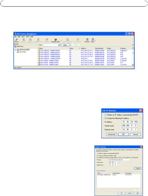
AXIS Camera Management - multiple cameras/large installations
AXIS Camera Management can automatically discover multiple Axis devices, show connection status, manage firmware upgrades and set IP addresses.
Automatic discovery
1.Check that the camera is connected to the network and that power has been applied.
2.Start AXIS Camera Management. When the network camera appears in the window, right-click the link and select Live View Home Page.
3.See page 17 for instructions on how to set the password.
Assign an IP address in a single device
1.Select the network camera in AXIS Camera Management and click the Assign IP button. 
2.Select Assign the following IP address and enter the IP address, subnet mask and default router the device will use.
3.Click OK.
Assign IP addresses in multiple devices
AXIS Camera Management speeds up the process of assigning IP addresses to multiple devices, by suggesting IP addresses from a specified range.
1.Select the devices you wish to configure (different models can be selected) and click the Assign IP button. 
2.Select Assign the following IP address range and enter the range of IP addresses, the subnet mask and default router the devices will use.
3.Click Update. Suggested IP addresses are listed under New IP Addresses and can be edited by selecting a device and clicking Edit.
4.Click OK.

AXIS Q6032/Q6034/Q6035 Installation Guide |
Page 17 |
 Set the Password
To gain access to the product, the password for the default administrator user root must be set. This is done in the ‘Configure Root Password’ dialog, which is displayed when the network camera is accessed for the first time.
To prevent network eavesdropping when setting the root password, this can be done via an encrypted HTTPS connection, which requires an HTTPS certificate.
Note: HTTPS (Hypertext Transfer Protocol over SSL) is a protocol used to encrypt the traffic between web browsers and servers. The HTTPS certificate controls the encrypted exchange of information.
To set the password via a standard HTTP connection, enter it directly in the first dialog shown below.
To set the password via an encrypted HTTPS connection, follow these steps:
1.Click the Create self-signed certificate button.
2.Provide the requested information and click OK. The certificate is created and the password can now be set securely. All traffic to and from the network camera is encrypted from this point on.
3.Enter a password and then re-enter it to confirm the spelling. Click OK. The password has now been configured.
To create an HTTPS connection, start by clicking this button.
To configure the password directly via an unencrypted connection, enter the password here.
ENGLISH

Page 18 |
AXIS Q6032/Q6034/Q6035 Installation Guide |
4.To log in, enter the user name “root” in the dialog as requested.
Note: The default administrator user name root cannot be deleted.
5.Enter the password as set above, and click OK.
Note: If the password is lost, the camera must be reset to the factory default settings. See page 25.
6.AXIS Q6035: The capture mode must be set the first time the camera is accessed. Select the desired Capture Mode from the dropdown list and click OK.
Note: The capture mode can be changed later from the product’s web pages, but this will reset most other settings. For more information, see the online help or the User Manual.

AXIS Q6032/Q6034/Q6035 Installation Guide |
Page 19 |
Access the video stream
The Live View page of the network camera is displayed, with links to the Setup tools, which allow you to customize the camera.
If required, click Yes to install AMC (AXIS Media Control), which allows viewing of the video stream in Internet Explorer. You will need administrator rights on the computer to do this.
If required, click the link to install missing decoders.
Note: To install AMC in Windows Vista, you must run Internet Explorer as an administrator. Right-click the Internet Explorer icon and select Run as administrator.
Setup - Provides all the tools for configuring the camera to requirements.
Help - Displays online help on all aspects of using the camera.
ENGLISH

Page 20 |
AXIS Q6032/Q6034/Q6035 Installation Guide |
Other Methods of Setting the IP address
The table below shows the other methods available for setting or discovering the IP address. All methods are enabled by default, and all can be disabled.
|
Use in operating |
Notes |
|
system |
|
|
|
|
UPnP™ |
Windows |
When enabled on your computer, the camera is automatically detected |
|
|
and added to “My Network Places.” |
|
|
|
Bonjour |
MAC OSX |
Applicable to browsers with support for Bonjour. Navigate to the |
|
(10.4 or later) |
Bojour bookmark in your browser (e.g. Safari) and click on the link to |
|
|
access the camera’s web pages. |
|
|
|
AXIS Dynamic |
All |
A free service from Axis that allows you to quickly and simply install |
DNS Service |
|
your camera. Requires an Internet connection with no HTTP proxy. See |
|
|
www.axiscam.net for more information |
|
|
|
ARP/Ping |
All |
See below. The command must be issued within 2 minutes of |
|
|
connecting power to the camera. |
|
|
|
DHCP server |
All |
To view the admin pages for the network DHCP server, see the server’s |
|
|
own documentation. |
|
|
|
AXIS Video Hosting System (AVHS)
The camera can also be connected to an AVHS service for hosted video. If you have subscribed to an AVHS service, follow the instructions in the Service Provider’s Installation Guide. For more information and help to find a local AVHS Service Provider, go to www.axis.com/hosting
A Camera owner authentication key is supplied with this product. The key is associated with the camera’s unique serial number (S/N) as shown on the top of the label.
Note:
Save the key for future reference.
AXIS Q6032/Q6034/Q6035 Installation Guide |
Page 21 |
Set the IP address with ARP/Ping
1.Acquire an IP address on the same network segment your computer is connected to.
2.Locate the serial number (S/N) on the product label on the camera.
3.Open a command prompt on your computer and enter the following commands:
Windows syntax: |
Windows example: |
|
|
|
|
|
|
arp -s <IP Address> <Serial Number> |
arp -s 192.168.0.125 00-40-8c-18-10-00 |
|
|
ping -l 408 -t <IP Address> |
ping -l 408 -t 192.168.0.125 |
|
|
|
|
|
|
UNIX/Linux/Mac syntax: |
UNIX/Linux/Mac example: |
|
|
|
ENGLISH |
||
|
|
|
|
arp -s <IP Address> <Serial Number> temp |
arp -s 192.168.0.125 00:40:8c:18:10:00 temp |
|
|
|
|
||
ping -s 408 <IP Address> |
ping -s 408 192.168.0.125 |
|
|
|
|
|
|
|
|
|
|
4.Check that the network cable is connected to the camera and then start/restart the camera, by disconnecting and reconnecting power.
5.Close the command prompt when you see ‘Reply from 192.168.0.125: ...’ or similar.
6.In your browser, type in http://<IP address> in the Location/Address field and press Enter on your keyboard.
Notes:
•To open a command prompt in Windows: from the Start menu, select Run... and type cmd. Click OK.
•To use the ARP command in WIndows Vista, right-click the command prompt icon and select Run as administrator.
•To use the ARP command on a Mac OS X, use the Terminal utility in Application > Utilities.

Page 22 |
AXIS Q6032/Q6034/Q6035 Installation Guide |
Unit Connectors
Network connector – RJ-45 Ethernet connector. Supports Power over Ethernet Plus (PoE+), see table below. Use AXIS T8123 High PoE Midspan 1-port (included).
Product |
Maximum power consumption PoE (IEEE802.3at) |
|
|
AXIS Q6032 |
21 W |
|
|
AXIS Q6034 |
21 W |
|
|
AXIS Q6035 |
23 W |
|
|
Note:
Always use a shielded network cable (STP) between the camera and the end point and ensure that the end point is properly grounded. Installations of Axis cameras using a shielded network cable (STP) and a properly grounded end point have been tested to comply with industry immunity standards’ levels such as surge protection. Any other installation method will void the warranty and leave the unit at a risk.
Multi-connector – Terminal connector for connection of external equipment:
•Audio equipment
•Input/output (I/O) devices
•AC/DC power supply
When connecting external equipment to the network camera, a multi-connector cable is required in order to maintain the IP52 rating. The multi-connector cable can be purchased from your Axis reseller. For more information, please see the User Manual available from the AXIS Network Video Product CD supplied with this product or from the website at www.axis.com
SDHC card slot – A standard or high capacity SD card (not included) is required to store images locally in the network camera. To insert and remove the SD card, the dome ring and the dome cover must be removed, see Install an SD card (optional), on page 8.
Note:
Before removal, the SD card should be unmounted to prevent corruption of recordings. To unmount the SD card, go to Setup > System Options > Storage > SD Card and click
Unmount. For more information, please see the User Manual available from the AXIS Network Video Product CD supplied with this product or from the website at www.axis.com

AXIS Q6032/Q6034/Q6035 Installation Guide |
Page 23 |
Multi-connector cable (not included)
When connecting external equipment to the camera, a multi-connector cable is required in order to maintain the camera’s IP52 rating. The multi-connector cable can be purchased from your Axis reseller.
Connect the multi-connector cable to the camera’s multi connector, see illustration on page 7 and instructions on page 9 and page 10. The cable provides the following connectors:
Power connector – 3-pin terminal block used for power input.
ENGLISH
DC power input |
AC power input |
|
|
|
|
Product |
Power consumption DC |
Power consumption AC |
|
|
|
AXIS Q6032 |
24-34 V DC, max. 19 W |
20-24 V AC, max. 27 VA |
|
|
|
AXIS Q6034 |
24-34 V DC, max. 19 W |
20-24 V AC, max. 27 VA |
|
|
|
AXIS Q6035 |
24-34 V DC, max. 20 W |
20-24 V AC, max. 30 VA |
|
|
|
Audio in (pink) – 3.5 mm input for a mono microphone, or a line-in mono signal (left channel is used from a stereo signal).
Audio out (green) – 3.5 mm output for audio (line level) that can be connected to a public address (PA) system or an active speaker with a built-in amplifier. A pair of headphones can also be attached. A stereo connector must be used for the audio out.
I/O terminal connector – Used in applications for e.g. motion detection, event triggering, time lapse recording and alarm notifications. In addition to an auxiliary power and a GND pin, the I/O terminal connector has 4 pins that can be configured as either input or output. These pins provide the interface to:
•Digital output - For connecting external devices such as relays and LEDs. Connected devices can be activated by the VAPIX® Application Programming Interface, output buttons on the Live View page or by an Event Type. The output will show as active (shown under
Events > Port Status if the alarm device is activated.

Page 24 |
AXIS Q6032/Q6034/Q6035 Installation Guide |
•Digital input - An alarm input for connecting devices that can toggle between an open and closed circuit, for example: PIRs, door/window contacts, glass break detectors, etc. When a signal is received the state changes an the input becomes active (shown under
Events > Port Status).
Function |
Pin |
Notes |
Specifications |
|
|
|
|
GND |
1 |
Ground |
|
|
|
|
|
3.3 V DC |
2 |
Can be used to power auxiliary equipment. |
Max. load = 250 mA |
Power |
|
Note: This pin can only be used as power out. |
|
|
|
|
|
Configurable |
3-6 |
Digital input – Connect to GND to activate, or leave floating |
Min. input = -40 V DC |
(input or |
|
(unconnected) to deactivate. |
Max. input = +40 V DC |
Output) |
|
|
|
|
Digital output – Uses an open-drain NFET transistor with the |
Max. load = 100 mA |
|
|
|
||
|
|
source connected to GND. If used with an external relay, a |
Max. voltage = +40 V DC |
|
|
diode must be connected in parallel with the load, for pro- |
|
|
|
tection against voltage transients. |
|
|
|
|
|
Status indicators
Product |
Color |
Indication |
|
|
|
|
|
AXIS Q6032 |
Unlit |
Steady connection/normal operation |
|
AXIS Q6034 |
|
|
|
Amber |
Steady during system initiating and reset to factory |
||
AXIS Q6035 |
|||
|
default. Flashes during firmware upgrade. |
||
|
|
||
|
|
|
|
|
Amber/red |
No network connection |
|
|
|
|
|
|
Red |
Firmware upgrade failure |
|
|
|
|
|
|
Green |
Steady for 10 sec. after successful restart |
|
|
|
|
Product |
LED |
Color |
Indication |
|
|
|
|
AXIS T8123 |
Port |
Unlit |
No camera connected |
|
|
|
|
|
|
Flashing |
Power overload or other input voltage error |
|
|
|
|
|
|
Green |
Camera connected, normal behavior |
|
|
|
|
|
AC input |
Steady green |
AC power connected |
|
|
|
|

AXIS Q6032/Q6034/Q6035 Installation Guide |
Page 25 |
Resetting to the Factory Default Settings
To reset the camera to the original factory default settings, use the control button and the power button on the side of the camera, see Hardware Overview, on page 6, as described below:
Using the control and power buttons will reset all the parameters, including the IP address, to the factory default settings:
1. |
Remove the dome ring and the dome cover, this will automatically disconnect power from the |
|
|
|
camera, see Replace the clear/smoked dome cover (optional), on page 8. |
|
|
2. |
Press and hold the control button and the power button at the same time. |
|
|
ENGLISH |
|||
3. |
Continue to hold down the control and power buttons until the status indicator color changes |
||
|
|||
|
to amber (this may take up to 15 seconds). |
|
|
4. |
Release the control button. |
|
|
5. |
When the status indicator changes to green (which may take up to 1 minute), the process is |
|
|
|
complete and the camera has been reset. The unit now has the default IP address 192.168.0.90 |
|
|
6. |
Release the power button and put the dome ring and dome cover back in their original position. |
|
|
7. |
Re-assign the IP address, using one of the methods described in Assign an IP Address, on page |
|
|
|
14. |
|
It is also possible to reset parameters to the original factory default settings via the web interface. For more information, please see the online help or the User Manual available from the AXIS Network Video Product CD supplied with this product.
Accessing the Camera from the Internet
Once installed, your network camera is accessible on your local network (LAN). To access the camera from the Internet, network routers must be configured to allow incoming traffic, which is usually done on a specific port.
•HTTP port (default port 80) for viewing and configuration
•RTSP port (default port 554) for viewing H.264 video streams
Please refer to the documentation for your router for further instructions. For more information on this and other topics, visit the Axis Support Web at www.axis.com/techsup
Further Information
The User Manual is available from the Axis Web site at www.axis.com or from the AXIS Network Video Product CD supplied with this product.
Tip!
Visit www.axis.com/techsup to check if there is updated firmware available for your network camera. To see the currently installed firmware version, see Setup > About.
Mesures de sécurité
Lisez attentivement ce guide d’installation avant d’installer le produit. Conservez le guide d’installation pour une utilisation ultérieure.
 ATTENTION!
•Pour éviter d’endommager le produit Axis, utilisez l’emballage d’origine ou un emballage équivalent pour le transporter.
•Conservez le produit Axis dans un environnement sec et aéré.
•Évitez d’exposer le produit Axis à des vibrations, des chocs ou une trop forte pression et ne l’installez pas sur des supports instables, ou encore sur des surfaces ou des murs instables ou vibrants; cela risquerait de l’endommager.
•Utilisez uniquement des outils à main pour l’installation du produit Axis: l’utilisation d’outils électriques ou l’usage excessif de la force risquent de l’endommager.
•N’utilisez ni produits chimiques, ni substances caustiques, ni nettoyeurs aérosol. Utilisez un chiffon humide pour le nettoyage.
•N’utilisez que des accessoires conformes aux caractéristiques techniques du produit. Ceux-ci peuvent être fournis par Axis ou un fournisseur tiers.
•Utilisez uniquement des pièces de rechange fournies ou recommandées par Axis.
•Ne tentez pas de réparer le produit vous-même, contactez Axis ou votre revendeur Axis pour tout problème de maintenance.
 IMPORTANT!
•Ce produit Axis doit être utilisé conformément aux lois et réglementations locales en vigueur.
•Pour pouvoir être utilisé à l’extérieur, ce produit Axis doit être placé dans un boîtier d’extérieur homologué.
Remplacement des piles
Ce produit Axis nécessite une pile au lithium CR2032 de 3V pour l’alimentation de son horloge en temps réel interne. Dans des conditions normales d’utilisation, cette pile est censée durer au moins 5ans. Si la pile est faible, le fonctionnement de l’horloge en temps réel peut être affecté et entraîner sa réinitialisation à chaque mise sous tension. Un message enregistré apparaît lorsque la pile doit être remplacée. Ne remplacez la pile que lorsque cela est nécessaire.
Si la pile doit être remplacée, veuillez contacter www.axis.com/techsup pour obtenir de l’aide.
•Le remplacement incorrect de la pile peut entraîner un risque d’explosion.
•Remplacez la pile par une pile identique ou équivalente uniquement, en respectant les recommandations du fabricant.
•Jetez les piles usagées conformément aux consignes du fabricant.
Nettoyage de la bulle du dôme
•Veillez à ne pas rayer ou endommager la bulle du dôme. Ne nettoyez pas la bulle du dôme si elle semble propre à l’œil nu et ne frottez jamais sa surface. Un nettoyage excessif peut l’endommager.
•Pour le nettoyage général de la bulle du dôme, il est recommandé d’utiliser un savon ou un détergent neutre sans solvant, non abrasif, avec de l’eau et un chiffon doux. Rincez abondamment avec de l’eau douce et tiède. Séchez à l’aide d’un chiffon doux pour éviter les salissures d’eau.
•N’utilisez jamais de détergents forts, d’essence, de benzène ou d’acétone, etc. et évitez toute exposition directe aux rayons du soleil ou à des températures élevées lors du nettoyage.

AXIS Q6032/Q6034/Q6035 Guide d'installation Page 27
AXIS Q6032/Q6034/Q6035
Guide d’installation
Ce guide d’installation explique comment installer la AXIS Q6032/Q6034/Q6035 PTZ Dome Network Camera sur votre réseau. Pour toute autre question concernant l’utilisation du produit, reportezvous au manuel de l’utilisateur du produit, que vous trouverez sur le CD joint ou sur le site www.axis.com
Procédure d’installation
1. Vérifiez le contenu de l’emballage par rapport à la liste ci-dessous. |
|
|||
2. Vue d’ensemble du matériel. Reportez-vous à la page 28. |
|
|||
3. Installation du matériel. |
|
|||
FRAN |
||||
• Préparation de l’installation, reportez-vous à la page 30. |
||||
|
||||
• Fixation au plafond, reportez-vous à la page 31. |
AISÇ |
|||
• Fixation au faux plafond, reportez-vous à la page 32. |
||||
• Fixation du support (accessoire en option), reportez-vous à la page 34. |
|
|||
• Installation de l’injecteur High PoE AXIS T8123 à 1 port, reportez-vous à la page 35. |
|
|||
4. Attribution d’une adresse IP. Reportez-vous à la page 36. |
|
|||
5. Configuration du mot de passe. Reportez-vous à page 39. |
|
|||
Contenu de l’emballage |
|
|||
|
|
|
|
|
Élément |
Modèles/variantes/remarques |
|
|
|
|
|
|
|
|
Caméra réseau |
AXIS Q6032/Q6034/Q6035 |
|
|
|
|
|
|
|
|
Bulle du dôme |
Bulle transparente non fumée (prémontée) |
|
|
|
|
Bulle transparente fumée |
|
|
|
|
|
|
|
|
Kit de montage |
Kit de fixation au plafond et au faux plafond |
|
|
|
|
|
|
|
|
Injecteur High PoE |
AXIS T8123 |
|
|
|
|
|
|
|
|
CD |
CD du produit de vidéo sur IP AXIS comprenant la documentation, les outils |
|
|
|
|
d’installation et les autres logiciels |
|
|
|
|
|
|
|
|
Documentation imprimée |
AXIS Q6032/Q6034/Q6035 Guide d’installation de la Network Camera (le |
|
|
|
|
présent document) |
|
|
|
|
Document de garantie d’Axis |
|
|
|
|
Gabarit de perçage |
|
|
|
|
Étiquettes de numéro de série supplémentaires (2x) |
|
|
|
|
Clé d’authentification AVHS |
|
|
|
|
|
|
|
|
|
|
|
|
|
Accessoires en option |
Accessoires de montage AXIS T91A |
|
|
|
|
Câble multiconnexion pour la connexion d’E/S, audio et de l´alimentation |
|
|
|
|
Consultez le site à l’adresse www.axis.com pour plus d’informations sur les |
|
|
|
|
accessoires disponibles |
|
|
|
|
|
|
|
|

Page 28 |
AXIS Q6032/Q6034/Q6035 Guide d'installation |
 Présentation du matériel
Caméra
Logement de carte SDHC
Voyant d’état 


Bouton marche/arrêt
Bouton de commande
Bulle du dôme
Vis du support |
Support du dôme |
Vis de l’anneau |
Anneau du dôme |
du dôme (4) |
Bulle du dôme du dôme (4) |

AXIS Q6032/Q6034/Q6035 Guide d'installation |
Page 29 |
Fixation au plafond
 Plaque de fixation
Fixation au faux plafond
Vis de fixation de la plaque (3)
Bras de support (3)
Vis du bras
de support (3) et rondelle (3)
Anneau de support


 Rondelle décorative
Fil de sécurité
Support de rack (3)
Couvercle de base de la caméra
Vis du couvercle de base de la caméra (3)
Crochet pour fil de sécurité
Référence et numéro de série.
 Le numéro de série peut être demandé pendant l’installation.
Passages pour câble
Connecteur réseau
Joint en mousse
Multiconnecteur
Couvercle supérieur
 Vis du couvercle supérieur (4)
AISÇFRAN

Page 30 |
AXIS Q6032/Q6034/Q6035 Guide d'installation |
 Installation du matériel
La caméra réseau peut être montée avec les câbles d’alimentation acheminés à travers le mur ou le plafond ou le long de l’un d’eux.
!IMPORTANT ! - Pour pouvoir utiliser la caméra réseau à l’extérieur, elle doit être placée dans un caisson extérieur homologué. Visitez le site www.axis.com pour plus d’informations sur le caisson extérieur.
Préparation de l’installation
Lisez toutes les instructions avant de préparer l’installation de la caméra réseau. En effet, de nombreuses étapes de cette préparation requièrent le retrait de l’anneau et de la bulle du dôme et il serait plus judicieux de les effectuer ensemble.
•La caméra réseau est fournie avec deux bulles transparentes (non fumée et fumée). Si nécessaire, suivez les instructions décrites dans la Replacement de la bulle du dôme fumé/ non fumé (facultatif) ci-après pour remplacer la bulle du dôme.
•Une carte SD standard ou haute capacité (non fournie) est requise pour stocker des images en local sur la caméra réseau. Suivez les instructions décrites dans la section Installation d’une carte SD (facultatif) ci-après pour retirer la bulle du dôme et installer la carte SD.
Replacement de la bulle du dôme fumé/non fumé (facultatif)
1.Desserrez les quatre vis de l’anneau du dôme puis retirez ce dernier ainsi que la bulle du dôme, voir l’illustrationn à la page 28.
2.Retirez les quatre vis du support du dôme puis enlevez ce dernier ainsi que la bulle du dôme de l’anneau du dôme.
3.Fixez le support et la bulle du dôme à l’anneau du dôme puis serrez les quatre vis.
4.En cas d’installation de la carte SD, reportez-vous aux instructions décrites dans la section
Installation d’une carte SD (facultatif) ci-après.
5.Remettez en place l’anneau et la bulle du dôme, puis serrez les vis.
Remarque :
Veillez à ne pas rayer ou endommager la bulle du dôme. Laissez, si possible, la protection en plastique sur la bulle du dôme jusqu’à la fin de l’installation.
Installation d’une carte SD (facultatif)
1.Desserrez les quatre vis de l’anneau du dôme puis retirez ce dernier et la bulle du dôme, voir l’illustration à la page 28.
2.Insérez une carte SD (non fournie) dans le logement de carte SDHC (Secure Digital High Capacity).
Loading...