


 Loading...
INSTALLATION GUIDE
AXIS T95A00 Dome Housing
AXIS T95A10 Dome Housing
ESPAÑOL ITALIANO DEUTSCH FRANÇAIS ENGLISH

AXIS T95A00/T95A10 Dome Housing |
Page 3 |
AXIS T95A00/T95A10 Dome Housing
The AXIS T95A00/T95A10 Dome Housing can be used in both indoor and outdoor camera installations. Follow these instructions to complete the installation of the AXIS T95A00/T95A10 Dome Housing and Axis network camera.
Warning! High voltage - the electrical connection must be made by an authorized electrician. Please observe relevant national and local regulations for the installation.
•“Package Contents” on page 4
•“Installation” on page 5
•“Technical Specifications” on page 16
Safety Rules
Only qualified technical personnel may install this device.
•Disconnect power before any technical work on the appliance.
•Do not use old or worn out power cables.
•Never make changes or connections that are not shown in this handbook; improper use of the appliance may cause serious hazard and may damage the product.
•Use original spare parts. Non-original spare parts could cause fire, electrical discharge, or other hazards.
•Before installing the device, check the supplied material to make sure it corresponds with the order specification.
•Please retain this document for future reference.
Axis Network Cameras
The AXIS T95A00/T95A10 Dome Housing supports the following camera models:
Camera Model:
•AXIS 213 PTZ
•AXIS 214 PTZ
•AXIS 215 PTZ
•AXIS 231D+/232D+
•AXIS 233D
Note:
Before you begin, make sure that the AXIS T95A00/T95A10 Dome Housing package contents, and the required cables, tools, and documentation are available. See “Package Contents” on page 4.
ENGLISH

Page 4 |
AXIS T95A00/T95A10 Dome Housing |
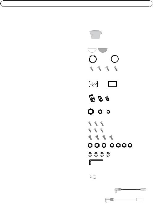
Package Contents
Large box:
(1) AXIS T95A00/T95A10 Dome Housing
Small box:
(2) Domes - transparent and smoked
(1) Fastening ring for dome
(1) Rubber gasket for dome
(4) M3x10mm screws for fastening ring
Plastic bag:
(1) Plate for cable glands
(1) Gasket for the cable gland plate
(1) M20 cable gland
(1) M16 cable gland
(1) M12 cable gland
(1) Plastic nut for M20 cable gland
(1) Plastic nut for M16 cable gland
(1) Plastic nut for M12 cable gland
(3) M3x10mm screws
(3) M3x8mm screws
(4) M4x10mm screws
(3)M3 nuts
(4)M4 nuts
(4) Lock washers
(1) 3mm Allen key
Plastic bag:
(1) Desiccant salt bag
Additional parts:
(1) Power cable for AXIS 213 PTZ, AXIS 214 PTZ, and AXIS 215 PTZ
(1) Ethernet cable with 90 degree angle for AXIS 231D+/232D+

AXIS T95A00/T95A10 Dome Housing |
Page 5 |
Tools/ Parts not included
Phillips screw driver
Ceiling bracket for AXIS 231D+/232D+ (supplied with the network camera)
Adjustable wrench
Other required parts
Mounting bracket |
See www.axis.com for available brackets and accessories |
Power cable |
Examples: |
|
AWG20, 100-240 VAC cable (AXIS T95A00 Dome Housing) |
|
AWG22, 24 VAC cable (AXIS T95A10 Dome Housing) |
Network cable |
CAT 5 shielded twisted pair (STP) cable recommended |
Soft cloth |
Recommended for protecting the dome while installing the housing |
Note:
Not all screws provided are required for all camera installations.
Installation
Follow these steps indoors before the installation outdoor to save time at the installation site.
Top cover |
Black |
cable |
Blue cable |
|
|
||
|
|
|
Universal Adaptor |
Attach Universal Adaptor to camera
1.Remove the top cover of the housing (with four screws) from the housing using the 3mm allen key.
2.For AXIS T95A00 Dome Housing only - remove the two connectors (with black and blue cables) attached to the circuit board on top of the Universal Adapter.
3.Loosen the three screws holding the Universal Adaptor. Rotate slightly and remove the Universal Adaptor from the housing.
4.Attach the Universal Adaptor to the camera. For details see page 14.
ENGLISH
Note:
Do not install the camera in the housing at this point. Transport it carefully to the place of installation first.

Page 6 |
AXIS T95A00/T95A10 Dome Housing |
Fix the dome cover to the housing
Place the fastening ring over the dome. Insert the four 10mm M3 screws, so you hold the ring, the dome cover, and the gasket together. Fix the dome cover (transparent or smoked) at the bottom of the housing.
Fastening ring
Dome Rubber gasket
Housing
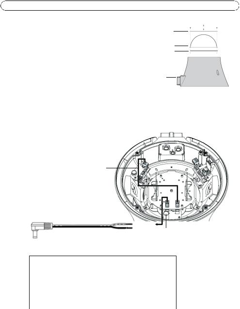
AXIS 213 PTZ, AXIS 214 PTZ, and AXIS 215 PTZ power connection
Connect the (provided) power cable to the 12 VDC output as shown in the picture.
brown cable
Network camera power cable
12V DC
power connector
AXIS T95A00/T95A10 Dome Housing output 12V DC
Camera power cable |
Housing power connector |
|
|
black |
GND |
red |
12 V |
|
|

AXIS T95A00/T95A10 Dome Housing |
Page 7 |
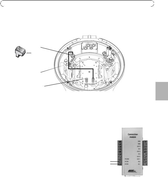
AXIS 231D+/232D+ and AXIS 233D power connection
1.Unplug the connector from the 12 VDC power supply opposite the bracket opening as shown in the illustration below.
|
|
|
|
|
|
|
|
|
|
|
24V |
|
|
|
|
|
|
|
|
~ |
|
|
|
|
|
|
|
||
|
|
~+ |
|
|
|
|
|
|
|
- |
|
|
|
|
|
|
|
||
|
|
|
|
|
|
|
|
|
|
|
Brown cable |
|
|
|
|
|
|
||
|
|
|
|
|
|
|
|
|
remove green |
|
|
|
|
|
|
|
|
|
|
|
|
12 VDC |
|
|
|
|
|
connector |
|
|
|
|
|
|
|
|
block |
||
|
|
|
|
|
|
||||
|
|
power connector |
|
|
|
|
|
|
|
|
|
|
|
|
|
|
|
|
|
2.Remove the 2-pin green connector block from the cables.
3.Connect the cable to the camera’s power connector as described below:
AXIS 231D+/232D+
•AXIS T95A00 Dome Housing (24V DC)
•AXIS T95A10 Dome Housing (24V AC)
Connect the brown cable to the 24V AC/DC pins on the AXIS 231D+/232D+ connection module (see illustration).
Note:
The AXIS 231D+/232D+ connection module contains a rectifier so the cables can be connected either way.
AXIS 231D+/232D+ Connection module
24V AC/DC
ENGLISH

Page 8 |
AXIS T95A00/T95A10 Dome Housing |
AXIS 233D
As the camera is not yet installed in the housing, this is a preparatory step showing how to connect the brown cables from the 24V connector to the 8-pin green connector block (supplied with the camera). When the camera is later installed in the housing, this connector block will then be connected to the camera itself. Referring to the connection diagram on the right, connect the brown cables for your version of the T95A.
•AXIS T95A00 Dome Housing (24V DC)
Connect +24V to AC/DC+
Connect -24V to GND/DC-
•AXIS T95A10 Dome Housing (24V AC)
Connect +24V to AC/DC+
Connect -24V to AC.
Prepare the cable gland plate
AXIS 233D
Connector
AC AC/DC+ GND/DC-
12V out
GND Line out GND
Line/Mic in
Fix the 3 cable glands to the cable gland plate and place the cable gland plugs on them. Insert the four M3 screws through the gasket and plate.
The preparation for the network camera installation is now complete.

AXIS T95A00/T95A10 Dome Housing |
Page 9 |
Install the mounting bracket
Note:
Make sure all cables are in place but not powered, before you install the bracket. Keep cables unpowered until the installation is complete.
1.Install the bracket for the AXIS T95A00/T95A10 Dome Housing on a wall and make sure that the screws and plugs are appropriate for the wall (wood, metal, concrete, or any other), and suitable for the weight of the housing. To install the bracket in the correct direction, see figure below.
230 |
140 |
|
110 |
14 |
77 |
31 |
|
70 |
|
182 |
150 |
ENGLISH
81 |
14 |
|
9 |
2.Pull a sufficient length of the cables through the bracket for the housing and camera (approximately 50 cm).
Note:
Visit the Axis web site at www.axis.com for a comprehensive list of the available brackets and accessories.

Page 10 |
AXIS T95A00/T95A10 Dome Housing |
Mount the housing to the bracket
Notes:
•Ensure that the bracket is securely fastened, and cables are pulled through it before mounting the camera housing. Ensure that no power is connected to the cables.
•It is recommended that you place a soft, clean cloth (not included) into the dome to ensure it remains clean until the time when you need to mount the camera.
1.If the top cover of the housing was attached to facilitate transportation, detach it again at this point.
2.Position the AXIS T95A00/T95A10 Dome Housing against the bracket, making sure to pull the cables (power, Ethernet, and I/O cables if applicable) into the housing, and tighten the two 25mm M5 allen key screws (included with the bracket).
3.Pull the cables through the cable glands, and secure the hole in the bracket with the cable gland plate. Ensure the cables are securely fastened in the cable glands.
4.Remove the protective cloth (if you have used one) from the dome, and remove traces of dust.
Install the camera in the housing
1.Make sure power is disconnected from the housing before installing the camera.
2.Connect the network cable to the Ethernet port in the camera.
3.Connect the power cable to the camera.
4.If applicable, connect the I/O cables to the connectors as described in the installation guide supplied with the camera.
5.Lower the Universal Adaptor with the attached camera into the AXIS T95A00/T95A10 Dome Housing and tighten the 3 screws.
6.Connect power to the housing as described below.
•“For AXIS T95A00 Dome Housing” on page 11
•“For AXIS T95A10 Dome Housing” on page 12

AXIS T95A00/T95A10 Dome Housing |
Page 11 |
For AXIS T95A00 Dome Housing
Attach the power cable (100-240V AC) to the housing.
100-240V AC
L 
N 
GND 
100-240V AC input
ENGLISH
Overview of complete installation
Blue
Black
Out 230V AC (not required for camera
installation)
Out 24V DC
Brown cable
Out 12V DC |
In 100-240V AC |
|
Earth the housing applying the two supplied cables to the cover and body using the M3 screws and toothed washers.

Page 12 |
AXIS T95A00/T95A10 Dome Housing |
For AXIS T95A10 Dome Housing
Attach the power cable (24V AC) to the housing.
L 24V AC


N 24V AC
GND
Overview of complete installation
Red
24V AC In
24V AC Out
Brown
12V DC Out
The safety wire should remain fastened during service.
Place the desiccant bag on the side of the housing
away from cables and electrical components.
Desiccant bag
Note:
For AXIS 231D+/232D+: Place the connection module in a suitable position on
top of the bracket, away from cables and electrical components.

AXIS T95A00/T95A10 Dome Housing |
Page 13 |
Complete the installation
1.Check that all cables and wires in the housing are properly connected.
2.Replace the top cover of the housing and tighten the screws using the supplied Allen key.
3.Connect the AXIS T95A housing to the power supply (110-240VAC or 24VAC - depending on the version you are using).
4.Follow the instructions in the Installation Guide to install the camera on the network.
The installation is now complete.
The Axis network camera installation guide is shipped with the camera or available from the Axis website at www.axis.com.
To remove the sunshield
Remove the three screws on the side of the sunshield with a Phillips screw driver; remove the screw on the top center of the cover plate with the 4 mm Allen key.
It is recommended that this is done after the installation.
ENGLISH
Page 14 |
AXIS T95A00/T95A10 Dome Housing |
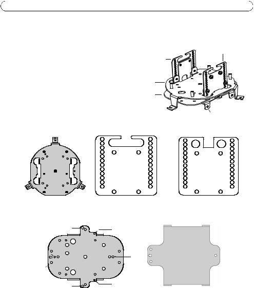
Mount the Universal Adaptor to the camera |
|
The Universal Adaptor consists of five plates. |
Universal adaptor when assembled |
|
|
|
Spacer plate |
|
Spacer plate |
|
Fixed plate |
|
Moving plate |
|
AXIS 233D plate |
|
|
A |
|
|
A |
|
|
B |
|
|
B |
|
|
C |
1 |
1 |
C |
|
|
D |
D |
||
PF2 |
|
|
|
||
PF1 |
E |
|
|
E |
|
|
|
|
|||
|
PF1 |
F |
|
|
F |
PF3 |
PF3 |
|
|
||
|
|
G |
|
|
G |
|
PF2 |
H |
|
|
H |
|
|
I |
|
|
I |
PF3 |
PF3 |
L |
|
|
L |
M |
|
|
M |
||
|
PF1 |
|
|
||
PF2 |
PF1 |
N |
|
|
N |
|
|
|
|
||
|
|
2 |
2 |
|
|
|
|
|
|
Fixed plate (view from below) |
Spacer plate |
|||
|
|
|||
|
|
PM9-PM11 |
PM2-PM5 |
|
|
|
|
|
|
|
|
PM3 |
|
|
|
PM6 |
PM4 |
PM4 |
|
|
PM8 |
|
||
PM1-PM10 |
|
|
|
|
|
PM7 |
PM7 |
|
|
PM2-PM5 |
|
PM7 |
PM10 |
|
|
|
|
PM1-PM3 |
|
|
|
PM3 |
PM6 |
|
|
|
|
||
|
|
PM7-PM8 |
|
|
PM1-PM10 |
|
|
PM10 |
|
|
PM7 |
PM7 |
|
|
|
|
|
||
|
PM6 |
PM8 |
PM4 |
|
|
|
|
||
|
|
PM4 |
|
|
|
|
|
|
|
|
|
PM3 |
PM2-PM5 |
|
|
|
PM9-PM11 |
|
|
A |
A |
BB
CC
1 1 DD
E |
E |
F |
F |
G |
G |
H |
H |
I |
I |
L |
L |
M |
M |
N |
N |
2 |
2 |
Spacer plate
|
|
|
AXIS 233D plate |
|
Moving plate |
||||
|
||||

AXIS T95A00/T95A10 Dome Housing |
Page 15 |
For AXIS 233D
1.Adjust the height of the spacer plates to hole F+1 on the spacer plate (See illustration).
2.Place the camera within the four ears of the Universal Adaptor and screw it onto place. The adaptor is supplied already configured for the AXIS 233D.
For AXIS 213 PTZ
1.Detach the AXIS 233D plate by removing the three nuts.
2.Adjust the height of the spacer plates to holes B+2 on the spacer plate.
3.Place the AXIS 213 PTZ on the Moving plate.
4.Fasten the AXIS 213 PTZ to the two PM 11 holes with two screws.
For AXIS 214 PTZ
1.Detach the AXIS 233D plate by removing the three nuts.
2.Adjust the height of the spacer plates to holes E+1 on the spacer plate.
3.Place the AXIS 214 PTZ on the Moving plate.
4.Fasten the AXIS 214 PTZ to the three PM5 holes with three screws.
For AXIS 215 PTZ
1.Detach the AXIS 233D plate by removing the three nuts.
2.Adjust the height of the spacer plates to holes E+2 on the spacer plate.
3.Place the AXIS 215 PTZ on the Moving plate.
4.Fasten the AXIS 215 PTZ to the four PM 10 holes with four screws and nuts.
For AXIS 231D+/232D+
1.Unscrew the fixed plate from the Universal Adaptor.
2.Attach the ceiling bracket to the PF2 holes on the fixed plate. You may find this easier to do by temporarily removing the PCB from the top of the fixed plate (T95A00 only).
3.Pull the provided 90° angle Ethernet connector and connection module cable through the center of the ceiling bracket (supplied with the camera).
4.Connect the connection module cable and the angled Ethernet connector to the camera.
5.Guide the studs on the base of the camera into the holes on the ceiling bracket and rotate it to fix in position.
ENGLISH

Page 16 |
AXIS T95A00/T95A10 Dome Housing |
Technical Specifications
General |
|
|
|
Built in die-cast aluminium |
RAL9002 color |
Epoxypolyester powder paint |
|
|
|
Lower dome in polycarbonate |
Smoked or transparent |
|
|
Sunshield in ABS for outdoor use |
RAL9002 color |
|
|
Mechanical |
|
|
|
External dimensions with sunshield |
Ø 351 x 335 mm (13.8 x 13.2”) |
|
|
External dimensions without sunshield |
Ø 314 x 322 mm (12.4 x 12.7”) |
|
|
3 cable glands |
1x M20 with Ø cable 3,5 - 7,5 mm (0.1 - 0.3”) |
|
1x M16 with Ø cable 3,5 - 7 mm (0.1 - 0.3”) |
|
1x M12 with Ø cable 5 - 10 mm (0.2 - 0.4”) |
|
|
Other |
Protective gasket |
|
|
Electrical |
|
|
|
Fan assisted heater, operating temperature range: |
• AXIS T95A00 Dome Housing: |
15°C to 22°C (±3°C) |
IN 230 V AC, consumption 44 W max |
59°F to 71°F (±5 °F) |
• AXIS T95A10 Dome Housing: |
|
IN 24 V AC, consumption 24 W max |
|
|
Internal power connectors |
• AXIS T95A00 Dome Housing: |
|
IN 100/240 V AC, 50/60 Hz |
|
OUT 12 V DC, 3 A max |
|
IN 100/240 V AC, 50-60 Hz |
|
OUT 24 V DC, 1.5 A max |
|
• AXIS T95A10 Dome Housing: |
|
IN 24 V AC, 50/60 Hz, OUT 12 V DC, 2 A max |
|
|
Blower in continuous operation. |
|
|
|
Related products |
|
|
|
AXIS T95A61 |
Wall bracket |
|
|
AXIS T95A64 |
Corner adapter |
|
|
AXIS T95A67 |
Pole adapter |
|
|

AXIS T95A00/T95A10 Dome Housing |
Page 17 |
|
|
|
|
|
|
Environment |
|
|
|
|
|
|
|
Indoor / Outdoor |
Operating temperature: -30° C to +50° C (-4° F to |
|
|
|
+122° F) |
|
|
|
|
|
|
Compliance |
|
|
|
|
|
|
|
• CE according to EN61000-6-3, EN 60950, EN50130-4 |
|
|
|
• IP66 according to EN 60529 |
|
|
|
|
|
|
|
Package |
|
|
|
|
|
ENGLISH |
|
|
|
|
|
Unit weight |
AXIS T95A00 Dome Housing / AXIS T95A10 Dome |
|
|
|
|
||
|
Housing - 3.8 kg / 8.3 lb. |
|
|
Package weight |
4.2 kg / 9.3 lb. |
|
|
|
|
|
|
Package dimensions (B x H x L) |
38.5 x 38.5 x 47 cm / 15.1 x 15.1 x 18.5” |
|
|
|
|
|
|

Boîtier de dôme AXIS T95A00/T95A10 |
Page 19 |
Boîtier de dôme AXIS T95A00/T95A10
Le Boîtier de dôme AXIS T95A00/T95A10 peut être utilisé dans les installations de caméra intérieures et extérieures. Procédez comme suit pour installer le Boîtier de dôme AXIS T95A00/T95A10 et la caméra réseau Axis.
Avertissement : Haute tension - le raccordement électrique doit être effectué par un électricien agréé. Veuillez respecter les réglementations nationales et locales concernant l’installation.
•“Contenu de l’emballage” on page 20
•“Installation” on page 21
•“Caractéristiques techniques” on page 32
Règles de sécurité
Seul un personnel technique qualifié est autorisé à installer ce dispositif.
•Débrancher du secteur avant de procéder à tout travail technique sur l’appareil.
•Ne pas utiliser de câbles d’alimentation anciens ou usés.
•Ne jamais effectuer de modifications ou de raccordements ne figurant pas dans ce manuel ; toute utilisation inappropriée de l’appareil peut provoquer des dangers graves et peut endommager le produit.
•Utiliser des pièces détachées d’origine. Les pièces détachées qui ne sont pas d’origine peuvent provoquer des incendies, décharges électriques et autres dangers.
•Avant d’installer le dispositif, vérifiez le matériel fourni pour vous assurer qu’il correspond à la spécification de votre commande.
•Veuillez conserver ce document pour vous y reporter ultérieurement.
Caméras réseau Axis
Le Boîtier de dôme AXIS T95A00/T95A10 est compatible avec les modèles de caméras suivants :
Modèle de caméra :
•AXIS 213 PTZ
•AXIS 214 PTZ
•AXIS 215 PTZ
•AXIS 231D+/232D+
•AXIS 233D
Remarque :
Avant de commencer, passez en revue le contenu de l’emballage Boîtier de dôme AXIS T95A00/T95A10 et vérifiez que les câbles, outils et documentation nécessaires sont disponibles. Cf. “Contenu de l’emballage” on page 20.
FRANÇAIS
Page 20 |
Boîtier de dôme AXIS T95A00/T95A10 |
Contenu de l’emballage
Grande boîte :
(1) Boîtier de dôme AXIS T95A00/T95A10
Petite boîte :
(2) Bulles - transparente et fumée
(1) Anneau de serrage pour la bulle
(1) Joint caoutchouc pour la bulle
(4) Vis M3x10mm pour l’anneau de serrage
Sac en plastique :
(1) Plaque pour les presse-étoupes
(1) Joint pour la plaque de presse-étoupe
(1) Presse-étoupe M20
(1) Presse-étoupe M16
(1) Presse-étoupe M12
(1) Écrou plastique pour le presse-étoupe M20
(1) Écrou plastique pour le presse-étoupe M16
(1) Écrou plastique pour le presse-étoupe M12
(3) Vis M3x10mm
(3) Vis M3x8 mm
(4) Vis M4x10 mm
(3)Écrous M3
(4)Écrous M4
(4) Rondelles frein
(1) Clé hexagonale 3 mm
Sac en plastique :
(1) Sac de dessicateur
Pièces supplémentaires :
(1) Câble d’alimentation pour AXIS 213 PTZ, AXIS 214 PTZ et AXIS 215 PTZ
(1) Câble Ethernet avec angle à 90 degrés pour AXIS 231D+/232D+
Boîtier de dôme AXIS T95A00/T95A10 |
Page 21 |
Outils/Pièces non inclus
Tournevis à pointe cruciforme
Support plafond pour AXIS 231D+/232D+ (fourni avec la caméra réseau)
Clé réglable
Autres pièces nécessaires
Support de fixation |
Voir www.axis.com pour les accessoires et supports disponibles. |
Câble |
Exemples : |
d’alimentation |
Câble AWG20, 100-240 V CA (Boîtier de dôme AXIS T95A00) |
|
Câble AWG22, 24 V CA (Boîtier de dôme AXIS T95A10) |
Câble réseau |
Câble CAT 5 paires torsadées blindé recommandé |
Chiffon doux |
Recommandé pour protéger la bulle lors de l’installation du boîtier |
Remarque :
Toutes les vis fournies ne sont pas nécessaires pour l’installation de toutes les caméras.
Installation
Suivez ces étapes à l’intérieur avant l’installation en extérieur pour gagner du temps sur le site d’installation.
Couvercle supérieur |
Câble Bleu |
Câble noir |
|
|
Adaptateur universel |
Raccorder l’adaptateur universel à la caméra
1.Retirez le couvercle supérieur du boîtier (avec quatre vis) à l’aide de la clé hexagonale de 3 mm fournie.
2.Pour Boîtier de dôme AXIS T95A00 uniquement - retirez les deux connecteurs (avec câbles bleu et noir) fixés au circuit sur le sommet de l’Adaptateur universel.
3.Desserrez les trois vis de l’Adapateur universel. Faites pivoter doucement et retirez l’Adapateur universel du boîtier.
4.Raccordez l’Adaptateur universel à la caméra. Pour plus de détails, reportez-vous à la page 30.
FRANÇAIS
Remarque :
N’installez pas la caméra dans le boîtier pour l’instant. Transportez-la avec précaution jusqu’au lieu d’installation.
Page 22 |
Boîtier de dôme AXIS T95A00/T95A10 |
Fixer la bulle sur le boîtier
Placez l’anneau de serrage sur la bulle. Insérez les quatre vis 10 mm M3 en tenant l’anneau, la bulle et le joint. Fixer la bulle (transparente ou fumée) sur le fond du boîtier.
Anneau de serrage
Dôme Joint caoutchouc
Boîtier
AXIS 213 PTZ, AXIS 214 PTZ, et AXIS 215 PTZ le raccordement électrique
Raccordez le câble électrique (fourni) à la sortie 12 VCC tel qu’indiqué sur l’image.
câble marron
Câble électrique de la caméra réseau
12 V CC
connecteur d’alimentation
Boîtier de dôme AXIS T95A00/T95A10 sortie 12 VCC
Câble électrique de la caméra |
Connecteur d’alimentation |
|
électrique du boîtier |
|
|
noir |
GND |
rouge |
12 V |
|
|
Boîtier de dôme AXIS T95A00/T95A10 |
Page 23 |
AXIS 231D+/232D+ et AXIS 233D raccordement électrique
1.Débranchez le connecteur de l’alimentation 12 VCC sur le côté opposé de l’ouverture du support, tel qu’indiqué sur l’illustration ci-dessous.
|
|
|
|
|
|
|
|
|
|
|
|
|
|
|
24 V |
|
|
|
|
|
|
|
|
|
|
~ |
|
|
|
|
|
|
|
||
|
|
|
|
~+ |
|
|
|
|
|
|
|
|
|
- |
|
|
|
|
|
|
|
||
|
|
|
|
|
|
|
|
|
|
|
|
|
|
Câble marron |
|
|
|
|
|
|
|||
|
|
|
|
|
|
|
|
|
|
|
retirer |
|
|
|
|
|
|
|
|
|
|
|
|
|
|
|
|
|
|
|
|
|
|
|
|
12 VCC |
|
|
|
|
|
|
|
|
|
le connecteur vert |
|
le connecteur vert bloqué |
|
|
|
|
|
bloquer |
|||||
|
|
|
|
||||||||
retirer |
|
|
|
|
|
|
|||||
|
|
|
|
|
|
|
|
|
|
|
|
2.Retirez le bloc connecteur vert à 2 broches des câbles.
3.Connectez la caméra au connecteur d’alimentation de la caméra tel que décrit ci-dessous :
AXIS 231D+/232D+
•Boîtier de dôme AXIS T95A00 (24 VCC)
•Boîtier de dôme AXIS T95A10 (24 VCA)
Raccodez le câble marron aux broches 24 V CA/CC sur le AXIS 231D+/232D+ module de raccordement (se reporter à l’illustration).
Remarque :
Le AXIS 231D+/232D+ module de raccordement contient un redresseur afin que les câbles soient raccordés d’un côté ou de l’autre.
AXIS 231D+/232D+ Module de raccordement
24 V CACC
FRANÇAIS

Page 24 |
Boîtier de dôme AXIS T95A00/T95A10 |
AXIS 233D
Puisque la caméra n’est pas encore installée dans le boîtier, il s’agit d’une étape préparatoire indiquant comment raccorder les câbles marron du connecteur 24 V au bloc connecteur vert à 8 broches (fourni avec la caméra). Plus tard, lorsque la caméra est installée dans le boîtier, ce bloc connecteur sera ensuite raccordé à la caméra. En suivant le diagramme de connexion sur la droite, raccordez les câbles marron pour votre version du T95A.
•Boîtier de dôme AXIS T95A00 (24 VCC)
Raccordez +24 V à CA/CC+
Raccordez -24 V à GND/CC-
•Boîtier de dôme AXIS T95A10 (24 VCA)
Raccordez +24 V à CA/CC+
Raccordez -24 V à CA.
Préparez la plaque du presse-étoupe
AXIS 233D
Connecteur
CA CA/CC+ GND/CC- sortie 12V
GND
Sortie de ligne GND Ligne/entrée Mic
Fixez les 3 presse-étoupes à la plaque du presse-étoupe et placez les fiches du presse-étoupe sur ces derniers. Insérez les quatre vis M3 au travers du joint et de la plaque.
La préparation de l’installation de la caméra réseau est achevée.

Boîtier de dôme AXIS T95A00/T95A10 |
Page 25 |
Installation du support de fixation
Remarque :
Assurez-vous que tous les câbles sont installés mais non raccordés au secteur avant d’installer le support. Ne branchez pas les câbles avant la fin de l’installation.
1.Installez le support du Boîtier de dôme AXIS T95A00/T95A10 sur un mur et assurez-vous que les vis et les fiches conviennent au mur (bois, métal, béton ou autre) et sont adaptées au poids du support. Pour installer le support dans la bonne direction, reportez-vous à la figure ci-dessous.
|
230 |
|
140 |
|
|
|
110 |
|
14 |
|
77 |
31 |
|
|
|
70 |
182 |
150 |
FRANÇAIS |
81 |
|
|
14 |
|
|
|
9 |
2.Tirez une longueur suffisante de câbles au travers du support pour le boîtier et la caméra (environ 50 cm).
Remarque :
Visitez le site Web d’Axis à www.axis.com pour obtenir une liste complète des supports et accessoires disponibles.
Loading...