


N73V-S

11
11
1
ASRock N73PV-S / N73V-S Motherboard
EnglishEnglish
EnglishEnglish
English
Copyright Notice:Copyright Notice:
Copyright Notice:Copyright Notice:
Copyright Notice:
No part of this installation guide may be reproduced, transcribed, transmitted, or trans-
lated in any language, in any form or by any means, except duplication of documen-
tation by the purchaser for backup purpose, without written consent of ASRock Inc.
Products and corporate names appearing in this guide may or may not be registered
trademarks or copyrights of their respective companies, and are used only for identifica-
tion or explanation and to the owners’ benefit, without intent to infringe.
Disclaimer:Disclaimer:
Disclaimer:Disclaimer:
Disclaimer:
Specifications and information contained in this guide are furnished for informational
use only and subject to change without notice, and should not be constructed as a
commitment by ASRock. ASRock assumes no responsibility for any errors or omissions
that may appear in this guide.
With respect to the contents of this guide, ASRock does not provide warranty of any kind,
either expressed or implied, including but not limited to the implied warranties or
conditions of merchantability or fitness for a particular purpose. In no event shall
ASRock, its directors, officers, employees, or agents be liable for any indirect, special,
incidental, or consequential damages (including damages for loss of profits, loss of
business, loss of data, interruption of business and the like), even if ASRock has been
advised of the possibility of such damages arising from any defect or error in the guide
or product.
This device complies with Part 15 of the FCC Rules. Operation is subject to the
following two conditions:
(1) this device may not cause harmful interference, and
(2) this device must accept any interference received, including interference that
may cause undesired operation.
CALIFORNIA, USA ONLY
The Lithium battery adopted on this motherboard contains Perchlorate, a toxic
substance controlled in Perchlorate Best Management Practices (BMP) regulations
passed by the California Legislature. When you discard the Lithium battery in
California, USA, please follow the related regulations in advance.
“Perchlorate Material-special handling may apply, see
www.dtsc.ca.gov/hazardouswaste/perchlorate”
ASRock Website: http://www.asrock.com
Published December 2008
Copyright©2008 ASRock INC. All rights reserved.
22
22
2
ASRock N73PV-S / N73V-S Motherboard
EnglishEnglish
EnglishEnglish
English
Motherboard LMotherboard L
Motherboard LMotherboard L
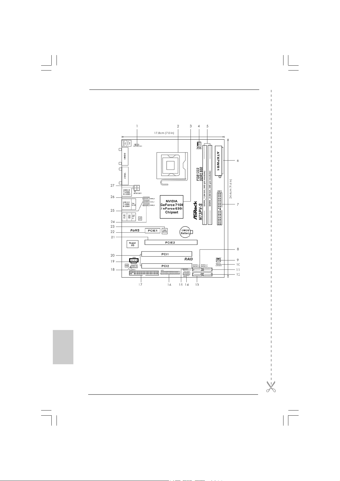
Motherboard L
ayout (N73PVayout (N73PV
ayout (N73PVayout (N73PV
ayout (N73PV
-S)-S)
-S)-S)
-S)
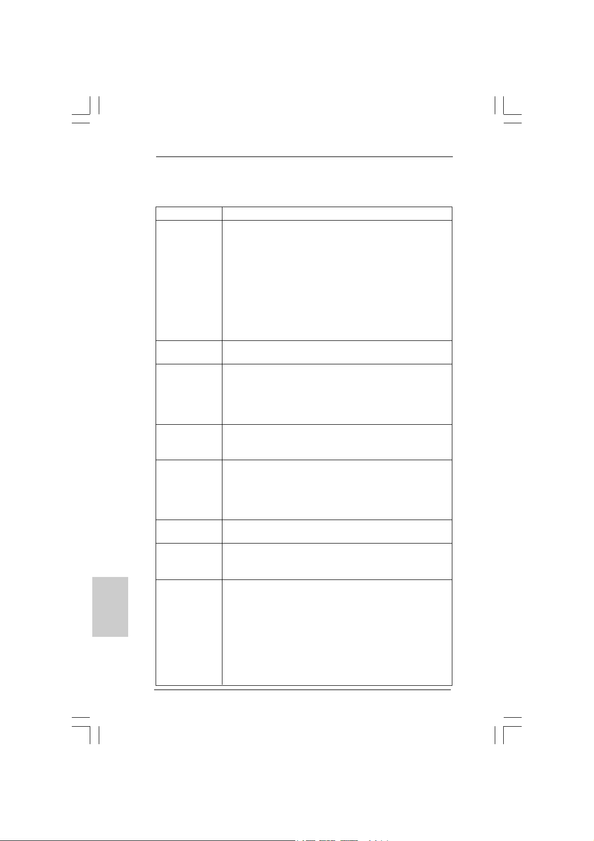
1 PS2_USB_PWR1 Jumper 15 Chassis Speaker Header
2 775-Pin CPU Socket (SPEAKER 1, Purple)
3 NVIDIA GeForce 7100 / nForce 630i Chipset 16 Print Port Header (LPT1, Purple)
4 CPU Fan Connector (CPU_FAN1) 17 Floppy Connector (FLOPPY1)
5 2 x 240-pin DDR2 DIMM Slo ts 18 Front Panel Audio Header
(DDRII_1, DDRII_2; Yellow) (HD_AUDIO1, Lime)
6 ATX Power Connector (ATXPWR1) 19 Internal Audio Connector: CD1 (Black)
7 IDE1 Connector (IDE1, Blue) 20 PCI Slots (PCI1- 2)
8 Primary SATAII Connector (SATAII_1; Red) 21 PCI Express x16 Slot (PCIE2)
9 Chassis Fan Connector (CHA_FAN1) 22 PCI Express x1 Slot (PCIE1)
10 Clear CMOS Jumper (CLRCMOS1) 23 BIOS SPI Chip
11 Third SATAII Connector (SATAII_3; Red) 24 USB 2.0 Header (USB8_9, Blue)
12 Fourth SATAII Connector (SATAII_4; Red) 25 USB 2.0 Header (USB6_7, Blue)
13 Secondary SATAII Connector (SATAII_2; Red) 26 USB 2.0 Header (USB4_5, Blue)
14 System Panel Header (PANEL1, Orange) 27 ATX 12V Connector (ATX12V1)
33
33
3
ASRock N73PV-S / N73V-S Motherboard
EnglishEnglish
EnglishEnglish
English
Motherboard LMotherboard L
Motherboard LMotherboard L
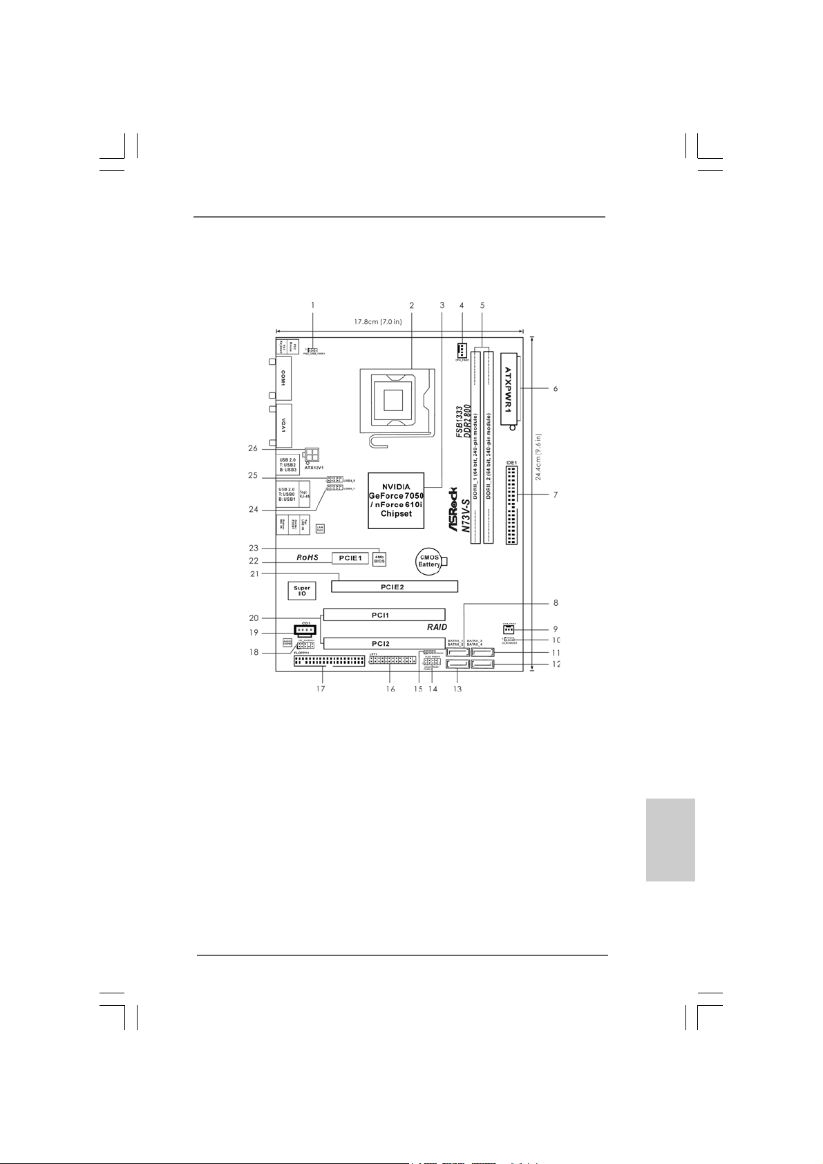
Motherboard L
ayout (N73Vayout (N73V
ayout (N73Vayout (N73V
ayout (N73V
-S)-S)
-S)-S)
-S)
1 PS2_USB_PWR1 Jumper 15 Chassis Speaker Header
2 775-Pin CPU Socket (SPEAKER 1, Purple)
3 NVIDIA GeForce 7050 / nForce 610i Chipset 16 Print Port Header (LPT1, Purple)
4 CPU Fan Connector (CPU_FAN1) 17 Floppy Connector (FLOPPY1)
5 2 x 240-pin DDR2 DIMM Slots 18 Front Panel Audio Header
(DDRII_1, DDRII_2; Yellow) (HD_AUDIO1, Lime)
6 ATX Power Connector (ATXPWR1) 19 Internal Audio Connector: CD1 (Black)
7 IDE1 Connector (IDE1, Blue) 20 PCI Slots (PCI1- 2)
8 Primary SATAII Connector (SATAII_1; Red) 21 PCI Express x16 Slot (PCIE2)
9 Chassis Fan Connector (CHA_FAN1) 22 PCI Express x1 Slot (PCIE1)
10 Clear CMOS Jumper (CLRCMOS1) 23 BIOS SPI Chip
11 Third SATAII Connector (SATAII_3; Red) 24 USB 2.0 Header (USB6_7, Blue)
12 Fourth SATAII Connector (SATAII_4; Red) 25 USB 2.0 Header (USB4_5, Blue)
13 Secondary SATAII Connector (SATAII_2; Red) 26 ATX 12V Connector (ATX12V1)
14 System Panel Header (PANEL1, Orange)
44
44
4
ASRock N73PV-S / N73V-S Motherboard
EnglishEnglish
EnglishEnglish
English
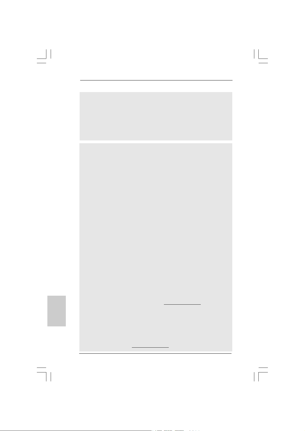
I/O PI/O P
I/O PI/O P
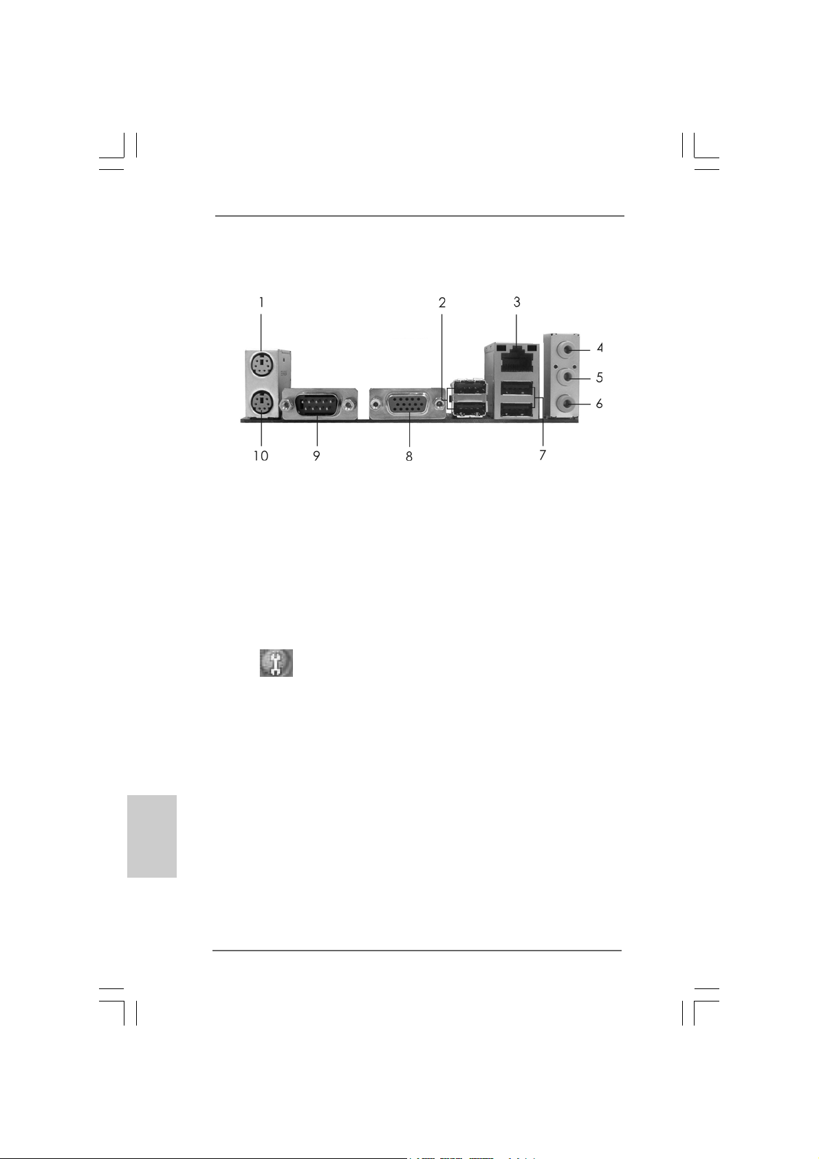
I/O P
anelanel
anelanel
anel
1 PS/2 Mouse Port (Green) 6 Microphone (Pink)
2 USB 2.0 Ports (USB23) 7 USB 2.0 Ports (USB01)
3 RJ-45 Port 8 VGA Port
4 Line In (Light Blue) 9 COM Port
5 Line Out (Lime) 10 PS/2 Keyboard Port (Purple)
* To enable Multi-Streaming function, you need to connect a front panel audio cable to the front
panel audio header. Please refer to below steps for the software setting of Multi-Streaming.
For Windows
®
XP:
After restarting your computer, you will find “Mixer” tool on your system. Please select “Mixer
ToolBox” , click “Enable playback multi-streaming”, and click “ok”. Choose “2CH” or
“4CH” and then you are allowed to select “Realtek HDA Primary output” to use Rear Speaker
and Front Speaker, or select “Realtek HDA Audio 2nd output” to use front panel audio. Then
reboot your system.
For Windows
®
Vista
TM
:
After restarting your computer, please double-click “Realtek HD Audio Manager” on the
system tray. Set “Speaker Configuration” to “Quadraphonic” or “Stereo”. Click “Device
advanced settings”, choose “Make front and rear output devices playbacks two different audio
streams simultaneously”, and click “ok”. Then reboot your system.
55
55
5
ASRock N73PV-S / N73V-S Motherboard
1. Introduction1. Introduction
1. Introduction1. Introduction
1. Introduction
Thank you for purcha sing ASRock N73PV-S / N73V -S motherboard, a reliable motherboard
produced under ASRock’s consistently stringent quality control. It delivers excellent
performance with robust design conforming to ASRock’s commitment to quality and
endurance.
This Quick Installation Guide contains introduction of the motherboard and step-by-
step installation guide. More detailed information of the motherboard can be found in
the user manual presented in the Support CD.
Because the motherboard specifications and the BIOS software might be
updated, the content of this manual will be subject to change without
notice. In case any modifications of this manual occur, the updated
version will be available on ASRock website without further notice. You
may find the latest VGA cards and CPU support lists on ASRock website
as well. ASRock website http://www.asrock.com
If you require technical support related to this motherboard, please visit
our website for specific information about the model you are using.
www.asrock.com/support/index.asp
1.1 P1.1 P
1.1 P1.1 P
1.1 P
ackack
ackack
ack
age Contentsage Contents
age Contentsage Contents
age Contents
ASRock N73PV-S / N73V-S Motherboard
(Micro ATX Form Factor: 9.6-in x 7.0-in, 24.4 cm x 17.8 cm)
ASRock N73PV-S / N73V-S Quick Installation Guide
ASRock N73PV-S / N73V-S Support CD
One 80-conductor Ultra A TA 66/100/133 IDE Ribbon Ca ble (Optional)
One Serial AT A (SAT A) Data Cable (Optional)
One Serial AT A (SA TA) HDD Power Cable (Option al)
One I/O Panel Shield
EnglishEnglish
EnglishEnglish
English
66
66
6
ASRock N73PV-S / N73V-S Motherboard
EnglishEnglish
EnglishEnglish
English
1.21.2
1.21.2
1.2
SpecificationsSpecifications
SpecificationsSpecifications
Specifications
Platform - Micro ATX Form Factor: 9.6-in x 7.0-in, 24.4 cm x 17.8 cm
CPU - LGA 775 for Intel
®
Core
TM
2 Extreme / Core
TM
2 Quad / Core
TM
2 Duo / Pentium
®
Dual Core / Celeron
®
Dual Core / Celeron
®
,
supporting Quad Core Y orkfield a nd Dual Core Wol fdale
processors
- FSB1333/1066/800/533MHz
- Supports Hyper-Threading Technology (see CAUTION 1)
- Supports Untied Overclocking Technology (see CAUTION 2)
- Supports EM64T CPU
Chipset - NVIDIA
®
GeForce 7100 / nForce 630i (N73PV -S)
- NVIDIA
®
GeForce 7050 / nForce 610i (N73V -S)
Memory - 2 x DDR2 DIMM slots
- Support DDR2 800/667/533 non-ECC, un-buf fered memory
- Max. capacity of system memory: 16GB (see CAUTION 3)
Expansion Slot - 1 x PCI Express x16 slot
- 1 x PCI Express x1 slot
- 2 x PCI slots
Graphics - Integrated N VIDIA
®
GeForce 7100 (N73PV -S)
- Integrated N VIDIA
®
GeForce 7050 (N73V -S)
- D X9.0 VGA, Pixel Shader 3.0
- Max. shared memory 256MB (see CAUTION 4)
Audio - 5.1 CH Windows
®
Vista
TM
Premium Level HD Audio
(ALC662 Audio Codec)
LAN - Realtek PHY RTL8201EL
- Speed: 10/100 Ethernet
- Supports Wa ke-On-LAN
Rear Panel I/O I/O Panel
- 1 x PS/2 Mouse Port
- 1 x PS/2 Keyboard Port
- 1 x Serial Port: COM1
- 1 x VGA Port
- 4 x Ready-to-Use USB 2.0 Ports
- 1 x RJ-45 LAN Port with LED (ACT/LINK LED a nd SPEED LED)
- HD Audio Jack: Line in / Front Speaker / Microphone
Connector - 4 x Serial AT AII 3.0Gb/s connectors, support RAID (RAID 0,
RAID 1, RAID 0+1, JBOD and RAID 5), NCQ, AHCI a nd “Hot
Plug” functions (see CAUTION 5)
* RAID 0+1 and RAID 5 functions are for N73PV-S only
- 1 x ATA133 IDE connector (supports 2 x IDE device s)
77
77
7
ASRock N73PV-S / N73V-S Motherboard
EnglishEnglish
EnglishEnglish
English
- 1 x Floppy connector
- 1 x Print port header
- CPU/Chassis FAN connector
- 24 pin A TX power conne ctor
- 4 pin 12V power connector
- CD in header
- Front panel audio connector
- 3 x USB 2.0 headers (support 6 USB 2.0 ports) (N73PV -S)
(see CAUTION 6)
- 2 x USB 2.0 headers (support 4 USB 2.0 ports) (N73V-S)
(see CAUTION 6)
BIOS Feature - 4Mb AMI BIOS
- AMI Legal BIOS
- Supports “Plug and Play”
- ACPI 1.1 Compliance Wake Up Events
- Supports jumperfree
- SMBIOS 2.3.1 Support
- Supports Smart BIOS
Support CD - Drivers, Utilities, AntiV irus Software (T ri al Version)
Unique Feature - ASRock OC Tuner (see CAUTION 7)
- Intelligent Energy Saver (see CAUTION 8)
- Instant Boot
- Hybrid Booster:
- CPU Frequency Stepless Control (see CAUTION 9)
- ASRock U-COP (see CAUTION 10)
- Boot Failure Guard (B.F.G.)
Hardware - CPU T e mperature Sensing
Monitor - Chassis Temperature Sensing
- CPU Fan Ta chometer
- Chassis Fa n Tachometer
- CPU Quiet Fan
- Voltage Monitoring: +12V, +5V, +3.3V, Vcore
OS - Microsoft
®
Windows
®
XP / XP 64-bit / Vista
TM
/ Vista
TM
64-bit compliant
Certifications - FCC, CE
* For detailed product information, please visit our website: http://www.asrock.com
WARNING
Please realize that there is a certain risk involved with overclocking, including
adjusting the setting in the BIOS, applying Untied Overclocking Technology, or using
the third-party overclocking tools. Overclocking may affect your system stability, or
even cause damage to the components and devices of your system. It should be
done at your own risk and expense. We are not responsible for possible damage
caused by overclocking.

88
88
8
ASRock N73PV-S / N73V-S Motherboard
EnglishEnglish
EnglishEnglish
English
CAUTION!
1. About the setting of “Hyper Threading Technology”, please check page
39 of “User Manual“ in the support CD.
2. This motherboard supports Untied Overclocking Technology. Please read
“Untied Overclocking Technology” on page 21 for details.
3. Due to the operating system limitation, the actual memory size may be
less than 4GB for the reservation for system usage under Windows
®
XP
and Windows
®
Vista
TM
. For Windows
®
XP 64-bit and Windows
®
Vista
TM
64-bit with 64-bit CPU, there is no such limitation.
4. The maximum shared memory size is defined by the chipset vendor
and is subject to change. Please check NVIDIA
®
website for the latest
information.
5. Before installing SA TAII hard disk to SATAII connector, ple ase read the “SA TAII
Hard Disk Setup Guide” on page 24 of “User Manual“ in the support CD to
adjust your SATAII hard disk drive to SATAII mode. You can also connect
SATA hard disk to SATAII connector directly.
6. Power Management for USB 2.0 works fine under Microsoft
®
Windows
®
Vista
TM
64-bit / Vista
TM
/ XP 64-bit / XP SP1 or SP2.
7. It is a user-friendly ASRock overclocking tool which allows you to surveil
your system by hardware monitor function and overclock your hardware
devices to get the best system performance under Windows
®
environment. Please visit our website for the operation procedures of
ASRock OC Tuner. ASRock website: http://www.asrock.com
8. Featuring an advanced proprietary hardware and software design,
Intelligent Energy Saver is a revolutionary technology that delivers
unparalleled power savings. In other words, it is able to provide excep-
tional power saving and improve power efficiency without sacrificing
computing performance. Please visit our website for the operation pro-
cedures of Intelligent Energy Saver.
ASRock website: http://www.asrock.com
9. Although this motherboard offers stepless control, it is not recom-
mended to perform over-clocking. Frequencies other than the recom-
mended CPU bus frequencies may cause the instability of the system
or damage the CPU.
10. While CPU overheat is detected, the system will automatically shutdown.
Before you resume the system, please check if the CPU fan on the
motherboard functions properly and unplug the power cord, then plug it
back again. To improve heat dissipation, remember to spray thermal
grease between the CPU and the heatsink when you install the PC
system.
99
99
9
ASRock N73PV-S / N73V-S Motherboard
2.2.
2.2.
2.
InstallationInstallation
InstallationInstallation
Installation
Pre-installation PrecautionsPre-installation Precautions
Pre-installation PrecautionsPre-installation Precautions
Pre-installation Precautions
Take note of the following precautions before you install mother-
board components or change any motherboard settings.
1. Unplug the power cord from the wall socket before touching any
component. Failure to do so may cause severe damage to the
motherboard, peripherals, and/or components.
2. To avoid damaging the motherboard components due to static
electricity, NEVER place your motherboard directly on the carpet
or the like. Also remember to use a grounded wrist strap or touch
a safety grounded object before you handle components.
3. Hold components by the edges and do not touch the ICs.
4. Whenever you uninstall any component, place it on a grounded
antstatic pad or in the bag that comes with the component.
5. When placing screws into the screw holes to secure the
motherboard to the chassis, please do not over-tighten the
screws! Doing so may damage the motherboard.
2.12.1
2.12.1
2.1
CPU InstallationCPU Installation
CPU InstallationCPU Installation
CPU Installation
For the installation of Intel 775-LAND CPU,
please follow the steps below.
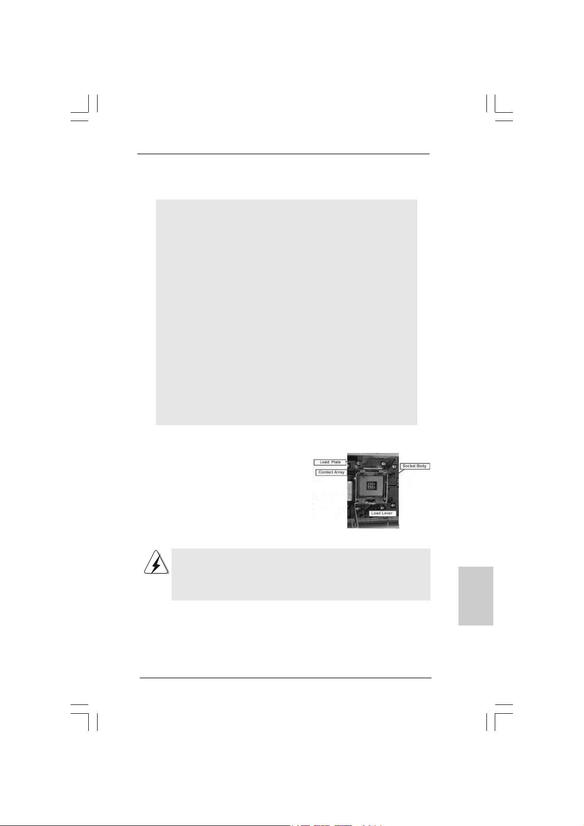
Before you insert the 775-LAND CPU into the socket, please check if
the CPU surface is unclean or if there is any bent pin on the socket.
Do not force to insert the CPU into the socket if above situation is
found. Otherwise, the CPU will be seriously damaged.
775-Pin Socket Overview
EnglishEnglish
EnglishEnglish
English

1010
1010
10
ASRock N73PV-S / N73V-S Motherboard
EnglishEnglish
EnglishEnglish
English
Step 1. Open the socket:
Step 1-1. Disengaging the lever by depressing
down and out on the hook to clear
retention tab.
Step 1-2. Rotate the load lever to fully open po-
sition at approximately 135 degrees.
Step 1-3. Rotate the load plate to fully open po-
sition at approximately 100 degrees.
Step 2. Insert the 775-LAND CPU:
Step 2-1. Hold the CPU by the edges where are
marked with black lines.
Step 2-2. Orient the CPU with IHS (Integrated
Heat Sink) up. Locate Pin1 and the two
orientation key notches.
For proper inserting, please ensure to match the two orientation key
notches of the CPU with the two alignment keys of the socket.
Step 2-3. Carefully pla ce the CPU into the socket
by using a purely vertical motion.
Step 2-4. Verify that the CPU is within the socket
and properly mated to the orient keys.
Step 3. Remove PnP Ca p (Pick a nd Place Cap):
Use your left hand index finger and thumb to
support the load plate edge, engage PnP cap
with right hand thumb and peel the cap from the
socket while pressing on center of PnP cap to
assist in removal.
black line
black line
775-Pin Socket
Pin1
alignment key
alignment key
Pin1
orientation
key notch
orientation
key notch
775-LAND CPU
1111
1111
11
ASRock N73PV-S / N73V-S Motherboard
1. It is recommended to use the cap tab to handle and avoid kicking
off the PnP cap.
2. This cap must be placed if returning the motherboard for after
service.
Step 4. Close the socket:
Step 4-1. Rotate the load plate onto the IHS.
Step 4-2. While pressing down lightly on load
plate, engage the load lever.
Step 4-3. Secure load lever with load plate tab
under retention tab of load lever.
2.22.2
2.22.2
2.2
Installation of CPU Fan and HeatsinkInstallation of CPU Fan and Heatsink
Installation of CPU Fan and HeatsinkInstallation of CPU Fan and Heatsink
Installation of CPU Fan and Heatsink
For proper installation, please kindly refer to the instruction manuals of your CPU fan
and heatsink.
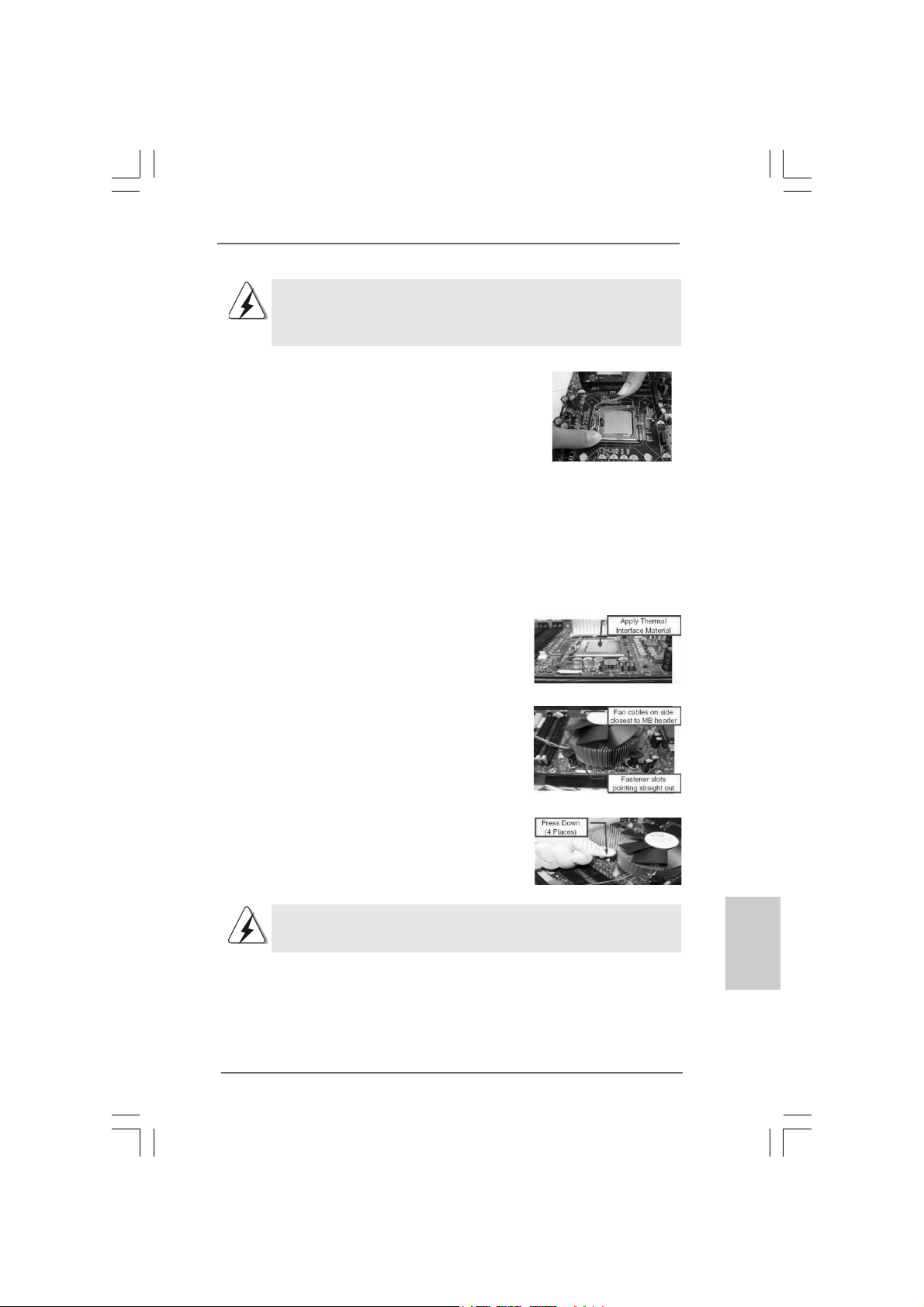
Below is an example to illustrate the installation of the heatsink for 775-LAND CPU.
Step 1. Apply thermal interface material onto center
of IHS on the socket surface.
Step 2. Place the heatsink onto the socket. Ensure
fan cables are oriented on side closest to the
CPU fan connector on the motherboard
(CPU_FAN1, see page 2/3, No. 4).
Step 3. Align fasteners with the motherboard
throughholes.
Step 4. Rotate the fastener clockwise, then press
down on fastener caps with thumb to install
and lock. Repeat with remaining fasteners.
If you press down the fasteners without rotating them clockwise,
the heatsink cannot be secured on the motherboard.
Step 5. Connect fan header with the CPU fan
connector on the motherboard.
Step 6. Secure excess cable with tie-wrap to ensure
cable does not interfere with fan operation or
contact other components.
EnglishEnglish
EnglishEnglish
English

1212
1212
12
ASRock N73PV-S / N73V-S Motherboard
EnglishEnglish
EnglishEnglish
English
2.3 Installation of Memor2.3 Installation of Memor
2.3 Installation of Memor2.3 Installation of Memor
2.3 Installation of Memor
y Modules (DIMM)y Modules (DIMM)
y Modules (DIMM)y Modules (DIMM)
y Modules (DIMM)
This motherboard provides two 240-pin DDR2 (Double Data Rate 2) DIMM slots.
Please make sure to disconnect power supply before adding or
removing DIMMs or the system components.
Step 1. Unlock a DIMM slot by pressing the retaining cli ps outward.
Step 2. Align a DIMM on the slot such that the notch on the DIMM matches the bre a k
on the slot.
The DIMM only fits in one correct orientation. It will cause permanent
damage to the motherboard and the DIMM if you force the DIMM into the
slot at incorrect orientation.
Step 3. Firmly insert the DIMM into the slot until the retaining clips at both ends fully
sna p back in place and the DIMM is properly seated.
1313
1313
13
ASRock N73PV-S / N73V-S Motherboard
2.4 Expansion Slots (PCI and PCI Express Slots)2.4 Expansion Slots (PCI and PCI Express Slots)
2.4 Expansion Slots (PCI and PCI Express Slots)2.4 Expansion Slots (PCI and PCI Express Slots)
2.4 Expansion Slots (PCI and PCI Express Slots)
There are 2 PCI slots and 2 PCI Express slots on this motherboard.
PCI slots: PCI slots are used to install expansion cards that have the 32-bit PCI
interface.
PCIE slots: PCIE1 (PCIE x1 slot) is used for PCI Express cards with x1 lane width
cards, such as Gigabit LAN card, SATA2 card, etc.
PCIE2 (PCIE x16 slot) is used for PCI Express cards with x16 lane
width graphics cards.
Installing an expansion cardInstalling an expansion card
Installing an expansion cardInstalling an expansion card
Installing an expansion card
Step 1. Before installing the expansion card, please make sure that the power supply
is switched off or the power cord is unplugged. Plea se read the documentation
of the expansion card a nd ma ke necessary hardware
settings for the card before you start the installation.
Step 2. Remove the bracket facing the slot that you intend to use. Keep the screws
for later use.
Step 3. Align the card connector with the slot and press firmly until the card is com-
pletely seated on the slot.
Step 4. Fasten the card to the chassis with screws.
EnglishEnglish
EnglishEnglish
English
1414
1414
14
ASRock N73PV-S / N73V-S Motherboard
EnglishEnglish
EnglishEnglish
English
2.5 Easy Multi Monitor Feature2.5 Easy Multi Monitor Feature
2.5 Easy Multi Monitor Feature2.5 Easy Multi Monitor Feature
2.5 Easy Multi Monitor Feature
This motherboard supports Multi Monitor upgrade. With the internal onboard VGA and
the external add-on PCI Express VGA card, you ca n e asily enjoy the benefits of Multi
Monitor feature. Plea se refer to the f ollowing ste ps to set up a multi monitor
environment:
1. Install the NVIDIA
®
PCI Express V GA card to PCIE2 (PCIE x16 slot). Please refer
to page 13 for proper expansion card in stallation procedures for details.
2. Connect the D-Sub monitor ca ble to the VGA/D-Sub port on the I/O panel of this
motherboard. Connect another D-Sub monitor ca ble to the VGA/D-Sub connector of
the add-on PCI Express VGA card. Connect the DVI-D monitor cable to the
V GA/DVI-D conne ctor of the a dd-on PCI Expre ss VGA card.
3. Boot your system. Press <F2> to enter BIOS setup. Enter “Share Memory”
option to adjust the memory capability to [16MB], [32MB], [64MB], [128MB] or
[256MB] to enable the function of onboard VGA/D-sub. Please make sure that
the value you select is less than the total capability of the system memory. If
you do not adjust the BIOS setup, the default value of “Share Memory”, [Auto],
will disable onboard VGA/D-Sub function when the add-on VGA card is inserted
to this motherboard.
4. Install the onboard V GA driver to your system. If you have installed the onboard
V GA driver already, there is no need to install it again.
5. Set up a multi-monitor display.
For Windows
®
XP / XP 64-bit OS:
Right click the desktop, choose “Properties”, and select the “Settings” tab so
that you can adjust the parameters of the multi-monitor according to the steps
below.
A. Click the “Identify” button to display a large number on each monitor.
B. Right-click the display icon in the Display Properties dialog that you wish
to be your primary monitor, and then select “Primary”. When you use
multiple monitors with your card, one monitor will always be Primary, and
all additional monitors will be designated as Secondary.
C. Select the display icon identified by the number 2.
D. Click “Extend my Windows desktop onto this monitor”.
E. Right-click the display icon and select “Attached”, if necessary.
F . Set the “Screen Re solution” a nd “Color Quality” as appropri ate f or the
second monitor. Click “Apply” or “OK” to apply these new values.
G. Repeat steps C through E for the diaplay icon identified by the number
one, two and three.
For Windows
®
Vista
TM
/ Vista
TM
64-bit OS:
Right click the desktop, choose “Personalize”, and sele ct the “Display
Settings” tab so that you can adjust the parameters of the multi-monitor
according to the steps below.
A. Click the number ”2” icon.

1515
1515
15
ASRock N73PV-S / N73V-S Motherboard
B. Click the items “This is my main monitor” and “Extend the desktop onto
this monitor”.
C. Click “OK” to save your change.
D. Repeat steps A through C for the display icon identified by the number
one, two and three.
6. Use Multi Monitor feature. Click and drag the display icons to positions
representing the physical setup of your monitors that you would like to use. The
placement of display icons determines how you move items from one monitor to
another.
2.6 Jumpers Setup2.6 Jumpers Setup
2.6 Jumpers Setup2.6 Jumpers Setup
2.6 Jumpers Setup
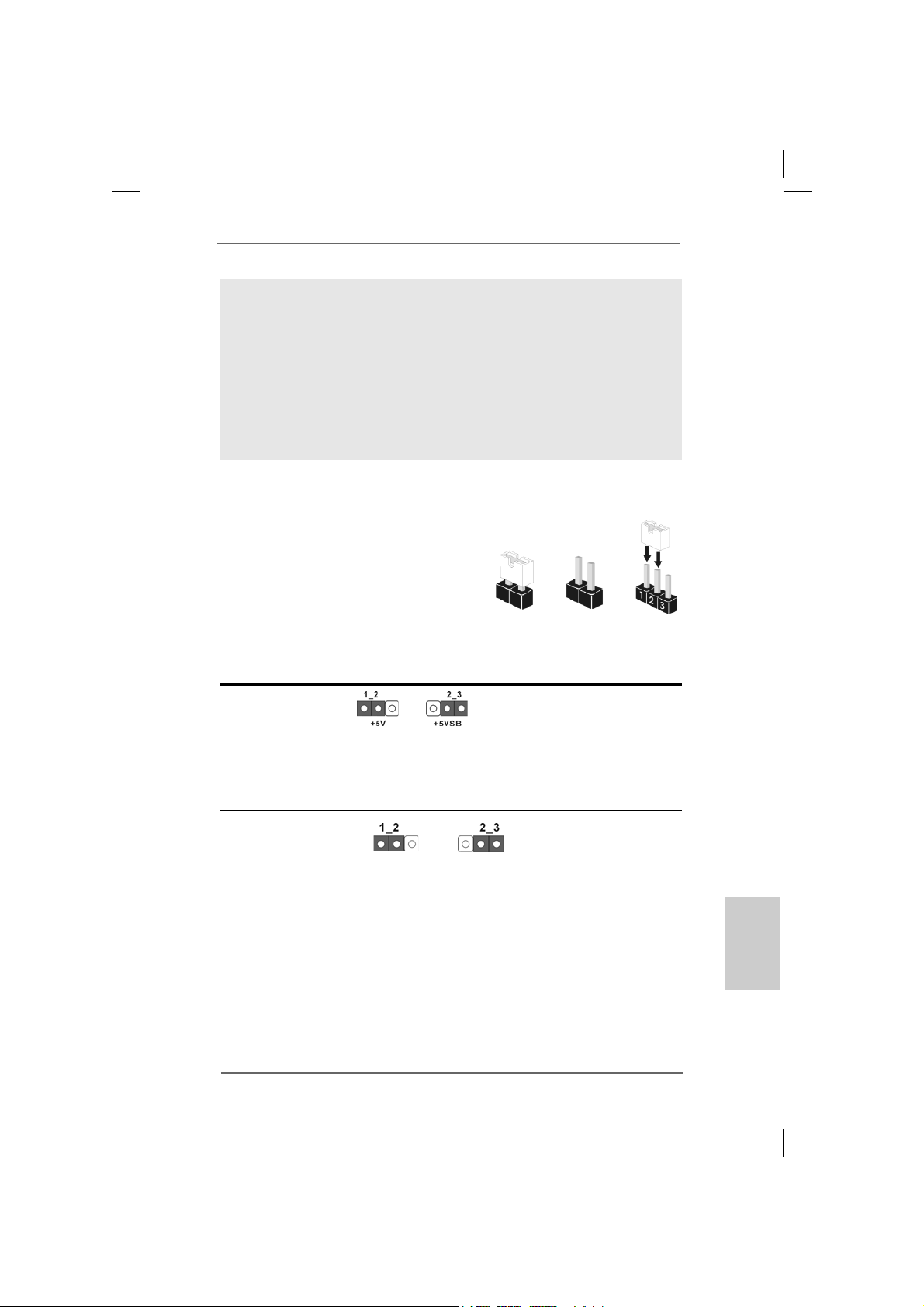
The illustration shows how jumpers are setup.
When the jumper cap is pla ced on
pins, the jumper is “Short”. If no jumper cap is
placed on pins, the jumper is “Open”. The il-
lustration shows a 3-pin jumper whose pin1
an d pin2 are “Short” when jumper cap is placed
on these 2 pins.
Jumper Setting Description
PS2_USB_PWR1 Short pin2, pin3 to enable
(see p.2/3 No. 1) +5VSB (standby) for PS/2
or USB wake up events.
Note: To select +5VSB, it requires 2 Amp and higher sta ndby current provided by power
supply.
Clear CMOS Jumper
(CLRCMOS1)
(see p.2/3 No. 10)
Note: CLRCMOS1 allows you to clear the data in CMOS. The data in CMOS includes
system setup information such as system password, date, time, and system
setup parameters. To clear and reset the system parameters to default setup,
please turn of f the computer and unplug the power cord from the power supply.
After waiting for 15 seconds, use a jumper ca p to short pin2 and pin3 on CLRCMOS1
for 5 seconds. However , please do not clear the CMOS right after you update the
BIOS. If you need to clear the CMOS when you just finish updating the BIOS, you
must boot up the system first, and then shut it down before you do the clear-
CMOS action.
Short Open
Clear CMOSDefault
EnglishEnglish
EnglishEnglish
English
1616
1616
16
ASRock N73PV-S / N73V-S Motherboard
EnglishEnglish
EnglishEnglish
English
2.7 Onboard Headers and Connectors2.7 Onboard Headers and Connectors
2.7 Onboard Headers and Connectors2.7 Onboard Headers and Connectors
2.7 Onboard Headers and Connectors
Onboard headers and connectors are NOT jumpers. Do NOT place
jumper caps over these headers and connectors. Placing jumper
caps over the headers and connectors will cause permanent dam-
age of the motherboard!
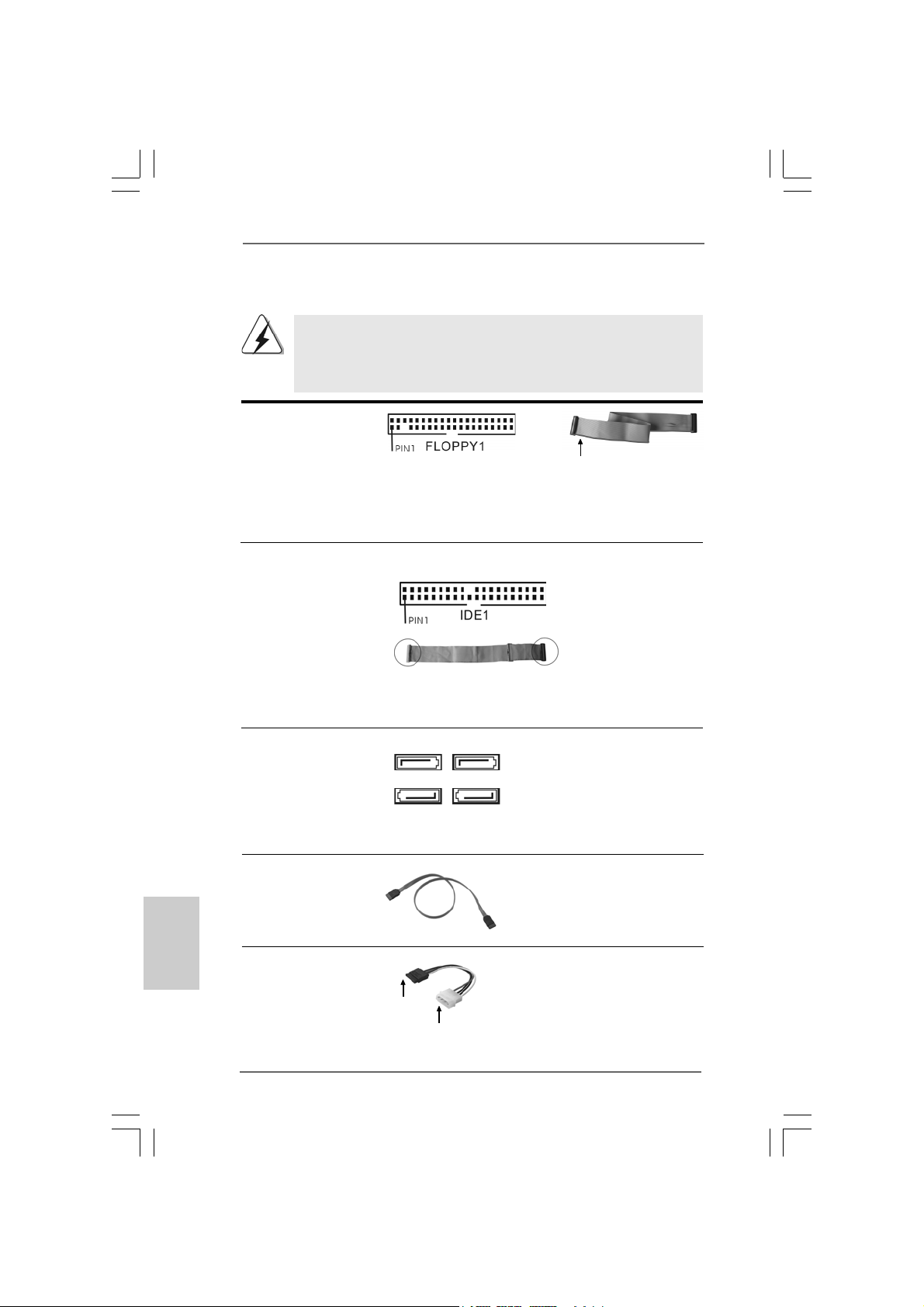
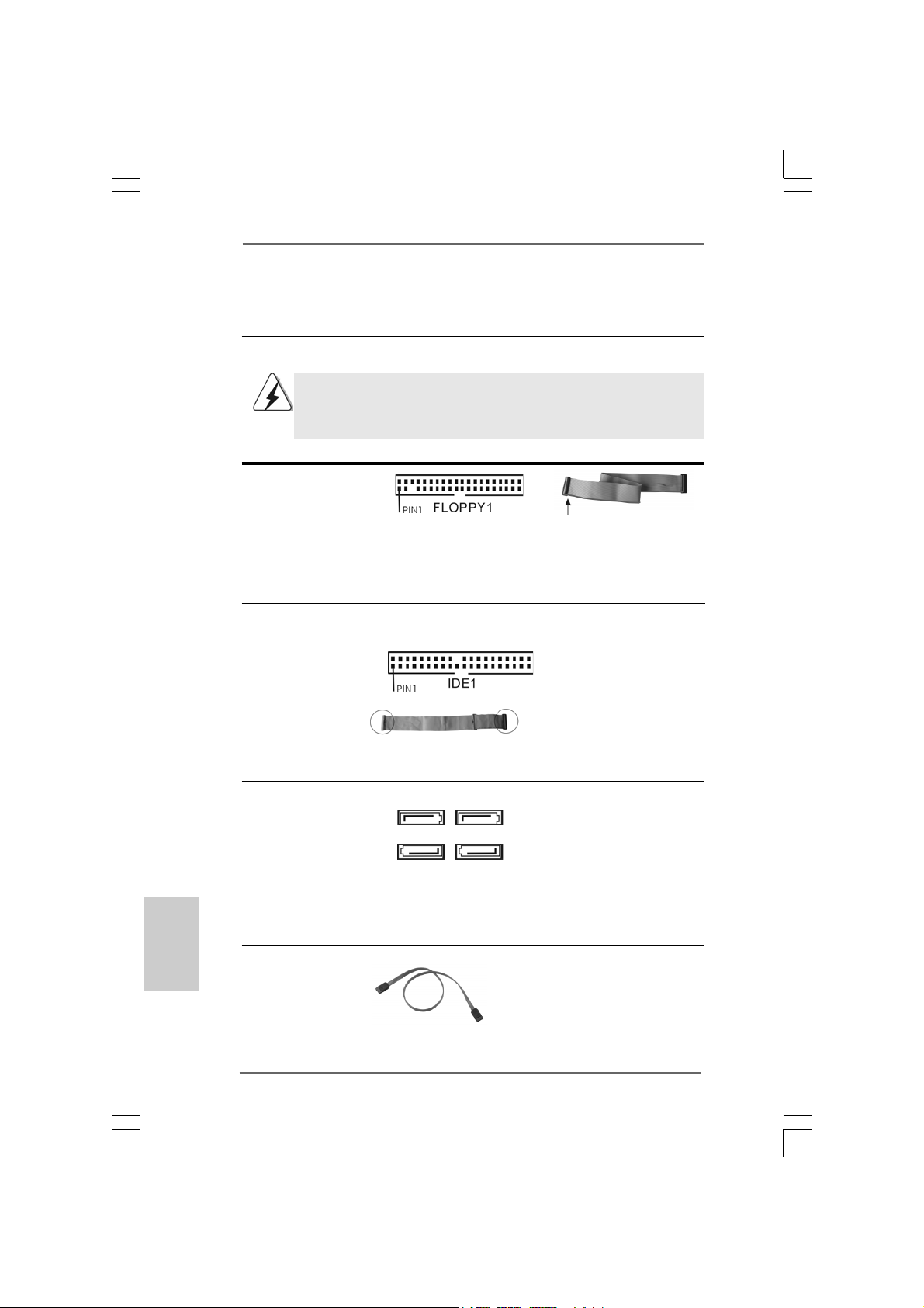
F DD conne ctor
(33-pin FLOPPY1)
(see p.2/3 No. 17)
Note: Ma ke sure the red-striped side of the cable is plugged into Pin1 side of the
connector.
Primary IDE connector (Blue)
(39-pin IDE1, see p.2/3 No. 7)
Note: Please refer to the instruction of your IDE device vendor for the details.
Serial A TAII Connectors These four Serial AT AII (SAT AII)
(SATAII_1: see p.2/3, No. 8) connectors support SATA data
(SATAII_2: see p.2/3, No. 13) cables for internal storage
(SATAII_3: see p.2/3, No. 11) devices. The current SATAII
(SATAII_4: see p.2/3, No. 12) interface allows up to 3.0 Gb/s
data transfer rate.
connect the black end
to the IDE devices
connect the blue end
to the motherboard
80-conductor A T A 66/100133 ca ble
Serial ATA (SATA) Either end of the SATA data ca ble
Data Cable can be connected to the SATA /
(Optional) SATAII hard disk or the SA TAII
connector on this motherboard.
the red-striped side to
Pin1
Serial ATA (SAT A) Plea se connect the black end of
Power Cable SAT A power ca ble to the power
(Optional) connector on each drive. Then
connect the white end of SATA
power cable to the power
connector of the power supply.
connect to
the power
supply
connect to the SATA
HDD power connector
SATAII_1 SATAII_3
SATAII_2 SATAII_4
1717
1717
17
ASRock N73PV-S / N73V-S Motherboard
EnglishEnglish
EnglishEnglish
English
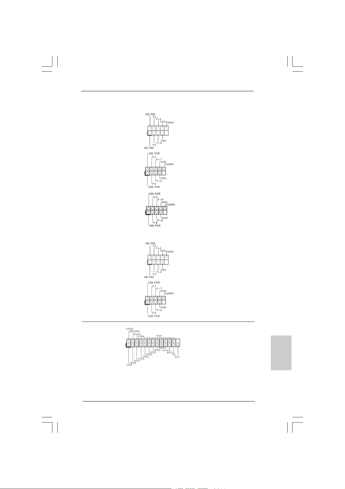
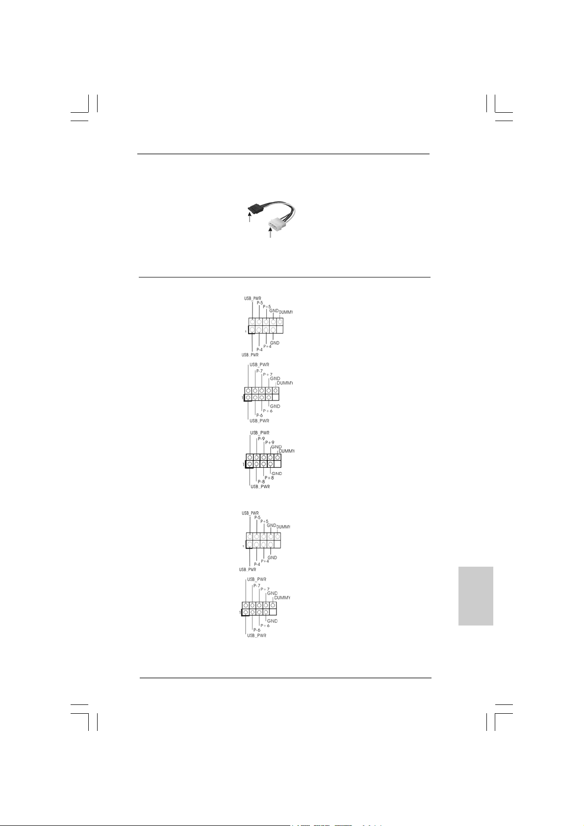
N73PV-S:
USB 2.0 Headers Besides four default USB 2.0
(9-pin US4_5) ports on the I/O panel, there are
(see p.2 No. 26) three USB 2.0 headers on this
motherboard. Each USB 2.0
header can support two USB
2.0 ports.
(9-pin USB6_7)
(see p.2 No. 25)
(9-pin USB8_9)
(see p.2 No. 24)
N73V-S:
USB 2.0 Headers Besides four default USB 2.0
(9-pin US4_5) ports on the I/O panel, there are
(see p.3 No. 25) two USB 2.0 headers on this
motherboard. Each USB 2.0
header can support two USB
2.0 ports.
(9-pin USB6_7)
(see p.3 No. 24)
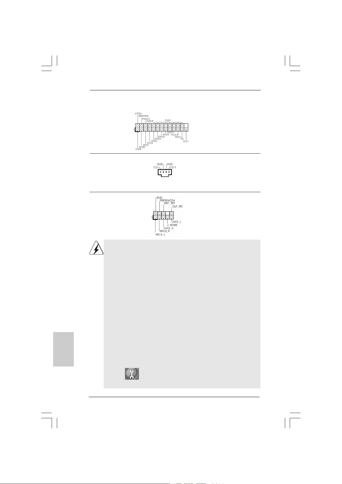
Print Port Header This is an interface for print
(25-pin LPT1) port cable that allows
(see p.2/3 No. 16) convenient connection of printer
devices.
1818
1818
18
ASRock N73PV-S / N73V-S Motherboard
EnglishEnglish
EnglishEnglish
English
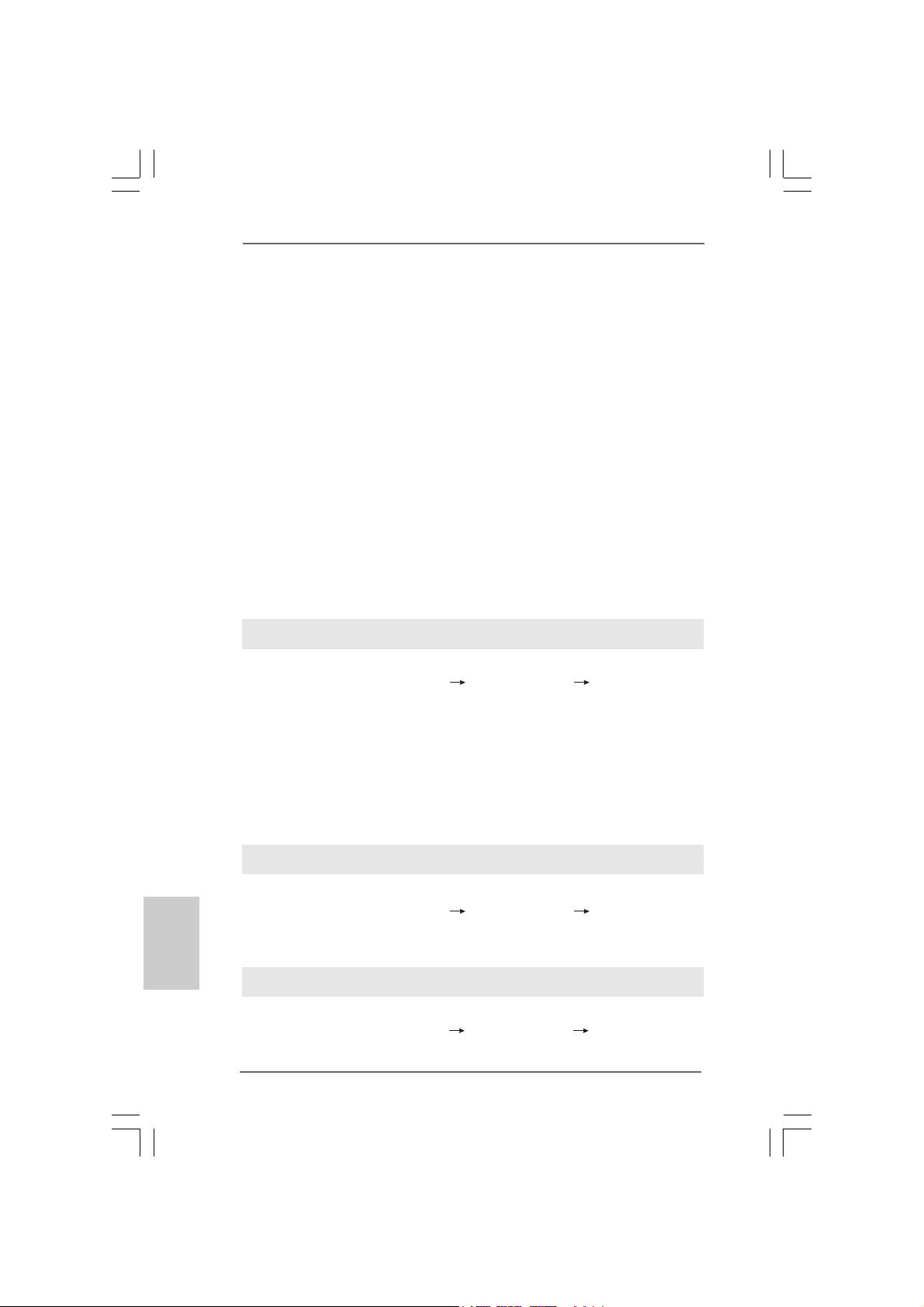
System Panel Hea der This header a ccommodate s
(9-pin PANEL1) several system front panel
(see p.2/3 No. 14) functions.
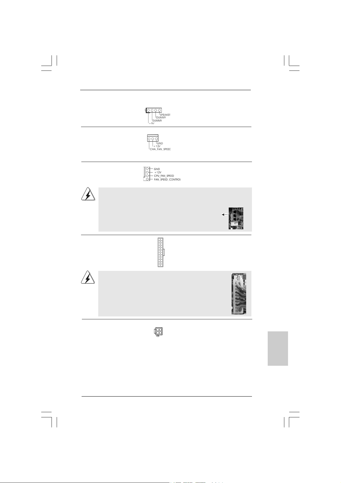
1. High Definition Audio supports Jack Sensing, but the panel wire on
the chassis must support HDA to function correctly. Please follow the
instruction in our manual and chassis manual to install your system.
2. If you use AC’97 audio panel, please install it to the front panel audio
header as below:
A. Connect Mic_IN (MIC) to MIC2_L.
B. Connect Audio_R (RIN) to OUT2_R and Audio_L (LIN) to OUT2_L.
C. Connect Ground (GND) to Ground (GND).
D. MIC_RET and OUT_RET are for HD audio panel only. You don’t
need to connect them for AC’97 audio panel.
E. Enter BIOS Setup Utility. Enter Advanced Settings, and then select
Chipset Configuration. Set the Front Panel Control option from
[Auto] to [Enabled].
F. Enter Windows system. Click the icon on the lower right hand
taskbar to enter Realtek HD Audio Manager.
For Windows
®
XP / XP 64-bit OS:
Click “Audio I/O”, select “Connector Settings” , choose
“Disable front panel jack detection”, and save the change by
clicking “OK”.
For Windows
®
Vista
TM
/ Vista
TM
64-bit OS:
Click the right-top “Folder” icon , choose “Disable front
panel jack detection”, and save the change by clicking “OK”.
Front Panel Audio Header This is an interface f or front
(9-pin HD_AUDIO1) panel audio cable that allows
(see p.2/3 No. 18) convenient connection and
control of audio devices.
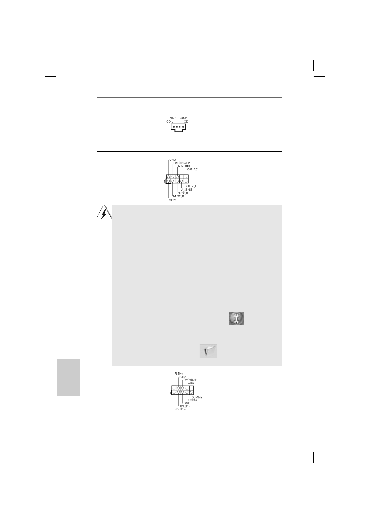
Internal Audio Connectors This connector allows you
(4-pin CD1) to receive stereo audio input
(CD1: see p.2/3 No. 19) from sound sources such as
a CD-ROM, D VD-ROM, TV
tuner card, or MPEG card.
CD1
1919
1919
19
ASRock N73PV-S / N73V-S Motherboard
EnglishEnglish
EnglishEnglish
English
ATX 12V Connector Plea se connect an A TX 12V
(4-pin ATX12V1) power supply to this connector.
(see p.2 No. 27 or p.3 No. 26)
ATX Power Conne ctor Plea se connect an ATX power
(24-pin ATXPWR1) supply to this connector.
(see p.2/3 No. 6)
12
1
24
13
20-Pin ATX Power Supply Installation
Though this motherboard provides 24-pin ATX power connector,
it can still work if you adopt a traditional 20-pin ATX power supply.
To use the 20-pin ATX power supply, please plug your power
supply along with Pin 1 and Pin 13.
12
1
24
13
Chassis Fa n Connector Please connect a cha ssis fan
(3-pin CHA_FAN1) cable to this connector and
(see p.2/3 No. 9) match the black wire to the
ground pin.
CPU Fan Connector Please connect a CPU fan cable
(4-pin CPU_FAN1) to this connector and match
(see p.2/3 No. 4) the black wire to the ground pin.
Though this motherboard provides 4-Pin CPU fan (Quiet Fan) support, the 3-Pin
CPU fan still can work successfully even without the fan speed control function.
If you plan to connect the 3-Pin CPU fan to the CPU fan connector on this
motherboard, please connect it to Pin 1-3.
3-Pin Fan Installation
Pin 1-3 Connected
1
2
3
4
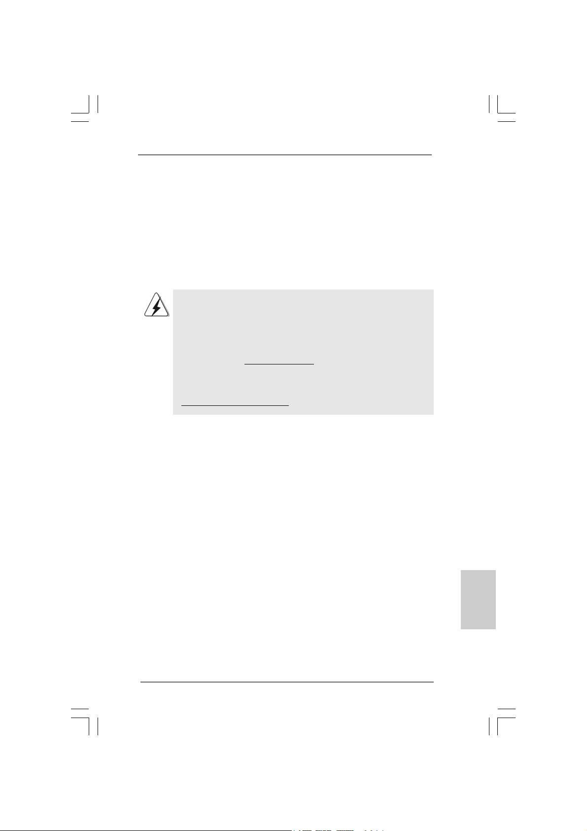
Chassis Spea ker He ader Please connect the chassis
(4-pin SPEAKER 1) speaker to this hea der.
(see p.2/3 No. 15)
2020
2020
20
ASRock N73PV-S / N73V-S Motherboard
EnglishEnglish
EnglishEnglish
English
2.9.2 Installing Windows2.9.2 Installing Windows
2.9.2 Installing Windows2.9.2 Installing Windows
2.9.2 Installing Windows
®®
®®
®
Vista Vista
Vista Vista
Vista
TMTM
TMTM
TM
/ Vista / Vista
/ Vista / Vista
/ Vista
TMTM
TMTM
TM
64-bit Without 64-bit Without
64-bit Without 64-bit Without
64-bit Without
RAID F RAID F
RAID F RAID F
RAID F
unctionsunctions
unctionsunctions
unctions
If you want to install Windows
®
Vista
TM
/ Windows
®
Vista
TM
64-bit on your SATA / SATAII
HDDs without RAID functions, please follow below steps.
Using SATA / SATAII HDDs without NCQ a nd Hot Plug function s
STEP 1: Set Up BIOS.
A. Enter BIOS SETUP UTILITY Advanced screen IDE Configuration.
B. Set the “SATA Operation Mode” option to [IDE].
STEP 2: Install Windows
®
Vista
TM
/ Vista
TM
64-bit OS on your system.
2.82.8
2.82.8
2.8
Driver Installation GuideDriver Installation Guide
Driver Installation GuideDriver Installation Guide
Driver Installation Guide
To install the drivers to your system, plea se insert the support CD to your optical drive
first. Then, the drivers compatible to your system ca n be auto-detected and listed on
the support CD driver page. Please follow the order from up to bottom side to install
those required drivers. Therefore, the drivers you install can work properly.
2.92.9
2.92.9
2.9
Installing WindowsInstalling Windows
Installing WindowsInstalling Windows
Installing Windows
®®
®®
®
XP / XP 64-bit / Vista XP / XP 64-bit / Vista
XP / XP 64-bit / Vista XP / XP 64-bit / Vista
XP / XP 64-bit / Vista
TM TM
TM TM
TM
/ Vista/ Vista
/ Vista/ Vista
/ Vista
TMTM
TMTM
TM
64-bit W64-bit W
64-bit W64-bit W
64-bit W
ithout RAID Fithout RAID F
ithout RAID Fithout RAID F
ithout RAID F
unctionsunctions
unctionsunctions
unctions
If you want to install Windows
®
XP, Windows
®
XP 64-bit, Windows
®
Vista
TM
or Windows
®
Vista
TM
64-bit on your SATA / SATAII HDDs without RAID functions, please f ollow below
procedures according to the OS you install.
2.9.1 Installing Windows2.9.1 Installing Windows
2.9.1 Installing Windows2.9.1 Installing Windows
2.9.1 Installing Windows
®®
®®
®
XP / XP 64-bit Without RAID XP / XP 64-bit Without RAID
XP / XP 64-bit Without RAID XP / XP 64-bit Without RAID
XP / XP 64-bit Without RAID
F F
F F
F
unctionsunctions
unctionsunctions
unctions
If you want to install Windows
®
XP / Windows
®
XP 64-bit on your SA TA / SATAII HDDs
without RAID functions, please follow below steps.
Using SATA / SATAII HDDs without NCQ a nd Hot Plug function s
STEP 1: Set Up BIOS.
A. Enter BIOS SETUP UTILITY Advanced screen IDE Configuration.
B. Set the “SATA Operation Mode” option to [IDE].
STEP 2: Install Windows
®
XP / XP 64-bit OS on your system.
Using SATA / SATAII HDDs with NCQ and Hot Plug functions
STEP 1: Set Up BIOS.
A. Enter BIOS SETUP UTILITY Advanced screen IDE Configuration.
B. Set the “SATA Operation Mode” option to [AHCI].

2121
2121
21
ASRock N73PV-S / N73V-S Motherboard
2.102.10
2.102.10
2.10
Installing WindowsInstalling Windows
Installing WindowsInstalling Windows
Installing Windows
®
XP / XP 64-bit / Vista XP / XP 64-bit / Vista
XP / XP 64-bit / Vista XP / XP 64-bit / Vista
XP / XP 64-bit / Vista
TM TM
TM TM
TM
//
//
/
VistaVista
VistaVista
Vista
TMTM
TMTM
TM
64-bit W 64-bit W
64-bit W 64-bit W
64-bit W
ith RAID Fith RAID F
ith RAID Fith RAID F
ith RAID F
unctionsunctions
unctionsunctions
unctions
If you want to install Windows
®
XP / XP 64-bit / Vista
TM
/ Vista
TM
64-bit on your SATA /
SATAII HDDs with RAID functions, ple a se refer to the document at the f ollowing path in
the Support CD for detailed procedures:
..\ RAID Installation Guide
EnglishEnglish
EnglishEnglish
English
STEP 2: Install Windows
®
Vista
TM
/ Vista
TM
64-bit OS on your system.
Insert the Windows
®
Vista
TM
/ Windows
®
Vista
TM
64-bit optical disk into the optical drive
to boot your system, and follow the instruction to install Windows
®
Vista
TM
/ Windows
®
Vista
TM
64-bit OS on your system. When you see “Where do you want to install Windows?
” page, please insert the ASRock Support CD into your optical drive, and click the “Loa d
Driver” button on the left on the bottom to load the NVIDIA
®
AHCI drivers. NVIDIA
®
AHCI
drivers are in the following path in our Support CD:
(There are two ASRock Support CD in the motherboard gift box pack, please
choose the one for Windows
®
Vista
TM
/ Vista
TM
64-bit.)
.. \ I386 \ AHCI_Vista (For Windows
®
Vista
TM
OS)
.. \ AMD64\ AHCI_Vista64 (For Windows
®
Vista
TM
64-bit OS)
After that, please insert Windows
®
Vista
TM
/ Windows
®
Vista
TM
64-bit optical disk into
the optical drive again to continue the installation.
2.112.11
2.112.11
2.11
Untied Overclocking TUntied Overclocking T
Untied Overclocking TUntied Overclocking T
Untied Overclocking T
echnologyechnology
echnologyechnology
echnology
This motherboard supports Untied Overclocking Technology, which means during
overclocking, FSB enjoys better margin due to fixed PCI / PCIE buses. Before you
enable Untied Overclocking function, plea se enter “Overclock Mode” option of BIOS setup
to set the selection from [Auto] to [CPU, PCIE, Async.]. Therefore, CPU FSB is untied
during overclocking, but PCI / PCIE buses are in the fixed mode so that FSB can operate
under a more stable overclocking environment.
Please refer to the warning on page 7 for the possible overclocking risk
before you apply Untied Overclocking Technology.

2222
2222
22
ASRock N73PV-S / N73V-S Motherboard
3. BIOS Information3. BIOS Information
3. BIOS Information3. BIOS Information
3. BIOS Information
The Flash Memory on the motherboard stores BIOS Setup Utility. When you start up
the computer, please press <F2> during the Power-On-Self-Test (POST) to enter
BIOS Setup utility; otherwise, POST continues with its test routines. If you wish to
enter BIOS Setup after POST, please restart the system by pressing <Ctl> + <Alt> +
<Delete>, or pressing the reset button on the system chassis. The BIOS Setup
program is designed to be user-friendly. It is a menu-driven program, which allows
you to scroll through its various sub-menus and to select among the predetermined
choices. For the detailed information about BIOS Setup, please refer to the User
Manual (PDF file) contained in the Support CD.
4. Software Support CD information
This motherboard supports various Microsoft
®
Windows
®
operating systems: XP /
XP 64-bit / Vista
TM
/ Vista
TM
64-bit. The Support CD that came with the motherboard
contains necessary drivers and useful utilities that will enhance motherboard features.
To begin using the Support CD, insert the CD into your CD-ROM drive. It will display
the Main Menu automatically if “AUTORUN” is enabled in your computer. If the Main
Menu does not appear automatically, locate and double-click on the file “ASSETUP.
EXE” from the BIN folder in the Support CD to display the menus.
EnglishEnglish
EnglishEnglish
English
2323
2323
23
ASRock N73PV-S / N73V-S Motherboard
1. Einführung1. Einführung
1. Einführung1. Einführung
1. Einführung
Wir danken Ihnen für den Kauf des ASRock N73PV-S / N73V-S Motherboard, ein
zuverlässiges Produkt, welches unter den ständigen, strengen Qualitätskontrollen von
ASRock gefertigt wurde. Es bietet Ihnen exzellente Leistung und robustes De sign, gemäß
der Verpflichtung von ASRock zu Qualität und Halbarkeit.
Diese Schnellinstallationsanleitung führt in das Motherboard und die schrittweise
Installation ein. Details über das Motherboard finden Sie in der
Bedienungsanleitung auf der Support-CD.
Da sich Motherboard-Spezifikationen und BIOS-Software verändern können,
kann der Inhalt dieses Handbuches ebenfalls jederzeit geändert werden. Für
den Fall, dass sich Änderungen an diesem Handbuch ergeben, wird eine neue
Version auf der ASRock-Website, ohne weitere Ankündigung, verfügbar sein.
Die neuesten Grafikkarten und unterstützten CPUs sind auch auf der
ASRock-Website aufgelistet.
ASRock-Website: http://www.asrock.com
Wenn Sie technische Unterstützung zu Ihrem Motherboard oder spezifische
Informationen zu Ihrem Modell benötigen, besuchen Sie bitte unsere
Webseite:
www.asrock.com/support/index.asp
1.1 Kartoninhalt
ASRock N73PV-S / N73V-S Motherboard
(Micro ATX-Formfaktor: 24.4 cm x 17.8 cm; 9.6 Zoll x 7.0 Zoll)
ASRock N73PV-S / N73V -S Schnellin stallationsa nle itung
ASRock N73PV-S / N73V-S Support-CD
Ein 80-adriges Ultra-A T A 66/100/133 IDE-Fla chbandk abel (optional)
Ein Serial A TA (SATA) -Datenk abel (option al)
Ein Serial AT A (SATA) -Fe stplattenstromk abel (optional)
Ein I/O Panel Shield
DeutschDeutsch
DeutschDeutsch
Deutsch
2424
2424
24
ASRock N73PV-S / N73V-S Motherboard
DeutschDeutsch
DeutschDeutsch
Deutsch
1.21.2
1.21.2
1.2
SpezifikationenSpezifikationen
SpezifikationenSpezifikationen
Spezifikationen
Plattform - Micro ATX-Formfaktor: 24.4 cm x 17.8 cm; 9.6 Zoll x 7.0 Zoll
CPU - LGA 775 für Intel
®
Core
TM
2 Extreme / Core
TM
2 Quad / Core
TM
2 Duo / Pentium
®
Dual Core / Celeron
®
Dual Core / Celeron
®
unterstützt Quad Core Yorkfield und Dual Core W olfdale
Prozessoren
- FSB1333/1066/800/533MHz
- Unterstützt Hyper-Threading-Technologie
(siehe VORSICHT 1)
- Unterstützt Untied-Übertaktungstechnologie
(siehe VORSICHT 2)
- Unterstützt EM64T -CPU
Chipsatz - NVIDIA
®
GeForce 7100 / nForce 630i (N73PV -S)
- NVIDIA
®
GeForce 7050 / nForce 610i (N73V -S)
Speicher - 2 x Steckplätze für DDR2
- Unterstützt DDR2 800/667/533 non-ECC, ungepufferter
Speicher
- Max. Kapazität de s Systemspeichers: 16GB
(siehe VORSICHT 3)
Erweiterungs- - 1 x PCI Express x16-Steckplätze
steckplätze - 1 x PCI Express x1-Steckplätze
- 2 x PCI -Steckplätze
Onboard-VGA - Integrierte N VIDIA
®
GeForce7100 (N73PV-S)
- Integrierte N VIDIA
®
GeForce7050 (N73V-S)
- DX9.0 VGA, Pixel Shader 3.0
- Maximal gemeinsam genutzter Speicher 256 MB
(siehe VORSICHT 4)
Audio - 5.1 CH Windows
®
Vista
TM
Premium Level HD Audio
(ALC662 Audio Codec)
LAN - Realtek PHY RTL8201EL
- Speed: 10/100 Ethernet
- Unterstützt W a ke-On-LAN
E/A-Anschlüsse I/O Panel
an der - 1 x PS/2-Mausanschluss
Rückseite - 1 x PS/2-Tastaturanschluss
- 1 x Serieller port: COM1
- 1 x VGA port
- 4 x Standard-USB 2.0-Anschlüsse
- 1 x RJ-45 LAN Port mit LED (ACT/LINK LED und SPEED LED)
- HD Audiobuchse: Audioeinga ng / Lautsprecher vorne /
Mikrofon

2525
2525
25
ASRock N73PV-S / N73V-S Motherboard
Anschlüsse - 4 x SATAII-Anschlüsse, unterstützt bis 3.0 Gb/s
Datenübertragungsrate, unterstützt RAID (RAID 0, RAID 1,
RAID 0+1, JBOD und RAID 5), NCQ, AHCI und “Hot Plug”
Funktionen (siehe VORSICHT 5)
* RAID 0+1 und RAID 5-Funktionen gelten für N73PV-S Nur
- 1 x ATA133 IDE-Anschlüsse (Unterstützt bis 2 IDE-Geräte)
- 1 x F DD-Anschlüsse
- 1 x Druckerport-Anschlussleiste
- CPU/Gehäuse-Lüfteranschluss
- 24-pin ATX-Netz-Header
- 4-pin anschluss für 12V-ATX-Netzteil
- Interne Audio-Anschlüsse
- Anschluss für Audio auf der Gehäusevorderseite
- 3 x USB 2.0-Anschlüsse (unterstützt 6 USB 2,0-Ports)
(N73PV-S) (siehe VORSICHT 6)
- 2 x USB 2.0-Anschlüsse (unterstützt 4 USB 2,0-Ports)
(N73V-S) (siehe VORSICHT 6)
BIOS - 4Mb AMI BIOS
- AMI legal BIOS mit U nterstützung für “Plug and Play”
- ACPI 1.1-Weckfunktionen
- JumperFree-Modus
- SMBIOS 2.3.1
- Unterstützt Smart BIOS
Support-CD - Treiber, Dienstprogra mme, Antivirussoftware (Probeversion)
Einzigartige - ASRock OC Tuner (siehe VORSICHT 7)
Eigenschaft - Intelligent Energy Saver (Intelligente Energiesparfunktion)
(siehe VORSICHT 8)
- Sofortstart
- Hybrid Booster:
- Schrittloser CPU-Frequenz-Kontrolle (siehe VORSICHT 9)
- ASRock U-COP (siehe VORSICHT 10)
- Boot Failure Guard (B.F.G. – Systemstartfehlerschutz)
Hardware Monitor - Überwachung der CPU-T emperatur
- Motherboardtemperaturerkennung
- Drehzahlmessung für CPU-Lüfter
- Drehzahlmessung für Gehäuselüfter
- CPU-Lüftergeräuschdämpfung
- Spannungsüberwachung: +12V, +5V, +3.3V, Vcore
Betriebssysteme - Unterstützt Microsoft
®
Windows
®
XP / XP 64-Bit / Vista
TM
/
Vista
TM
64-Bit
Zertifizierungen - FCC, CE
* Für die ausführliche Produktinformation, besuchen Sie bitte unsere Website:
http://www.asrock.com
DeutschDeutsch
DeutschDeutsch
Deutsch
2626
2626
26
ASRock N73PV-S / N73V-S Motherboard
DeutschDeutsch
DeutschDeutsch
Deutsch
WARNUNG
Beachten Sie bitte, dass Overclocking, einschließlich der Einstellung im BIOS, Anwenden
der Untied Overclocking-Technologie oder V erwenden von Overclocking-Werkzeugen von
Dritten, mit einem gewissen Risiko behaftet ist. Overclocking kann sich nachteilig auf die
Stabilität Ihres Systems auswirken oder sogar Komponenten und Geräte Ihres Systems
beschädigen. Es geschieht dann auf eigene Gefahr und auf Ihre Kosten. Wir übernehmen
keine Verantwortung für mögliche Schäden, die aufgrund von Overclocking verursacht
wurden.
VORSICHT!
1. Die Einstellung der “Hyper-Threading Technology”, finden Sie auf
Seite 39 des auf der Support-CD enthaltenen Benutzerhandbuches
beschrieben.
2. Dieses Motherboard unterstützt die Untied-Übertaktungstechnologie.
Unter “Entkoppelte Übertaktungstechnologie” auf Seite 21 finden Sie
detaillierte Informationen.
3. Durch Betriebssystem-Einschränkungen kann die tatsächliche
Speichergröße weniger als 4 GB betragen, da unter Windows
®
XP und
Windows
®
Vista™ etwa s Speicher zur Nutzung durch das System reserviert
wird. Unter Windows
®
XP 64-bit und Windows
®
Vista
™
64-bit mit 64-Bit-CPU
besteht diese Einschränkung nicht.
4. Die Maximalspeichergröße ist von den Chipshändler definiert und
umgetauscht. Bitte überprüfen Sie NVIDIA
®
website für die neuliche
Information.
5. Bevor Sie eine SATA II Festplatte mit dem SATA II Anschluss verbinden,
lesen Sie bitte die “Anleitung zur SATA II Festplatteneinrichtung“ auf
Seite 24, um Ihre SATA II Festplatte in den SATA II Modus
umzuschalten. SATA-Festplatten können Sie auch direkt mit dem SATA
II-Anschluss verbinden.
6. Das Power Management für USB 2.0 arbeitet unter Microsoft
®
Windows
®
Vista
TM
64-Bit / Vista
TM
/ XP 64-Bit / XP SP1 oder SP2
einwandfrei.
7. Es ist ein benutzerfreundlicher ASRock Übertaktenswerkzeug, das
erlaubt, dass Sie Ihr System durch den Hardware-Monitor Funktion zu
überblicken und Ihre Hardware-Geräte übertakten, um die beste
Systemleistung unter der Windows
®
Umgebung zu erreichen.
Besuchen Sie bitte unsere Website für die Operationsverfahren von
ASRock OC Tuner. ASRock-Website: http://www.asrock.com
8. Mit einem fortschrittlichen, eigenständigen Hard- und Softwaredesign
nutzt der Intelligent Energy Saver eine revolutionäre Technologie, die
bisher unerreichte Energieeinsparungen ermöglicht. Mit anderen
Worten: Sie verbrauchen besonders wenig Energie und erreichen
einen hohen Wirkungsgrad, ohne dass dies zu Lasten der
Rechenleistung geht. Auf unseren Internetseiten finden Sie einige
Erläuterungen zur Funktionsweise des Intelligent Energy Saver.
ASRock-Website: http://www.asrock.com
2727
2727
27
ASRock N73PV-S / N73V-S Motherboard
1.3 Einstellung der Jumper1.3 Einstellung der Jumper
1.3 Einstellung der Jumper1.3 Einstellung der Jumper
1.3 Einstellung der Jumper
Die Abbildung verdeutlicht, wie Jumper
gesetzt werden. Werden Pins durch
Jumperkappen verdeckt, ist der Jumper
“gebrückt”. Werden keine Pins durch
Jumperkappen verdeckt, ist der Jumper
“offen”. Die Abbildung zeigt einen 3-Pin
Jumper dessen Pin1 und Pin2 “gebrückt” sind,
bzw. es befindet sich eine Jumper-Kappe
auf diesen beiden Pins.
Jumper Einstellun
PS2_USB_PW1 Überbrücken Sie Pin2, Pin3, um
(siehe S.2/3, Punkt 1) +5VSB (Standby) zu setzen
und die PS/2 oder USB-
We ckfunktionen zu aktivieren.
Hinweis: Um +5VSB nutzen zu können, muss das Netzteil auf dieser Leitung 2A
oder mehr leisten können.
CMOS löschen
(CLRCMOS1, 3-Pin jumper)
(siehe S.2/3, Punkt 10)
Hinweis: CLRCMOS1 erlaubt Ihnen das Löschen der CMOS-Daten. Diese
beinhalten das System-Passwort, Datum, Zeit und die verschiedenen
BIOS-Parameter. Um die Systemparameter zu löschen und auf die
Werkseinstellung zurückzusetzen, schalten Sie bitte den Computer ab
und entfernen das Stromkabel. Benutzen Sie eine Jumperkappe, um die
Pin 2 und Pin 3 an CLRCMOS1 für 5 Sekunden kurzzuschließen. Bitte
vergessen Sie nicht, den Jumper wieder zu entfernen, nachdem das
CMOS gelöscht wurde. Bitte vergessen Sie nicht, den Jumper wieder zu
entfernen, nachdem das CMOS gelöscht wurde. W enn Sie den CMOS-
Gebrückt Offen
CMOS
löschen
Default-
Einstellung
9. Obwohl dieses Motherboard stufenlose Steuerung bietet, wird
Overclocking nicht empfohlen. Frequenzen, die über den für den
jeweiligen Prozessor vorgesehenen liegen, können das System
instabil werden lassen oder die CPU beschädigen.
10. Wird eine Überhitzung der CPU registriert, führt das System einen
automatischen Shutdown durch. Bevor Sie das System neu starten,
prüfen Sie bitte, ob der CPU-Lüfter am Motherboard richtig funktioniert,
und stecken Sie bitte den Stromkabelstecker aus und dann wieder ein.
Um die Wärmeableitung zu verbessern, bitte nicht vergessen, etwas
Wärmeleitpaste zwischen CPU und Kühlkörper zu sprühen.
DeutschDeutsch
DeutschDeutsch
Deutsch
2828
2828
28
ASRock N73PV-S / N73V-S Motherboard
DeutschDeutsch
DeutschDeutsch
Deutsch
Serial A TA- (SAT A-) SJedes Ende des SATA
Datenkabel Datenkabels kann an die SATA
(Option) / SATAII Festplatte oder das
SATAII Verbindungsstück auf
dieser Hauptplatine
angeschlossen werden.
die rotgestreifte Seite auf Stift 1
1.4 Anschlüsse1.4 Anschlüsse
1.4 Anschlüsse1.4 Anschlüsse
1.4 Anschlüsse
Anschlussleisten sind KEINE Jumper. Setzen Sie KEINE Jumperkappen
auf die Pins der Anschlussleisten. Wenn Sie die Jumperkappen auf die
Anschlüsse setzen, wird das Motherboard permanent beschädigt!
Anschluss Beschreibung
Anschluss für das
Floppy-Laufwerk
(33-Pin FLOPPY1)
(siehe S.2/3, Punkt 17)
Hinweis: Achten Sie darauf, dass die rotgestreifte Seite des Ka bel mit der Stift 1-
Seite des An schlusses verbunden wird.
Primärer IDE-Anschluss (blau)
(39-pin IDE1, siehe S.2/3, Punkt 7)
Blauer Anschluss Schwarzer Anschluss
zum Motherboard zur Festplatte
80-adriges ATA 66/100/133 Kabel
Hinweis: Details entnehmen Sie bitte den Anweisungen Ihres IDE-Gerätehändlers.
Seriell-ATAII-Anschlüsse Diese vier Serial A T AII-
(SATAII_1: siehe S.2/3 - No. 8) (SAT AII-)V erbínder unterstützten
(SATAII_2: siehe S.2/3 - No. 13) SAT A-Datenkabel für interne
(SATAII_3: siehe S.2/3 - No. 11) Ma ssenspeichergeräte. Die
(SATAII_4: siehe S.2/3 - No. 12) a ktuelle SAT AII-Schnittstelle
ermöglicht eine
Datenübertragungsrate bis
3,0 Gb/s.
Inhalt gleich nach dem Aktualisieren des BIOS löschen müssen, müssen
Sie zuerst das System starten und dann wieder ausschalten, bevor Sie den
CMOS-Inhalt löschen.
SATAII_1 SATAII_3
SATAII_2 SATAII_4
2929
2929
29
ASRock N73PV-S / N73V-S Motherboard
Verbindung zum
Netzteil
Verbindung zum
SATA-HDD-Stromanschluss
N73PV-S:
USB 2.0-Header Zusätzlich zu den vier
(9-pol. USB4_5) üblichen USB 2.0-Ports an den
(siehe S.2 - Nr. 26) I/O-Anschlüssen befinden sich
drei USB 2.0-Anschlussleisten
am Motherboard. Pro USB 2.0-
Anschlussleiste werden zwei
(9-pol. USB6_7) USB 2.0-Ports unterstützt.
(siehe S.2 - Nr. 25)
(9-pol. USB8_9)
(siehe S.2 - Nr. 24)
Serial A TA- (SATA-) Verbinden Sie das schwarze
Stromversorgungskabel Ende des SATA-Netzkabels mit
(Option) dem Netzan schluss am
Laufwerk. Verbinden Sie dann
das weiße Ende des SATA-
Stromversorgungskabels mit
dem Stromanschluss des
Netzteils.
DeutschDeutsch
DeutschDeutsch
Deutsch
N73V-S:
USB 2.0-Header Zusätzlich zu den vier
(9-pol. USB4_5) üblichen USB 2.0-Ports an den
(siehe S.3 - Nr. 25) I/O-Anschlüssen befinden sich
zwei USB 2.0-Anschlussleisten
am Motherboard. Pro USB 2.0-
Anschlussleiste werden zwei
(9-pol. USB6_7) USB 2.0-Ports unterstützt.
(siehe S.3 - Nr. 24)
3030
3030
30
ASRock N73PV-S / N73V-S Motherboard
1. High Definition Audio unterstützt Jack Sensing (automatische Erkennung
falsch angeschlossener Geräte), wobei jedoch die Bildschirmverdrahtung
am Gehäuse HDA unterstützen muss, um richtig zu funktionieren.
Beachten Sie bei der Installation im System die Anweisungen in unserem
Handbuch und im Gehäusehandbuch.
2. Wenn Sie die AC’97-Audioleiste verwenden, installieren Sie diese wie
nachstehend beschrieben an der Front-Audioanschlussleiste:
A. Schließen Sie Mic_IN (MIC) an MIC2_L an.
B. Schließen Sie Audio_R (RIN) an OUT2_R und Audio_L (LIN) an
OUT2_L an.
C. Schließen Sie Ground (GND) an Ground (GND) an.
D. MIC_RET und OUT_RET sind nur für den HD-Audioanschluss gedacht.
Diese Anschlüsse müssen nicht an die AC’97-Audioleiste
angeschlossen werden.
E. Rufen Sie das BIOS-Setup-Dienstprogramm auf. Wechseln Sie zu
Erweiterte Einstellungen und wählen Sie Chipset-Konfiguration. Setzen
Sie die Option Frontleistenkontrolle von [Automatisch] auf [Aktiviert].
F. Rufen Sie das Windows-System auf. Klicken Sie auf das Symbol in der
Taskleiste unten rechts, um den Realtek HD Audio-Manager aufzurufen.
Für Windows
®
XP / XP 64-Bit Betriebssystem:
Klicken Sie auf “Audio-E/A”, wählen Sie die “Anschlusseinstellungen”
, wählen Sie “Erkennung der Frontleistenbuchse deaktivieren”
und speichern Sie die Änderung durch Klicken auf “OK”.
Anschluss für Audio auf Dieses Interface zu eine m
der Gehäusevorderseite Audio-Panel auf der Vorderseite
(9-Pin HD_AUDIO1) Ihres Gehäuses, ermöglicht
(siehe S.2/3, Punkt 18) Ihnen eine bequeme
Kontrolle über Audio-Geräte.
DeutschDeutsch
DeutschDeutsch
Deutsch
Druckerport-Anschlussleiste Dies ist eine Schnittstelle zum
(25-pol. LPT1) Anschluss eines Druckerport-
(siehe S.2/3 - No. 16) Kabels, mit dem Sie passende
Drucker auf einfache Weise
anschließen können.
Interne Audio-Anschlüsse Diese ermöglichen Ihnen Stereo-
(4-Pin CD1) Signalquellen, wie z. B. CD-ROM,
(CD1: siehe S.2/3, Punkt 19) DV D-ROM, TV-T uner oder
MPEG-Karten mit Ihrem System
zu verbinden.
CD1
 Loading...