


H81 Pro BTC R2.0
Table of contents
 Loading...

Version 1.0
Published August 2016
Copyright©2016 ASRock INC. All rights reserved.
Copyright Notice:
No part of this documentation may be reproduced, transcribed, transmitted, or
translated in any language, in any form or by any means, except duplication of
documentation by the purchaser for backup purpose, without written consent of
ASRock Inc.
Products and corporate names appearing in this documentation may or may not
be registered trademarks or copyrights of their respective companies, and are used
only for identication or explanation and to the owners’ benet, without intent to
infringe.
Disclaimer:
Specications and information contained in this documentation are furnished for
informational use only and subject to change without notice, and should not be
constructed as a commitment by ASRock. ASRock assumes no responsibility for
any errors or omissions that may appear in this documentation.
With respect to the contents of this documentation, ASRock does not provide
warranty of any kind, either expressed or implied, including but not limited to
the implied warranties or conditions of merchantability or tness for a particular
purpose.
In no event shall ASRock, its directors, ocers, employees, or agents be liable for
any indirect, special, incidental, or consequential damages (including damages for
loss of prots, loss of business, loss of data, interruption of business and the like),
even if ASRock has been advised of the possibility of such damages arising from any
defect or error in the documentation or product.
is device complies with Part 15 of the FCC Rules. Operation is subject to the following
two conditions:
(1) this device may not cause harmful interference, and
(2) this device must accept any interference received, including interference that
may cause undesired operation.
CALIFORNIA, USA ONLY
e Lithium battery adopted on this motherboard contains Perchlorate, a toxic substance
controlled in Perchlorate Best Management Practices (BMP) regulations passed by the
California Legislature. When you discard the Lithium battery in California, USA, please
follow the related regulations in advance.
“Perchlorate Material-special handling may apply, see ww w.dtsc.ca.gov/hazardouswaste/
perchlorate”
ASRock Website: http://www.asrock.com

AUSTRALIA ONLY
Our goods come with guarantees that cannot be excluded under the Australian Consumer
Law. You are entitled to a replacement or refund for a major failure and compensation for
any other reasonably foreseeable loss or damage caused by our goods. You are also entitled
to have the goods repaired or replaced if the goods fail to be of acceptable quality and the
failure does not amount to a major failure. If you require assistance please call ASRock Tel
: +886-2-28965588 ext.123 (Standard International call charges apply)
e terms HDMI™ and HDMI High-Denition Multimedia Interface, and the HDMI
logo are trademarks or registered trademarks of HDMI Licensing LLC in the United
States and other countries.

Contents
Chapter 1 Introduction 1
1.1 Package Contents 1
1.2 Specications 2
1.3 Motherboard Layout 6
1.4 I/O Panel 8
Chapter 2 Installation 9
2.1 Installing the CPU 10
2.2 Installing the CPU Fan and Heatsink 13
2.3 Installing Memory Modules (DIMM) 14
2.4 Expansion Slots (PCI Express Slots) 16
2.5 Jumpers Setup 17
2.6 Onboard Headers and Connectors 18
2.7 Installing the 4-pin Power Connectors 22
Chapter 3 Software and Utilities Operation 23
3.1 Installing Drivers 23
3.2 Intel® Smart Connect Technology 24
3.3 ASRock Live Update & APP Shop 29
3.3.1 UI Overview 29
3.3.2 Apps 30
3.3.3 BIOS & Drivers 33
3.3.4 Setting 34
Chapter 4 UEFI SETUP UTILITY 35

4.1 Introduction 35
4.1.1 UEFI Menu Bar 35
4.1.2 Navigation Keys 36
4.2 Main Screen 37
4.3 OC Tweaker Screen 38
4.4 Advanced Screen 46
4.4.1 CPU Conguration 47
4.4.2 Chipset Conguration 49
4.4.3 Storage Conguration 51
4.4.4 Intel® Smart Connect Technology 52
4.4.5 Super IO Conguration 53
4.4.6 ACPI Conguration 55
4.4.7 USB Conguration 57
4.4.8 Trusted Computing 58
4.5 Tools 59
4.6 Hardware Health Event Monitoring Screen 62
4.7 Boot Screen 63
4.8 Security Screen 66
4.9 Exit Screen 67

Chapter 1 Introduction
ank you for purchasing ASRock H81 Pro BTC R 2.0 motherboard, a reliable
motherboard produced under ASRock’s consistently stringent quality control.
It delivers excellent performance with robust design conforming to ASRock’s
commitment to quality and endurance.
In this manual, Chapter 1 and 2 contains the introduction of the motherboard
and step-by-step installation guides. Chapter 3 contains the operation guide of the
soware and utilities. Chapter 4 contains the conguration guide of the BIOS setup.
Becau se the motherboard specications and the BIOS soware might be updated, the
content of this documentation will be subject to change without notice. In case any
modications of this documentation occur, the updated version will be available on
ASRock’s website w ithout f urther notice. If you require technical support relate d to
this motherboard, please vi sit our website for s pecic information about the model
you are using. You may nd the l atest VGA cards and CPU suppor t list on ASRock’s
website a s well. ASRock website ht tp://www.a srock.com.
1.1 Package Contents
ASRock H81 Pro BTC R2.0 Motherboard (ATX Form Factor)
•
ASRock H81 Pro BTC R2.0 Quick Installation Guide
•
ASRock H81 Pro BTC R2.0 Support CD
•
2 x Serial ATA (SATA) Data Cables (Optional)
•
1 x I/O Panel Shield
•
H81 Pro BTC R2.0
English
1

1.2 Specications
Platform
CPU
Chipset
Memory
Expansion
Slot
•
•
•
•
•
•
•
•
•
•
•
•
•
•
ATX Form Factor
All Solid Capacitor design
Supports 4th Generation Intel® CoreTM i7 / i5 / i3 / Xeon® /
Pentium® / Celeron® in LGA1150 Package
Digi Power design
4 Power Phase design
Supports Intel® Turbo Boost 2.0 Technology
Intel® H81
Dual Channel DDR3 Memory Technology
2 x DDR3 DIMM Slots
Supports DDR3 1600/1333/1066 non-ECC, un-buered
memory
Max. capacity of system memory: 16GB
(see CAUTION1)
Supports Intel® Extreme Memory Prole (XMP)1.3/1.2
1 x PCI Express 2.0 x16 Slot (PCIE2: x16 mode)
5 x PCI Express 2.0 x1 Slots
English
2
Graphics
Intel® HD Graphics Built-in Visuals and the VGA outputs can
•
be supported only with processors which are GPU integrated.
Supports Intel® HD Graphics Built-in Visuals : Intel® Quick
•
Sync Video with AVC, MVC (S3D) and MPEG-2 Full
HW Encode1, Intel® InTruTM 3D, Intel® Clear Video HD
Technology, Intel® InsiderTM, Intel® HD Graphics 4400/4600
Pixel Shader 5.0, DirectX 11.1
•
Max. shared memory 512MB
•
* e size of ma ximum shared memory may vary from dierent
operating systems.
Dual Graphics Output: support HDMI and D-Sub ports by
•
independent display controllers
Supports HDMI Technology with max. resolution up to
•
1920x1200 @ 60Hz
Supports D-Sub with max. resolution up to 1920x1200 @
•
60Hz

Audio
LAN
Supports Auto Lip Sync, Deep Color (12bpc), xvYCC and
•
HBR (High Bit Rate Audio) with HDMI Port (Compliant
HDMI monitor is required)
Supports HDCP with HDMI Port
•
Supports Full HD 1080p Blu-ray (BD) playback with HDMI
•
Port
5.1 CH HD Audio (Realtek ALC662 Audio Codec)
•
Supports Surge Protection (ASRock Full Spike Protection)
•
PCIE x1 Gigabit LAN 10/100/1000 Mb/s
•
Realtek RTL8111GR
•
Supports Wake-On-WAN
•
Supports Wake-On-LAN
•
Supports Lightning/ESD Protection (ASRock Full Spike
•
Protection)
Supports LAN Cable Detection
•
Supports Energy Ecient Ethernet 802.3az
•
Supports PXE
•
H81 Pro BTC R2.0
Rear Panel
I/O
1 x PS/2 Mouse Port
•
1 x PS/2 Keyboard Port
•
1 x Serial Port: COM1
•
1 x Parallel Port (ECP/EPP support)
•
1 x D-Sub Port
•
1 x HDMI Port
•
2 x USB 2.0 Ports (Supports ESD Protection (ASRock Full
•
Spike Protection))
2 x USB 3.0 Ports (Supports ESD Protection (ASRock Full
•
Spike Protection))
1 x RJ-45 LAN Port with LED (ACT/LINK LED and SPEED
•
LED)
HD Audio Jacks: Line in / Front Speaker / Microphone
•
English
3

Storage
Connector
BIOS
Feature
2 x SATA3 6.0 Gb/s Connectors, support NCQ, AHCI and
•
Hot Plug
2 x SATA2 3.0 Gb/s Connectors, support NCQ, AHCI and
•
Hot Plug
1 x IR Header
•
1 x COM Port Header
•
1 x Power LED Header
•
1 x TPM Header
•
2 x CPU Fan Connectors (1 x 4-pin, 1 x 3-pin)
•
2 x Chassis Fan Connectors (1 x 4-pin, 1 x 3-pin)
•
1 x Power Fan Connector (3-pin)
•
1 x 24 pin ATX Power Connector
•
1 x 8 pin 12V Power Connector
•
2 x PCIe Power Connectors
•
1 x Front Panel Audio Connector
•
1 x SPDIF Out Connector
•
2 x USB 2.0 Headers (Support 4 USB 2.0 ports) (Supports ESD
•
Protection (ASRock Full Spike Protection))
AMI UEFI Legal BIOS with multilingual GUI support
•
ACPI 1.1 Compliant wake up events
•
SMBIOS 2.3.1 support
•
CPU, DRAM, PCH 1.05V Voltage multi-adjustment
•
English
4
Hardware
Monitor
OS
CPU/Chassis temperature sensing
•
CPU/Chassis/Power Fan Tachometer
•
CPU Quiet Fan (Auto adjust chassis fan speed by CPU tem-
•
perature)
CPU/Chassis Fan multi-speed control
•
Voltage monitoring: +12V, +5V, +3.3V, CPU Vcore
•
Microso® Windows® 10 32-bit / 10 64-bit / 8.1 32-bit / 8.1 64-
•
bit / 8 32-bit / 8 64-bit / 7 32-bit / 7 64-bit
* For the updated Windows® 10 driver, please visit ASRock’s web-
site for details: http://www.asrock.com

FCC, CE, WHQL
Certications
* For detailed product information, please visit our website: http://ww w.asrock.com
Please realize that the re is a certain r isk involved with overclo cking, including adju sting the setting in the BIOS, applying Untied Ove rclocking Technology, or using thirdparty o verclocking tools. Overclocking may aect your system’s stability, or even c ause
damage to the components and dev ices of your system. It should be done at your own
risk and expense. We are not responsible for possible damage cau sed by overclocking.
Due to limitation, the actual memory size may be less than 4GB for the reservation for
system usage under Windows® 32-bit operating systems. Windows® 64-bit operating
systems do not have such limitations. You can use ASRock XFast R AM to utilize the
memor y that Windows® cannot use.
•
ErP/EuP ready (ErP/EuP ready power supply is required)
•
H81 Pro BTC R2.0
English
5
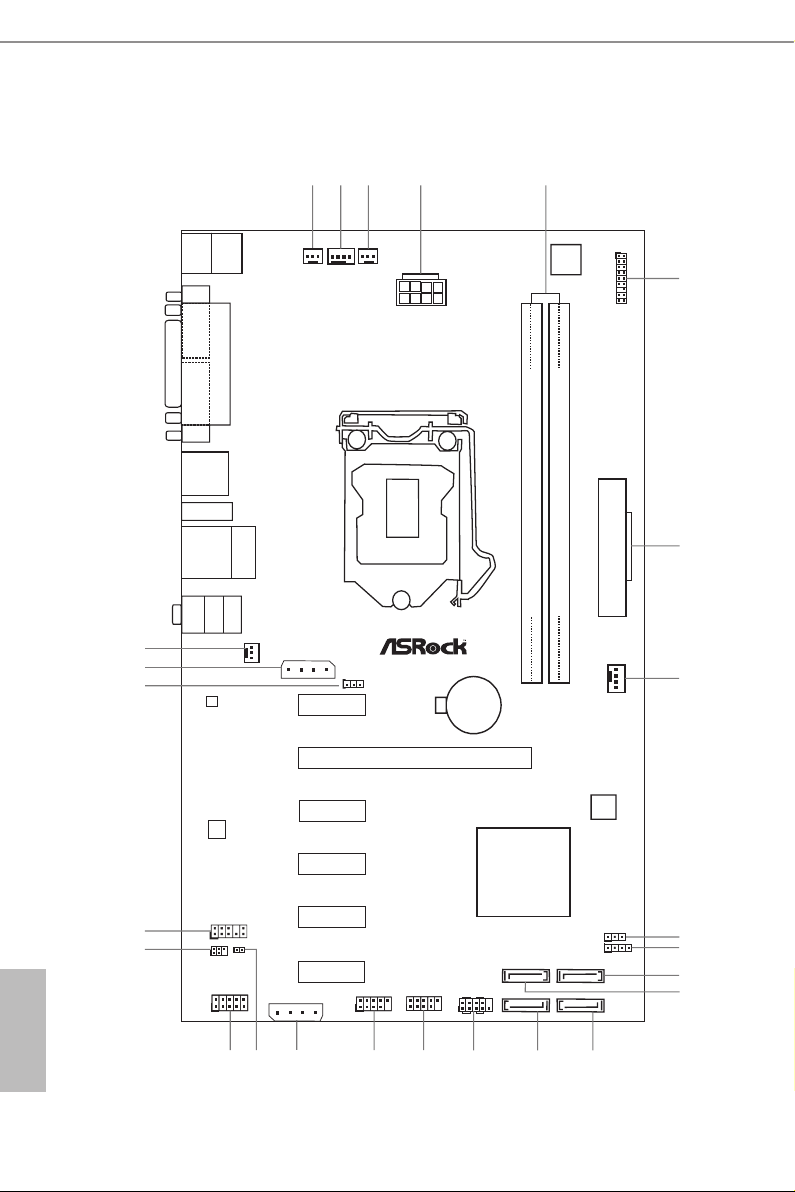
1.3 Motherboard Layout
ATXP WR1
Intel
H81
CMO S
Bat te ry
BIOS
ROM
DDR 3_ A1 (64 bi t, 24 0-p in mo dul e)
DDR 3_ B1 (64 bi t, 24 0-p in mo dul e)
LAN
AUDIO
CODEC
1
HD_AU DIO1
COM2
1
USB_2_3
1
USB_4_5
1
1
SPEAKER1
HDLED RESET
PLED PWRB TN
PANEL1
1
CLRCMO S1
1
SATA3_1
SATA2_1
SATA3_0
SATA2_0
PCIE2
PCIE1
PCIE3
PCIE4
PCIE5
PCIE6
RoH S
H8 1 Pr o BT C
ATX12V 1
IR1
1
PS2
Keyb oar d
PS2
Mous e
Top:
RJ-4 5
USB 2.0
T: USB 0
B: U SB1
USB 3. 0
T:U SB0
B: USB 1
Top:
LINE IN
Cente r:
FRONT
Botto m:
MIC IN
CPU_FAN1
CHA_FAN 1
1 2
3
4
5
6
7
8
9
10
11
12
14
13
15
16
1718
19
20
21
22
23
24
PCIE_P WR1
USB 3 .0
HDMI 1
PARA LL EL P OR T
COM 1
VGA 1
PWR_FAN1CPU_FAN2
TPMS1
1
1
SPDIF_OUT1
CHA_FAN2
1
PLED1
Supe r
I/O
PCIE_P WR2
25
English
6
No. Description
1 CPU Fan Connector (CPU_FAN2)
2 CPU Fan Connector (CPU_FAN1)
3 Power Fan Connector (PWR_FAN1)
4 ATX 12V Power Connector (ATX12V1)
5 2 x 240-pin DDR3 DIMM Slots (DDR3_A1, DDR3_B1)
6 TPM Header (TPMS1)
7 ATX Power Connector (ATXPWR1)
8 Chassis Fan Connector (CHA_FAN1)
9 Power LED Header (PLED1)
10 Chassis Speaker Header (SPEAK ER1)
11 SATA2 Connector (SATA2_0)
12 SATA3 Connector (SATA3_0)
13 SATA2 Connector (SATA2_1)
14 SATA3 Connector (SATA3_1)
15 System Panel Header (PANEL1)
16 USB 2.0 Header (USB_4_5)
17 USB 2.0 Header (USB_2 _3)
18 PCIe Power Connector (PCIE _PWR2)
19 SPDIF Out Connector (SPDIF_OUT)
20 COM Port Header (COM2)
21 Infrared Module Header (IR1)
22 Front Panel Audio Header (HD_ AUDIO1)
23 Clear CMOS Jumper (CLRCMOS1)
24 PCIe Power Connector (PCIE_PWR1)
25 Chassis Fan Connector (CHA_FAN2)
H81 Pro BTC R2.0
English
7
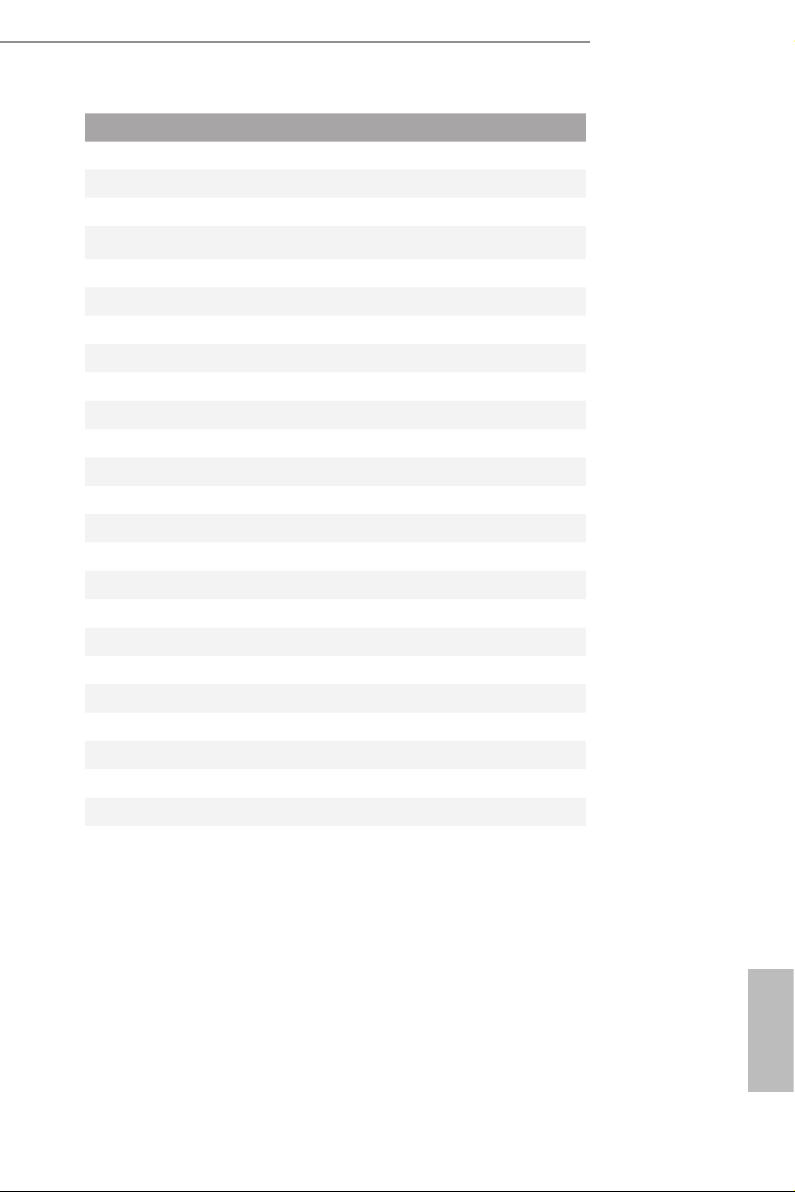
1.4 I/O Panel
1 2 3 4
6
5
7
English
11
No. Description No. Description
1 PS/2 Mouse Port 7 Front Speaker (Lime)
2 Parallel Port 8 Microphone (Pink)
3 USB 3.0 Ports (USB3_01) 9 USB 2.0 Ports (USB_01)
4 HDMI Port 10 D-Sub Port
5 LAN RJ-45 Port* 11 COM Port
6 Line In (Light Blue) 12 PS/2 Keyboard Port
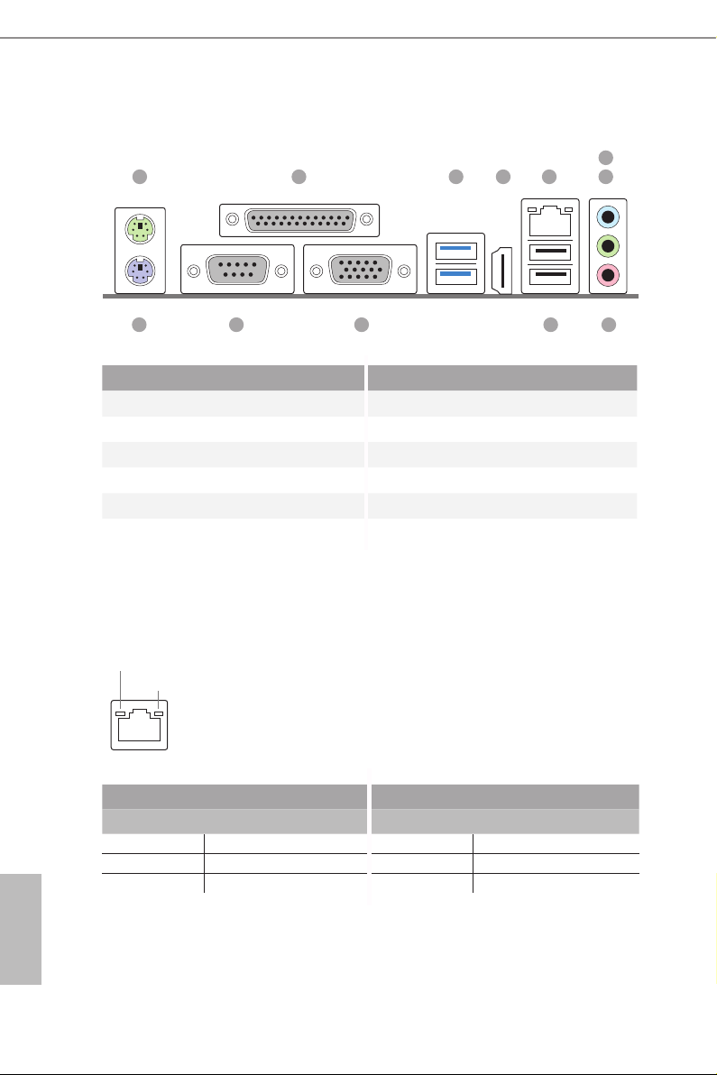
* ere are two LEDs on each LAN port. Please refer to the table below for the LAN port LED indications .
ACT/LINK L ED
SPEED LE D
LAN Por t
Activity / Link LED Speed LED
Status Description Status Description
O No Link O 10Mbps connection
Blinking Data Activity Orange 100Mbps connection
On Link Green 1Gbps connection
891012
8

Chapter 2 Installation
is is an ATX form factor motherboard. Before you install the motherboard, study
the conguration of your chassis to ensure that the motherboard ts into it.
Pre-installation Precautions
Take note of the following precautions before you install motherboard components
or change any motherboard settings.
Make sure to unplug the power cord before installing or removing the motherboard.
•
Failure to do so may cause physical injuries to you and damages to motherboard
components.
In order to avoid damage from static electricity to the motherboard’s components,
•
NEVER place your motherboard directly on a carpet. Also remember to use a grounded
wrist strap or touch a safety grounded object before you handle the components.
Hold components by the edges and do not touch the ICs.
•
Whenever you uninstall any components, place them on a grounded anti-static pad or
•
in the bag that comes with the components.
When placing screws to secure the motherboard to the chassis, please do not over-
•
tighten the screws! Doing so may damage the motherboard.
H81 Pro BTC R2.0
English
9
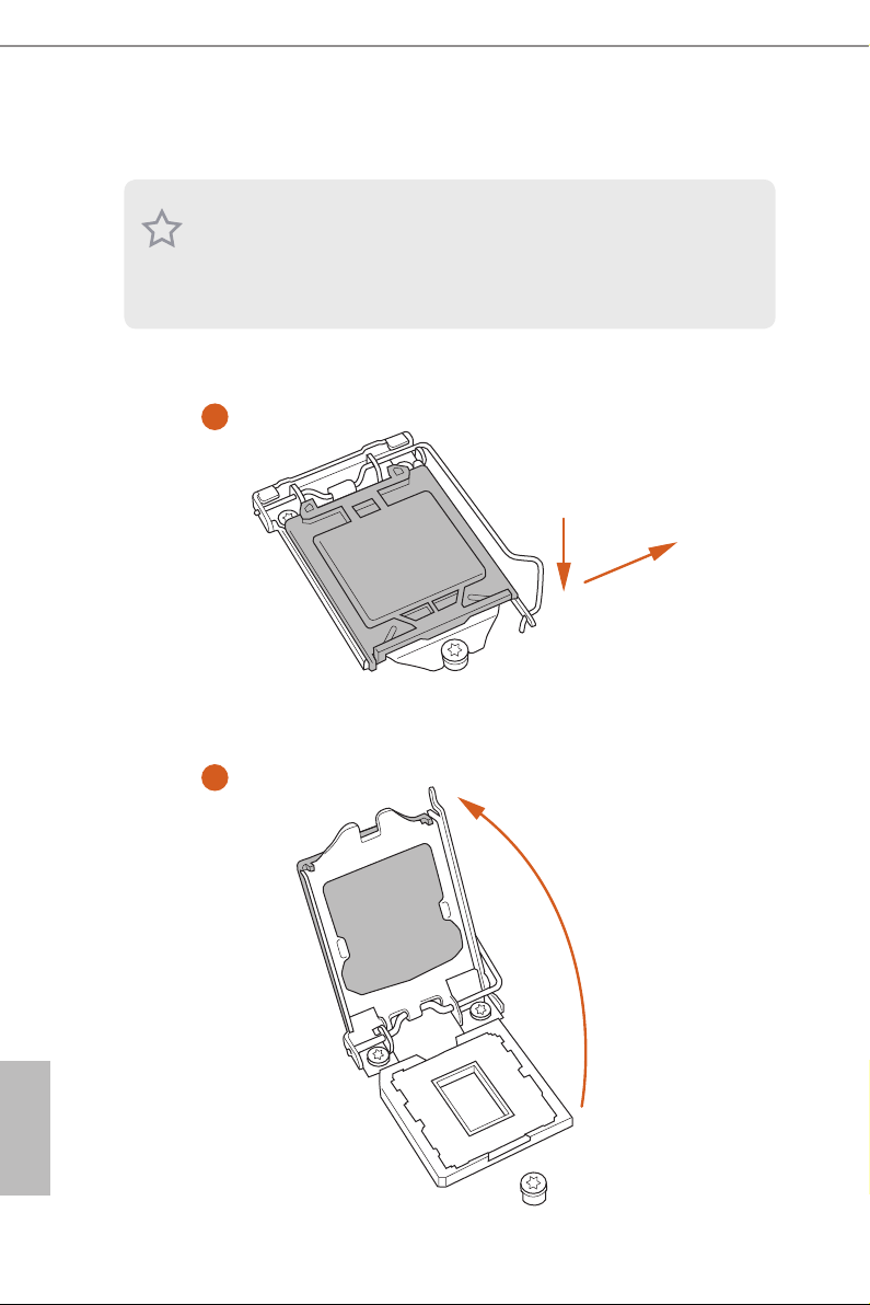
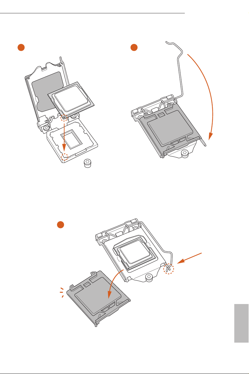
2.1 Installing the CPU
1. Before you inser t the 1150-Pin CPU into the socket, please check if the PnP cap is on
the socket, if the CPU surfa ce is unclean, or if there are any bent pins in the socket.
Do not force to insert the CPU into the socket if above situation is found. Otherwise,
the CPU will be seriously damaged .
2. Unplug all power cables before installing the CPU.
1
A
B
English
10
2
H81 Pro BTC R2.0
3
5
4
11
English

Please save and replace the cover if the processor i s removed. e cover must be placed
if you wish to retur n the motherboard for aer service.
English
12
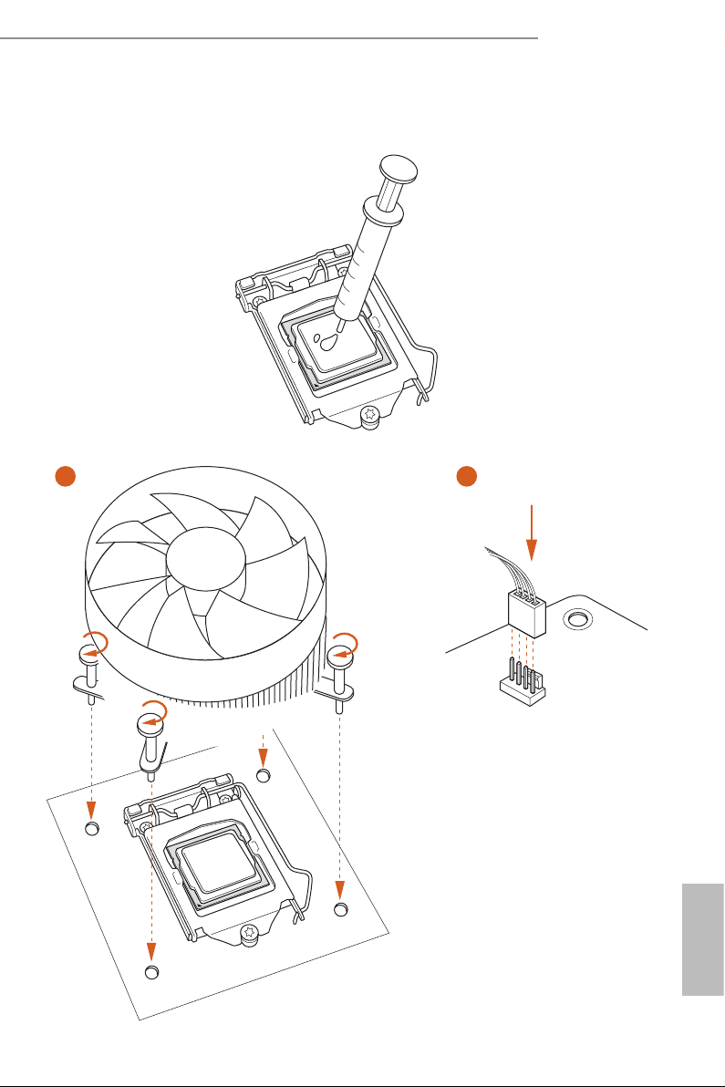
2.2 Installing the CPU Fan and Heatsink
1 2
H81 Pro BTC R2.0
FAN
CPU_
English
13
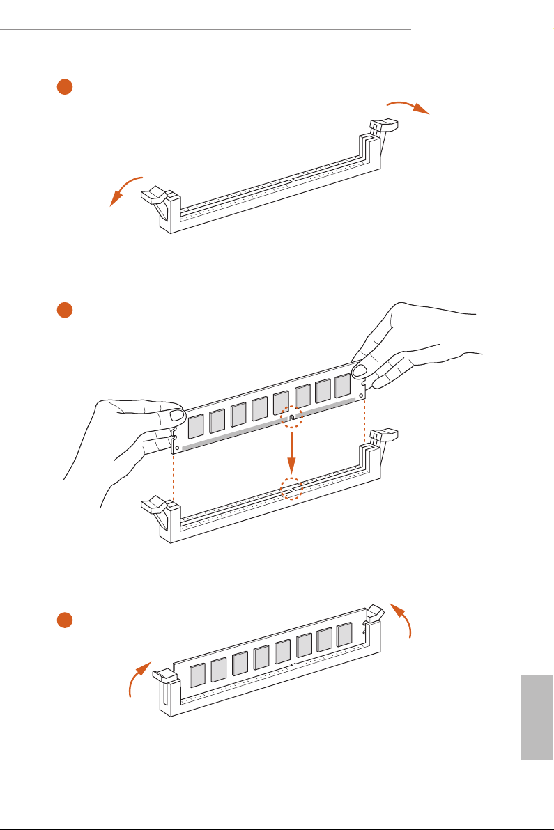
2.3 Installing Memory Modules (DIMM)
is motherboard provides two 240-pin DDR3 (Double Data Rate 3) DIMM slots,
and supports Dual Channel Memory Technology.
1. For dual channel conguration, you always need to install identical (the same
brand, speed , size and chip-type) DDR3 DIMM pairs.
2. It is unable to activate Dual Channel Memory Technology with only one memory
module instal led.
3. It is not allo wed to install a DDR or DDR 2 memory module into a DDR3 slot;
otherwise , this motherboard and DIM M may be damaged.
e DIMM only ts in one correct orientation. It will cause permanent dam age to
the mothe rboard and the DIMM if you force the DIMM into the slot at incor rect
orientation .
English
14
H81 Pro BTC R2.0
1
2
3
English
15
2.4 Expansion Slots (PCI Express Slots)
ere are 6 PCI Express slots on the motherboard.
Before installing an ex pansion card, please make sure that the power supply is
switched o or the power cord is unplugged. Plea se read the documentation of the
expan sion card and mak e necessary hardware settings for the card before you start
the installation.
PCIe slots:
PCIE2 (PCIe 2.0 x16 slot) is used for PCI Express x16 lane width graphics cards.
PCIE1/PCIE3/PCIE4/PCIE5/PCIE6 (PCIe 2.0 x1 slot) is used for PCI Express x1
lane width graphics cards.
English
16
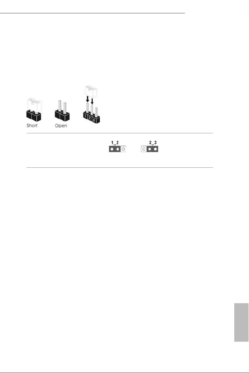
2.5 Jumpers Setup
e illustration shows how jumpers are setup. When the jumper cap is placed on
the pins, the jumper is “Short”. If no jumper cap is placed on the pins, the jumper
is “Open”. e illustration shows a 3-pin jumper whose pin1 and pin2 are “Short”
when a jumper cap is placed on these 2 pins.
Clear CMOS Jumper
(CLRCMOS1)
(see p.6, No. 23)
CLRCMOS1 allows you to clear the data in CMOS. To clear and reset the system
parameters to default setup, please turn o the computer and unplug the power
cord from the power supply. Aer waiting for 15 seconds, use a jumper cap to
short pin2 and pin3 on CLRCMOS1 for 5 seconds. However, please do not clear
the CMOS right aer you update the BIOS. If you need to clear the CMOS when
you just nish updating the BIOS, you must boot up the system rst, and then shut
it down before you do the clear-CMOS action. Please be noted that the password,
date, time, and user default prole will be cleared only if the CMOS battery is
removed.
Clear CMOSDefault
H81 Pro BTC R2.0
17
English
Loading...