


Copyright Notice:
No part of this installation guide may be reproduced, transcribed, transmitted, or translated in any language, in any form or by any means, except duplication of documentation by the purchaser for backup purpose, without written consent of ASRock Inc.
Products and corporate names appearing in this guide may or may not be registered trademarks or copyrights of their respective companies, and are used only for identification or explanation and to the owners’ benefit, without intent to infringe.
Disclaimer:
Specifications and information contained in this guide are furnished for informational use only and subject to change without notice, and should not be constructed as a commitment by ASRock. ASRock assumes no responsibility for any errors or omissions that may appear in this guide.
With respect to the contents of this guide, ASRock does not provide warranty of any kind, either expressed or implied, including but not limited to the implied warranties or conditions of merchantability or fitness for a particular purpose. In no event shall ASRock, its directors, officers, employees, or agents be liable for any indirect, special, incidental, or consequential damages (including damages for loss of profits, loss of business, loss of data, interruption of business and the like), even if ASRock has been advised of the possibility of such damages arising from any defect or error in the guide or product.
This device complies with Part 15 of the FCC Rules. Operation is subject to the following two conditions:
(1)this device may not cause harmful interference, and
(2)this device must accept any interference received, including interference that may cause undesired operation.
CALIFORNIA, USA ONLY
The Lithium battery adopted on this motherboard contains Perchlorate, a toxic substance controlled in Perchlorate Best Management Practices (BMP) regulations passed by the California Legislature. When you discard the Lithium battery in California, USA, please follow the related regulations in advance.
“Perchlorate Material-special handling may apply, see www.dtsc.ca.gov/hazardouswaste/perchlorate”
ASRock Website: http://www.asrock.com
Published April 2009
Copyright©2009 ASRock INC. All rights reserved.
1
English
ASRock K10N78D Motherboard

Motherboard Layout
English
2
1 |
PS2_USB_PW1 Jumper |
19 |
Chassis Speaker Header |
2 |
ATX 12V Power Connector (ATX12V1) |
|
(SPEAKER 1, Purple) |
3 |
CPU Heatsink Retention Module |
20 |
NB Fan Connector (NB_FAN1) |
4 |
AM2 940-Pin CPU Socket |
21 |
System Panel Header (PANEL1, Orange) |
5 |
2 x 240-pin DDR2 DIMM Slots |
22 |
Serial Port Connector (COM1) |
|
(Dual Channel A: DDRII_1, DDRII_2; Yellow) |
23 |
Floppy Connector (FLOPPY1) |
6 |
2 x 240-pin DDR2 DIMM Slots |
24 |
Front Panel Audio Header |
|
(Dual Channel B: DDRII_3, DDRII_4; Orange) |
|
(HD_AUDIO1, Lime) |
7 |
ATX Power Connector (ATXPWR1) |
25 |
HDMI_SPDIF Header |
8 |
Primary IDE Connector (IDE1, Blue) |
|
(HDMI_SPDIF1, Yellow) |
9 |
NVIDIA nForce 720D Chipset |
26 |
PCI Slots (PCI1- 3) |
10 |
SATAII Connector (SATAII_6 (PORT 5), Red) |
27 |
Internal Audio Connector: CD1 (Black) |
11 |
SATAII Connector (SATAII_5 (PORT 4), Red) |
28 |
SPI BIOS Chip |
12 |
SATAII Connector (SATAII_4 (PORT 3), Red) |
29 |
PCI Express x1 Slot (PCIE4, White) |
13 |
SATAII Connector (SATAII_3 (PORT 2), Red) |
30 |
Clear CMOS Jumper (CLRCMOS1) |
14 |
SATAII Connector (SATAII_2 (PORT 1), Red) |
31 |
PCI Express x1 Slot (PCIE3, White) |
15 |
SATAII Connector (SATAII_1 (PORT 0), Red) |
32 |
PCI Express x16 Slot (PCIE2, Green) |
16 |
USB 2.0 Header (USB6_7, Blue) |
33 |
PCI Express x1 Slot (PCIE1, White) |
17 |
USB 2.0 Header (USB10_11, Blue) |
34 |
Chassis Fan Connector (CHA_FAN1) |
18 |
USB 2.0 Header (USB8_9, Blue) |
35 |
CPU Fan Connector (CPU_FAN1) |
ASRock K10N78D Motherboard

I/O Panel
1 |
PS/2 Mouse Port (Green) |
8 |
Microphone (Pink) |
|
* 2 |
LAN RJ-45 Port (LAN1) |
9 |
USB 2.0 |
Ports (USB01) |
3 |
Side Speaker (Gray) |
10 |
USB 2.0 |
Ports (USB23) |
4 |
Rear Speaker (Black) |
11 |
USB 2.0 |
Ports (USB45) |
5 |
Central / Bass (Orange) |
12 |
Optical SPDIF Out Port |
|
6 |
Line In (Light Blue) |
13 |
Coaxial SPDIF Out Port |
|
** 7 |
Front Speaker (Lime) |
14 |
PS/2 Keyboard Port (Purple) |
|
*There are two LED next to the LAN port. Please refer to the table below for the LAN port LED indications.
LAN Port LED Indications
Activity/Link LED |
|
SPEED LED |
ACT/LINK |
SPEED |
|||
|
LED |
LED |
|||||
|
|
|
|
|
|
||
Status |
Description |
|
Status |
|
Description |
|
|
Off |
No Activity |
|
Off |
|
10Mbps connection |
|
|
Blinking |
Data Activity |
|
Orange |
|
100Mbps connection |
|
|
|
|
|
Green |
|
1Gbps connection |
LAN Port |
|
|
|
|
|
|
|
||
**If you use 2-channel speaker, please connect the speaker’s plug into “Front Speaker Jack”. See the table below for connection details in accordance with the type of speaker you use.
TABLE for Audio Output Connection
Audio Output Channels |
Front Speaker |
Rear Speaker |
Central / Bass |
Side Speaker |
|
(No. 7) |
(No. 4) |
(No. 5) |
(No. 3) |
2 |
V |
-- |
-- |
-- |
4 |
V |
V |
-- |
-- |
6 |
V |
V |
V |
-- |
8 |
V |
V |
V |
V |
English
3
ASRock K10N78D Motherboard

To enable Multi-Streaming function, you need to connect a front panel audio cable to the front panel audio header. After restarting your computer, you will find “VIA HD Audio Deck” tool on your system. Please follow below instructions according to the OS you install.
For Windows® XP / XP 64-bit OS: |
|
Please click “VIA HD Audio Deck” icon |
, and click “Speaker”. Then you are allowed to |
select “2 Channel”, “4 Channel”, “6 Channel” or “8 Channel”. Click “Power” to save your change.
For Windows® VistaTM / VistaTM 64-bit OS: |
|
Please click “VIA HD Audio Deck” icon |
, and click “Advanced Options” on the left side |
on the bottom. In “Advanced Options” screen, select “Independent Headphone”, and click “OK” to save your change.
If you enable Multi-Streaming function, Side Speaker function will be disabled. You can only choose to enable either Multi-Streaming function or Side Speaker function.
English
4
ASRock K10N78D Motherboard

1. Introduction
Thank you for purchasing ASRock K10N78D motherboard, a reliable
motherboard produced under ASRock’s consistently stringent quality control. It delivers excellent performance with robust design conforming to ASRock’s commitment to quality and endurance.
This Quick Installation Guide contains introduction of the motherboard and step-by- step installation guide. More detailed information of the motherboard can be found in the user manual presented in the Support CD.
Because the motherboard specifications and the BIOS software might be updated, the content of this manual will be subject to change without notice. In case any modifications of this manual occur, the updated version will be available on ASRock website without further notice. You may find the latest VGA cards and CPU support lists on ASRock website as well. ASRock website http://www.asrock.com
If you require technical support related to this motherboard, please visit our website for specific information about the model you are using. www.asrock.com/support/index.asp
1.1Package Contents
ASRock K10N78D Motherboard
(ATX Form Factor: 12.0-in x 7.5-in, 30.5 cm x 19.1 cm) ASRock K10N78D Quick Installation Guide
ASRock K10N78D Support CD
One 80-conductor Ultra ATA 66/100/133 IDE Ribbon Cable Two Serial ATA (SATA) Data Cables (Optional)
One Serial ATA (SATA) HDD Power Cable (Optional) One I/O Panel Shield
English
5
ASRock K10N78D Motherboard

English
6
1.2Specifications
Platform |
- ATX Form Factor: 12.0-in x 7.5-in, 30.5 cm x 19.1 cm |
|
- Solid Capacitor for CPU power |
CPU |
- Support for Socket AM2+ / AM2 processors: AMD PhenomTM |
|
FX / Phenom / Athlon 64 FX / Athlon 64 X2 Dual-Core / Athlon |
|
X2 Dual-Core / Athlon 64 / Sempron processor |
|
- Support for AM3 processors: AMD PhenomTM II X4 / X3 and |
|
Athlon II X4 / X3 / X2 processors |
|
- AMD LIVE!TM Ready |
|
- Supports AMD’s Cool ‘n’ QuietTM Technology |
|
- FSB 2600 MHz (5.2 GT/s) |
|
- Supports Untied Overclocking Technology (see CAUTION 1) |
|
- Supports Hyper-Transport 3.0 (HT 3.0) Technology |
Chipset |
- NVIDIA® nForce 720D |
Memory |
- Dual Channel DDR2 Memory Technology (see CAUTION 2) |
|
- 4 x DDR2 DIMM slots |
|
- Support DDR2 1066/800/667/533 non-ECC, un-buffered |
|
memory (see CAUTION 3) |
|
- Max. capacity of system memory: 16GB (see CAUTION 4) |
Expansion Slot |
- 1 x PCI Express 2.0 x16 slot (green @ x16 mode) |
|
- 3 x PCI Express x1 slots |
|
- 3 x PCI slots |
Audio |
- 7.1 CH Windows® VistaTM Premium Level HD Audio |
|
(VIA® VT1708S Audio Codec) |
LAN |
- Gigabit LAN 10/100/1000 Mb/s |
|
- Giga PHY Realtek RTL8211CL |
|
- Supports Wake-On-LAN |
|
|
Rear Panel I/O |
I/O Panel |
|
- 1 x PS/2 Mouse Port |
|
- 1 x PS/2 Keyboard Port |
|
- 1 x Coaxial SPDIF Out Port |
|
- 1 x Optical SPDIF Out Port |
|
- 6 x Ready-to-Use USB 2.0 Ports |
|
- 1 x RJ-45 LAN Port with LED (ACT/LINK LED and SPEED LED) |
|
- HD Audio Jack: Side Speaker/Rear Speaker/Central/Bass/ |
|
Line in/Front Speaker/Microphone (see CAUTION 5) |
Connector |
- 6 x SATAII 3.0Gb/s connectors, support RAID (RAID 0, |
|
RAID 1, RAID 0+1, RAID 5 and JBOD), NCQ, AHCI and “Hot |
|
Plug” functions (see CAUTION 6) |
|
- 1 x ATA133 IDE connector (supports 2 x IDE devices) |
ASRock K10N78D Motherboard

|
- 1 x Floppy connector |
|
- 1 x COM port header |
|
- 1 x HDMI_SPDIF header |
|
- CPU/Chassis/NB FAN connector |
|
- 24 pin ATX power connector |
|
- 4 pin 12V power connector |
|
- CD in header |
|
- Front panel audio connector |
|
- 3 x USB 2.0 headers (support 6 USB 2.0 ports) |
|
(see CAUTION 7) |
BIOS Feature |
- 8Mb AMI BIOS |
|
- AMI Legal BIOS |
|
- Supports “Plug and Play” |
|
- ACPI 1.1 Compliance Wake Up Events |
|
- Supports jumperfree |
|
- SMBIOS 2.3.1 Support |
|
- NB Voltage Multi-adjustment |
|
- Supports Smart BIOS |
Support CD |
- Drivers, Utilities, AntiVirus Software (Trial Version) |
Unique Feature |
- ASRock OC Tuner (see CAUTION 8) |
|
- Intelligent Energy Saver (see CAUTION 9) |
|
- Instant Boot |
|
- ASRock Instant Flash (see CAUTION 10) |
|
- Hybrid Booster: |
|
- CPU Frequency Stepless Control (see CAUTION 11) |
|
- ASRock U-COP (see CAUTION 12) |
|
- Boot Failure Guard (B.F.G.) |
|
- ASRock AM2 Boost: ASRock Patented Technology to boost |
|
memory performance up to 12.5% (see CAUTION 13) |
Hardware |
- CPU Temperature Sensing |
Monitor |
- Chassis Temperature Sensing |
|
- CPU/Chassis/NB Fan Tachometer |
|
- CPU Quiet Fan |
|
- Voltage Monitoring: +12V, +5V, +3.3V, CPU Vcore |
|
|
OS |
- Microsoft® Windows® XP / XP Media Center / XP 64-bit / VistaTM |
|
/ VistaTM 64-bit compliant |
Certifications |
- FCC, CE, WHQL |
* For detailed product information, please visit our website: http://www.asrock.com
English
7
ASRock K10N78D Motherboard

English
8
WARNING
Please realize that there is a certain risk involved with overclocking, including adjusting the setting in the BIOS, applying Untied Overclocking Technology, or using the third-party overclocking tools. Overclocking may affect your system stability, or even cause damage to the components and devices of your system. It should be done at your own risk and expense. We are not responsible for possible damage caused by overclocking.
CAUTION!
1.This motherboard supports Untied Overclocking Technology. Please read “Untied Overclocking Technology” on page 22 for details.
2.This motherboard supports Dual Channel Memory Technology. Before you implement Dual Channel Memory Technology, make sure to read the installation guide of memory modules on page 12 for proper installation.
3.Whether 1066MHz memory speed is supported depends on the AM2+ CPU you adopt. If you want to adopt DDR2 1066 memory module on this motherboard, please refer to the memory support list on our website for the compatible memory modules.
ASRock website http://www.asrock.com
4.Due to the operating system limitation, the actual memory size may be less than 4GB for the reservation for system usage under Windows® XP and Windows® VistaTM. For Windows® XP 64-bit and Windows® VistaTM 64bit with 64-bit CPU, there is no such limitation.
5.For microphone input, this motherboard supports both stereo and mono modes. For audio output, this motherboard supports 2-channel, 4-channel, 6-channel, and 8-channel modes. Please check the table on page 3 for proper connection.
6.Before installing SATAII hard disk to SATAII connector, please read the “SATAII Hard Disk Setup Guide” on page 24 of “User Manual” in the support CD to adjust your SATAII hard disk drive to SATAII mode. You can also connect SATA hard disk to SATAII connector
directly.
7.Power Management for USB 2.0 works fine under Microsoft® Windows® VistaTM 64-bit / VistaTM / XP 64-bit / XP SP1 or SP2.
8.It is a user-friendly ASRock overclocking tool which allows you to surveil your system by hardware monitor function and overclock your hardware devices to get the best system performance under Windows® environment. Please visit our website for the operation procedures of ASRock OC Tuner. ASRock website: http://www.asrock.com
ASRock K10N78D Motherboard

9.Featuring an advanced proprietary hardware and software design, Intelligent Energy Saver is a revolutionary technology that delivers unparalleled power savings. The voltage regulator can reduce the number of output phases to improve efficiency when the CPU cores are idle. In other words, it is able to provide exceptional power saving and improve power efficiency without sacrificing computing performance. To use Intelligent Energy Saver function, please enable Cool ‘n’ Quiet option in the BIOS setup in advance. Please visit our website for the operation procedures of Intelligent Energy Saver.
ASRock website: http://www.asrock.com
10.ASRock Instant Flash is a BIOS flash utility embedded in Flash ROM. This convenient BIOS update tool allows you to update system BIOS without entering operating systems first like MS-DOS or Windows®. With this utility, you can press <F6> key during the POST or press <F2> key to BIOS setup menu to access ASRock Instant Flash. Just launch this tool and save the new BIOS file to your USB flash drive, floppy disk or hard drive, then you can update your BIOS only in a few clicks without preparing an additional floppy diskette or other complicated flash utility. Please be noted that the USB flash drive or hard drive must use FAT32/16/12 file system.
11.Although this motherboard offers stepless control, it is not recommended to perform over-clocking. Frequencies other than the recommended CPU bus frequencies may cause the instability of the system or damage the CPU.
12.While CPU overheat is detected, the system will automatically shutdown. Before you resume the system, please check if the CPU fan on the motherboard functions properly and unplug the power cord, then plug it back again. To improve heat dissipation, remember to spray thermal grease between the CPU and the heatsink when you install the PC system.
13.This motherboard supports ASRock AM2 Boost overclocking technology for AM2 CPU. If you enable this function in the BIOS setup, the memory performance will improve up to 12.5%, but the effect still depends on the AM2 CPU you adopt. Enabling this function will overclock the chipset/CPU reference clock. However, we can not guarantee the system stability for all CPU/DRAM configurations. If your system is unstable after AM2 Boost function is enabled, it may not be applicative to your system. You may choose to disable this function for keeping the stability of your system.
English
9
ASRock K10N78D Motherboard

2. Installation
This is an ATX form factor (12.0-in x 7.5-in, 30.5 cm x 19.1 cm) motherboard. Before you install the motherboard, study the configuration of your chassis to ensure that the motherboard fits into it.
Pre-installation Precautions
Take note of the following precautions before you install motherboard components or change any motherboard settings.
Before you install or remove any component, ensure that the power is switched off or the power cord is detached from the power supply. Failure to do so may cause severe damage to the motherboard, peripherals, and/or components.
1.Unplug the power cord from the wall socket before touching any component.
2.To avoid damaging the motherboard components due to static electricity, NEVER place your motherboard directly on the carpet or the like. Also remember to use a grounded wrist strap or touch a safety grounded object before you handle components.
3.Hold components by the edges and do not touch the ICs.
4.Whenever you uninstall any component, place it on a grounded antistatic pad or in the bag that comes with the component.
5.When placing screws into the screw holes to secure the motherboard to the chassis, please do not over-tighten the screws! Doing so may damage the motherboard.
English
1 0
ASRock K10N78D Motherboard
2.1CPU Installation
Step 1. Unlock the socket by lifting the lever up to a 90o angle.
Step 2. Position the CPU directly above the socket such that the CPU corner with the golden triangle matches the socket corner with a small triangle.
Step 3. Carefully insert the CPU into the socket until it fits in place.
The CPU fits only in one correct orientation. DO NOT force the CPU into the socket to avoid bending of the pins.
Step 4. When the CPU is in place, press it firmly on the socket while you push down the socket lever to secure the CPU. The lever clicks on the side tab to indicate that it is locked.
Lever 90°Up |
|
|
|
CPU Golden Triangle |
|
|
SocketCorner |
|
|
Small Triangle |
|
STEP 1: |
STEP 2 / STEP 3: |
STEP 4: |
Lift Up The Socket Lever |
Match The CPU Golden Triangle |
Push Down And Lock |
|
To The Socket Corner Small |
The Socket Lever |
|
Triangle |
|
2.2 Installation of CPU Fan and Heatsink
After you install the CPU into this motherboard, it is necessary to install a larger heatsink and cooling fan to dissipate heat. You also need to spray thermal grease between the CPU and the heatsink to improve heat dissipation. Make sure that the CPU and the heatsink are securely fastened and in good contact with each other. Then connect the CPU fan to the CPU FAN connector (CPU_FAN1, see Page 2, No. 35). For proper installation, please kindly refer to the instruction manuals of the CPU fan and the heatsink.
English
1 1
ASRock K10N78D Motherboard
2.3 Installation of Memory Modules (DIMM)
This motherboard provides four 240-pin DDR2 (Double Data Rate 2) DIMM slots, and supports Dual Channel Memory Technology. For dual channel configuration, you always need to install identical (the same brand, speed, size and chiptype) DDR2 DIMM pair in the slots of the same color. In other words, you have to install identical DDR2 DIMM pair in Dual Channel A (DDRII_1 and DDRII_2; Yellow slots; see p.2 No.5) or identical DDR2 DIMM pair in Dual Channel B (DDRII_3 and DDRII_4; Orange slots; see p.2 No.6), so that Dual Channel Memory Technology can be activated. This motherboard also allows you to install four DDR2 DIMMs for dual channel configuration, and please install identical DDR2 DIMMs in all four slots. You may refer to the Dual Channel Memory Configuration Table below.
English
1 2
Dual Channel Memory Configurations
|
DDRII_1 |
DDRII_2 |
DDRII_3 |
DDRII_4 |
|
(Yellow Slot) |
(Yellow Slot) |
(Orange Slot) |
(Orange Slot) |
|
|
|
|
|
(1) |
Populated |
Populated |
- |
- |
(2) |
- |
- |
Populated |
Populated |
|
|
|
|
|
(3)* |
Populated |
Populated |
Populated |
Populated |
|
|
|
|
|
*For the configuration (3), please install identical DDR2 DIMMs in all four slots.
1.If you want to install two memory modules, for optimal compatibility and reliability, it is recommended to install them in the slots of the same color. In other words, install them either in the set of yellow slots (DDRII_1 and DDRII_2), or in the set of orange slots (DDRII_3 and DDRII_4).
2.If only one memory module or three memory modules are installed in the DDR2 DIMM slots on this motherboard, it is unable to activate the Dual Channel Memory Technology.
3.If a pair of memory modules is NOT installed in the same Dual Channel, for example, installing a pair of memory modules in DDRII_1 and DDRII_3, it is unable to activate the Dual Channel Memory Technology .
4.It is not allowed to install a DDR memory module into DDR2 slot; otherwise, this motherboard and DIMM may be damaged.
ASRock K10N78D Motherboard
Installing a DIMM
Please make sure to disconnect power supply before adding or removing DIMMs or the system components.
Step 1. Unlock a DIMM slot by pressing the retaining clips outward.
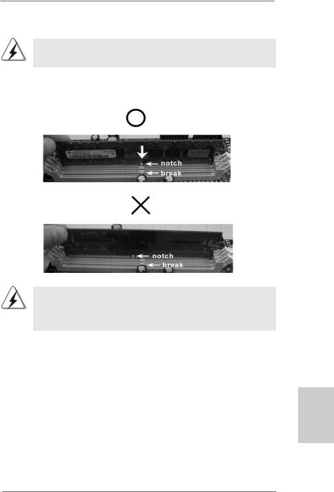
Step 2. Align a DIMM on the slot such that the notch on the DIMM matches the break on the slot.
The DIMM only fits in one correct orientation. It will cause permanent damage to the motherboard and the DIMM if you force the DIMM into the slot at incorrect orientation.
Step 3. Firmly insert the DIMM into the slot until the retaining clips at both ends fully snap back in place and the DIMM is properly seated.
English
1 3
ASRock K10N78D Motherboard

2.4 Expansion Slots (PCI and PCI Express Slots)
There are 3 PCI slots and 4 PCI Express slots on this motherboard.
PCI slots: PCI slots are used to install expansion cards that have the 32-bit PCI interface.
PCIE slots:
PCIE1 / PCIE3 / PCIE4 (PCIE x1 slot; White) is used for PCI Express cards with x1 lane width cards, such as Gigabit LAN card, SATA2 card, etc.
PCIE2 (PCIE x16 slot; Green) is used for PCI Express cards with x16 lane width graphics cards.
Installing an expansion card
Step 1. Before installing the expansion card, please make sure that the power supply is switched off or the power cord is unplugged. Please read the documentation of the expansion card and make necessary hardware settings for the card before you start the installation.
Step 2. Remove the system unit cover (if your motherboard is already installed in a chassis).
Step 3. Remove the bracket facing the slot that you intend to use. Keep the screws for later use.
Step 4. Align the card connector with the slot and press firmly until the card is completely seated on the slot.
Step 5. Fasten the card to the chassis with screws. Step 6. Replace the system cover.
English
1 4
ASRock K10N78D Motherboard

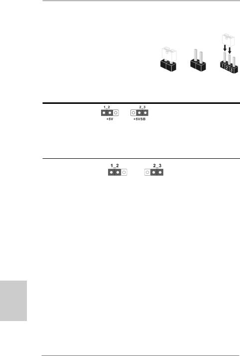
2.5Jumpers Setup
The illustration shows how jumpers are setup. When the jumper cap is placed on pins, the jumper is “Short”. If no jumper cap is placed on pins, the jumper is “Open”. The illustration shows a 3-pin jumper whose pin1 and
pin2 are “Short” when jumper cap is placed on Short Open these 2 pins.
Setting
Short pin2, pin3 to enable +5VSB (standby) for PS/2 or
USB wake up events. Note: To select +5VSB, it requires 2 Amp and higher standby current provided by
power supply.
Clear CMOS Jumper
(CLRCMOS1)
(see p.2, No. 30) Default Clear CMOS
Note: CLRCMOS1 allows you to clear the data in CMOS. The data in CMOS includes system setup information such as system password, date, time, and system setup parameters. To clear and reset the system parameters to default setup, please turn off the computer and unplug the power cord from the power supply. After waiting for 15 seconds, use a jumper cap to short pin2 and pin3 on CLRCMOS1 for 5 seconds. However, please do not clear the CMOS right after you update the BIOS. If you need to clear the CMOS when you just finish updating the BIOS, you must boot up the system first, and then shut it down before you do the clearCMOS action.
English
1 5
ASRock K10N78D Motherboard

English
2.6 Onboard Headers and Connectors
Onboard headers and connectors are NOT jumpers. Do NOT place jumper caps over these headers and connectors. Placing jumper caps over the headers and connectors will cause permanent damage of the motherboard!
•
Floppy Connector
(33-pin FLOPPY1)
(see p.2, No. 23)
the red-striped side to Pin1
Note: Make sure the red-striped side of the cable is plugged into Pin1 side of the connector.
Primary IDE connector (Blue)
(39-pin IDE1, see p.2, No. 8)
connect the blue end |
connect the black end |
to the motherboard |
to the IDE devices |
80-conductor ATA 66/100/133 cable
Note: Please refer to the instruction of your IDE device vendor for the details.
Serial ATA II Connectors
(SATAII_1 (PORT 0): see p.2, No. 15) |
SATAII_6 (PORT 5) |
(SATAII_2 (PORT 1): see p.2, No. 14) |
|
(SATAII_3 (PORT 2): see p.2, No. 13) |
SATAII_5 (PORT 4) |
(SATAII_4 (PORT 3): see p.2, No. 12) |
|
(SATAII_5 (PORT 4): see p.2, No. 11) |
SATAII_4 (PORT 3) |
(SATAII_6 (PORT 5): see p.2, No. 10) |
|
|
SATAII_3 (PORT 2) |
|
SATAII_2 (PORT 1) |
|
SATAII_1 (PORT 0) |
These six Serial ATAII (SATAII) connectors support SATA data cables for internal storage devices. The current SATAII interface allows up to 3.0 Gb/s data transfer rate.
Serial ATA (SATA) |
Either end of the SATA data cable |
Data Cable |
can be connected to the SATA / |
(Optional) |
SATAII hard disk or the SATAII |
|
connector on this motherboard. |
1 6
ASRock K10N78D Motherboard

Serial ATA (SATA) Power Cable
(Optional)
connect to the SATA
HDD power connector
connect to the powersupply
Please connect the black end of SATA power cable to the power connector on each drive. Then connect the white end of SATA power cable to the power connector of the power supply.
USB 2.0 Headers |
Besides six default USB 2.0 |
(9-pin USB10_11) |
ports on the I/O panel, there are |
(see p.2 No. 17) |
three USB 2.0 headers on this |
|
motherboard. Each USB 2.0 |
|
header can support two USB |
|
2.0 ports. |
(9-pin USB8_9) |
|
(see p.2 No. 18) |
|
(9-pin USB6_7) |
|
(see p.2 No. 16) |
|
Internal Audio Connectors |
|
This connector allows you |
|
(4-pin CD1) |
CD1 |
to receive stereo audio input |
|
(CD1: see p.2, No. 27) |
from sound sources such as |
||
|
|||
|
|
a CD-ROM, DVD-ROM, TV |
|
|
|
tuner card, or MPEG card. |
|
|
|
|
|
Front Panel Audio Header |
|
This is an interface for the front |
|
(9-pin HD_AUDIO1) |
|
panel audio cable that allows |
|
(see p.2, No. 24) |
|
convenient connection and |
|
|
|
control of audio devices. |
1.High Definition Audio supports Jack Sensing, but the panel wire on the chassis must support HDA to function correctly. Please follow the instruction in our manual and chassis manual to install your system.
2.If you use AC’97 audio panel, please install it to the front panel audio header as below:
1 7
English
ASRock K10N78D Motherboard

A.Connect Mic_IN (MIC) to MIC2_L.
B.Connect Audio_R (RIN) to OUT2_R and Audio_L (LIN) to OUT2_L.
C.Connect Ground (GND) to Ground (GND).
D.MIC_RET and OUT_RET are for HD audio panel only. You don’t need to connect them for AC’97 audio panel.
E.Enter BIOS Setup Utility. Enter Advanced Settings, and then select Chipset Configuration. Set the Front Panel Control option from [Auto] to [Enabled].
System Panel Header |
This header accommodates |
(9-pin PANEL1) |
several system front panel |
(see p.2, No. 21) |
functions. |
Chassis Speaker Header |
Please connect the chassis |
(4-pin SPEAKER 1) |
speaker to this header. |
(see p.2, No. 19) |
|
|
|
Chassis and NB Fan Connectors |
Please connect the fan cables |
(3-pin CHA_FAN1) |
to the fan connectors and |
(see p.2 No. 34) |
match the black wire to the |
|
ground pin. |
(3-pin NB_FAN1) |
|
(see p.2 No. 20) |
|
English
CPU Fan Connector |
4 3 2 1 |
Please connect the CPU fan |
(4-pin CPU_FAN1) |
|
cable to this connector and |
(see p.2, No. 35) |
|
match the black wire to the |
|
|
ground pin. |
Though this motherboard provides 4-Pin CPU fan (Quiet Fan) support, the 3-Pin CPU fan still can work successfully even without the fan speed control function. If you plan to connect the 3-Pin CPU fan to the CPU fan connector on this motherboard, please connect it to Pin 1-3.
|
|
|
Pin 1-3 Connected |
|
|
|
3-Pin Fan Installation |
|
|
|
|
ATX Power Connector |
12 |
24 |
Please connect an ATX power |
(24-pin ATXPWR1) |
|
|
supply to this connector. |
(see p.2, No. 7) |
|
|
|
|
1 |
13 |
|
1 8
ASRock K10N78D Motherboard

tion
|
Though this motherboard provides 24-pin ATX power connector, 12 |
24 |
|
|
it can still work if you adopt a traditional 20-pin ATX power supply. |
|
|
|
To use the 20-pin ATX power supply, please plug your power |
|
|
|
supply along with Pin 1 and Pin 13. |
|
|
|
|
20-PinATX Power Supply Installation |
13 |
|
|
1 |
|
|
|
|
|
|
|
||
ATX 12V Power Connector |
Please note that it is necessary |
||
(4-pin ATX12V1) |
to connect a power supply with |
||
(see p.2, No. 2) |
ATX 12V plug to this connector. |
||
|
|
Failing to do so will cause power |
|
|
|
up failure. |
|
|
|
||
Serial port Header |
This COM1 header supports a |
||
(9-pin COM1) |
serial port module. |
|
|
(see p.2, No.22) |
|
|
|
HDMI_SPDIFHeader |
HDMI_SPDIF header, providing |
(3-pin HDMI_SPDIF1) |
SPDIF audio output to HDMI VGA |
(see p.2 No. 25) |
card, allows the system to |
|
connect HDMI Digital TV/ |
|
projector/LCD devices. Please |
|
connect the HDMI_SPDIF |
|
connector of HDMI VGA card to |
|
this header. |
|
|
HDMI_SPDIFCable
(Optional)
A. black end
Please connect the black end (A)
C of HDMI_SPDIF cable to the
B
HDMI_SPDIF header on the
Amotherboard. Then connect the white end (B or C) of HDMI_SPDIF cable to the HDMI_SPDIF connector of HDMI VGA card.
B. white end (2-pin) |
C. white end (3-pin) |
English
1 9
ASRock K10N78D Motherboard

2.7Driver Installation Guide
To install the drivers to your system, please insert the support CD to your optical drive first. Then, the drivers compatible to your system can be auto-detected and listed on the support CD driver page. Please follow the order from up to bottom side to install those required drivers. Therefore, the drivers you install can work properly.
2.8Installing Windows® XP / XP 64-bit / VistaTM /
VistaTM 64-bit Without RAID Functions
If you want to install Windows® XP, Windows® XP 64-bit, Windows® VistaTM or Windows® VistaTM 64-bit on your SATA / SATAII HDDs without RAID functions, please follow below procedures according to the OS you install.
2.8.1 Installing Windows® XP / XP 64-bit Without RAID Functions
If you want to install Windows® XP / Windows® XP 64-bit on your SATA / SATAII HDDs without RAID functions, please follow below steps.
English
2 0
Using SATA / SATAII HDDs with NCQ and Hot Plug functions STEP 1: Set Up BIOS.
A. |
Enter BIOS SETUP UTILITY |
|
Advanced screen |
|
IDE Configuration. |
|
|
B. Set the “SATA Operation Mode” option to [IDE].
STEP 2: Make a SATA / SATAII driver diskette.
A. |
Insert the ASRock Support CD into your optical drive to boot your system. |
|
(There are two ASRock Support CD in the motherboard gift box pack, |
|
please choose the one for Windows® XP / XP 64-bit.) |
B.During POST at the beginning of system boot-up, press <F11> key, and then a window for boot devices selection appears. Please select CDROM as the boot device.
C.When you see the message on the screen, “Generate Serial ATA driver diskette [YN]?”, press <Y>.
D.Then you will see these messages,
Please choose:
1.Generate AHCI Driver diskette for WindowsXP
2.Generate RAID Driver diskette for WindowsXP
3.Generate AHCI Driver diskette for WindowsXP64
4.Generate RAID Driver diskette for WindowsXP64
5.Exit
Reboot system now
Press any key to continue
ASRock K10N78D Motherboard
Please insert a floppy diskette into the floppy drive. Select your required item on the list according to the mode you choose and the OS you install. Then press any key.
E.The system will start to format the floppy diskette and copy SATA / SATAII drivers into the floppy diskette.
STEP 3: Set Up BIOS.
Please follow step 1 to set up the BIOS option “SATA Operation Mode” to [AHCI].
STEP 4: Install Windows® XP / XP 64-bit OS on your system.
You can start to install Windows® XP / XP 64-bit on your system. At the beginning of Windows® setup, press F6 to install a third-party AHCI driver. When prompted, insert the SATA / SATAII driver diskette containing the NVIDIA® AHCI driver. After reading the floppy disk, the drivers will be presented. Select the driver to install according to the
OS you install. The drivers are as below:
A.NVIDIA nForce Storage Controller (required) Windows XP
B.NVIDIA nForce Storage Controller (required) Windows XP64
Please select A for Windows® XP in AHCI mode. Please select B for Windows® XP 64bit in AHCI mode.
Using SATA / SATAII HDDs without NCQ and Hot Plug functions STEP 1: Set Up BIOS.
A. |
Enter BIOS SETUP UTILITY |
|
Advanced screen |
|
IDE Configuration. |
|
|
B.Set the “SATA Operation Mode” option to [IDE].
STEP 2: Install Windows® XP / XP 64-bit OS on your system.
2.8.2 Installing Windows® VistaTM / VistaTM 64-bit Without RAID Functions
If you want to install Windows® VistaTM / Windows® VistaTM 64-bit on your SATA / SATAII HDDs without RAID functions, please follow below steps.
Using SATA / SATAII HDDs with NCQ and Hot Plug functions
STEP 1: Set Up BIOS.
A. |
Enter BIOS SETUP UTILITY |
|
Advanced screen |
|
IDE Configuration. |
|
|
B.Set the “SATA Operation Mode” option to [AHCI].
STEP 2: Install Windows® VistaTM / VistaTM 64-bit OS on your system.
Insert the Windows® VistaTM / Windows® VistaTM 64-bit optical disk into the optical drive to boot your system, and follow the instruction to install Windows® VistaTM / Windows® VistaTM 64-bit OS on your system. When you see “Where do you want to install Windows?” page, please insert the ASRock Support CD into your optical drive, and click the “Load Driver” button on the left on the bottom to load the NVIDIA® AHCI drivers. NVIDIA® AHCI drivers are in the following path in our Support CD:
2 1
English
ASRock K10N78D Motherboard

(There are two ASRock Support CD in the motherboard gift box pack, please choose the one for Windows® VistaTM / VistaTM 64-bit.)
.. \ I386 \ AHCI_Vista (For Windows® VistaTM OS)
.. \ AMD64\ AHCI_Vista64 (For Windows® VistaTM 64-bit OS)
After that, please insert Windows® VistaTM / Windows® VistaTM 64-bit optical disk into the optical drive again to continue the installation.
Using SATA / SATAII HDDs without NCQ and Hot Plug functions
STEP 1: Set Up BIOS. |
|
|
|
A. |
Enter BIOS SETUP UTILITY |
Advanced screen |
IDE Configuration. |
B.Set the “SATA Operation Mode” option to [IDE].
STEP 2: Install Windows® VistaTM / VistaTM 64-bit OS on your system.
2.9Installing Windows® XP / XP 64-bit / VistaTM /
VistaTM 64-bit With RAID Functions
If you want to install Windows® XP / XP 64-bit / VistaTM / VistaTM 64-bit on your SATA / SATAII HDDs with RAID functions, please refer to the document at the following path in the Support CD for detailed procedures:
..\ RAID Installation Guide
2.10 Untied Overclocking Technology
This motherboard supports Untied Overclocking Technology, which means during overclocking, FSB enjoys better margin due to fixed PCI / PCIE buses. Before you enable Untied Overclocking function, please enter “Overclock Mode” option of BIOS setup to set the selection from [Auto] to [CPU, PCIE, Async.]. Therefore, CPU FSB is untied during overclocking, but PCI / PCIE buses are in the fixed mode so that FSB can operate under a more stable overclocking environment.
Please refer to the warning on page 8 for the possible overclocking risk before you apply Untied Overclocking Technology.
English
2 2
ASRock K10N78D Motherboard

3. BIOS Information
The Flash Memory on the motherboard stores BIOS Setup Utility. When you start up the computer, please press <F2> during the Power-On-Self-Test (POST) to enter BIOS Setup utility; otherwise, POST continues with its test routines. If you wish to enter BIOS Setup after POST, please restart the system by pressing <Ctl> + <Alt> + <Delete>, or pressing the reset button on the system chassis. The BIOS Setup program is designed to be user-friendly. It is a menu-driven program, which allows you to scroll through its various sub-menus and to select among the predetermined choices. For the detailed information about BIOS Setup, please refer to the User Manual (PDF file) contained in the Support CD.
4. Software Support CD information
This motherboard supports various Microsoft® Windows® operating systems: XP / XP Media Center / XP 64-bit / VistaTM / VistaTM 64-bit. The Support CD that came with the motherboard contains necessary drivers and useful utilities that will enhance motherboard features. To begin using the Support CD, insert the CD into your CD-ROM drive. It will display the Main Menu automatically if “AUTORUN” is enabled in your computer. If the Main Menu does not appear automatically, locate and double-click on the file “ASSETUP. EXE” from the “BIN” folder in the Support CD to display the menus.
English
2 3
ASRock K10N78D Motherboard

1. Einführung
Wir danken Ihnen für den Kauf des ASRock K10N78D Motherboard, ein zuverlässiges Produkt, welches unter den ständigen, strengen Qualitätskontrollen von ASRock gefertigt wurde. Es bietet Ihnen exzellente Leistung und robustes Design, gemäß der Verpflichtung von ASRock zu Qualität und Halbarkeit.
Diese Schnellinstallationsanleitung führt in das Motherboard und die schrittweise Installation ein. Details über das Motherboard finden Sie in der Bedienungsanleitung auf der Support-CD.
Da sich Motherboard-Spezifikationen und BIOS-Software verändern können, kann der Inhalt dieses Handbuches ebenfalls jederzeit geändert werden. Für den Fall, dass sich Änderungen an diesem Handbuch ergeben, wird eine neue Version auf der ASRock-Website, ohne weitere Ankündigung, verfügbar sein. Die neuesten Grafikkarten und unterstützten CPUs sind auch auf der ASRock-Website aufgelistet.
ASRock-Website: http://www.asrock.com
Wenn Sie technische Unterstützung zu Ihrem Motherboard oder spezifische Informationen zu Ihrem Modell benötigen, besuchen Sie bitte unsere Webseite:
www.asrock.com/support/index.asp
1.1 Kartoninhalt
ASRock K10N78D Motherboard
(ATX-Formfaktor: 30.5 cm x 19.1 cm; 12.0 Zoll x 7.5 Zoll)
ASRock K10N78D Schnellinstallationsanleitung
ASRock K10N78D Support-CD
Ein 80-adriges Ultra-ATA 66/100/133 IDE-Flachbandkabel
Zwei Serial ATA (SATA) -Datenkabel (optional)
Ein Serial ATA (SATA) -Festplattenstromkabel (optional)
Ein I/O Shield
Deutsch
2 4
ASRock K10N78D Motherboard

1.2Spezifikationen
Plattform |
- ATX-Formfaktor: 30.5 cm x 19.1 cm; 12.0 Zoll x 7.5 Zoll |
|
- Festkondensator für CPU-Leistung |
CPU |
- Unterstützung für Socket AM2+ / AM2-Prozessoren: AMD |
|
PhenomTM FX / Phenom / Athlon 64 FX / Athlon 64 X2 Dualkern |
|
/ Athlon X2 Dualkern / Athlon 64 / Sempron-Prozessor |
|
- Unterstützung von AM3-Prozessoren: AMD PhenomTM II X4 / |
|
X3 und Athlon X4 / X3 / X2-Prozessor |
|
- AMD LIVE!TM-bereit |
|
- Unterstützt Cool ‘n’ QuietTM-Technologie von AMD |
|
- FSB 2600 MHz (5.2 GT/s) |
|
- Unterstützt Untied-Übertaktungstechnologie |
|
(siehe VORSICHT 1) |
|
- Unterstützt Hyper-Transport- 3.0 (HT 3.0) Technologie |
Chipsatz |
- NVIDIA® nForce 720D |
Speicher |
- Unterstützung von Dual-Kanal-Speichertechnologie |
|
(siehe VORSICHT 2) |
|
- 4 x Steckplätze für DDR2 |
|
- Unterstützt DDR2 1066/800/667/533 non-ECC, ungepufferter |
|
Speicher (siehe VORSICHT 3) |
|
- Max. Kapazität des Systemspeichers: 16GB |
|
(siehe VORSICHT 4) |
Erweiterungs- |
- 1 x PCI Express 2.0 x16-Steckplätze (grün für x16-Modus) |
steckplätze |
- 3 x PCI Express x1-Steckplätze |
|
- 3 x PCI -Steckplätze |
Audio |
- 7.1 CH Windows® VistaTM Premium Level HD Audio |
|
(VIA® VT1708S Audio Codec) |
LAN |
- Gigabit LAN 10/100/1000 Mb/s |
|
- Giga PHY Realtek RTL8211CL |
|
- Unterstützt Wake-On-LAN |
|
|
E/A-Anschlüsse |
I/O Panel |
an der |
- 1 x PS/2-Mausanschluss |
Rückseite |
- 1 x PS/2-Tastaturanschluss |
|
- 1 x Koaxial-SPDIF-Ausgang |
|
- 1 x optischer SPDIF-Ausgang |
|
- 6 x Standard-USB 2.0-Anschlüsse |
|
- 1 x RJ-45 LAN Port mit LED (ACT/LINK LED und SPEED LED) |
|
- HD Audiobuchse: Lautsprecher seitlich / Lautsprecher hinten |
|
/ Mitte/Bass / Audioeingang/ Lautsprecher vorne / Mikrofon |
|
(siehe VORSICHT 5) |
Deutsch
2 5
ASRock K10N78D Motherboard

Deutsch
2 6
|
Anschlüsse |
- 6 x SATAII-Anschlüsse, unterstützt bis 3.0 Gb/s |
|
|
Datenübertragungsrate, unterstützt RAID (RAID 0, RAID 1, |
|
|
RAID 0+1, RAID 5 und JBOD), NCQ, AHCI und “Hot Plug” |
|
|
Funktionen (siehe VORSICHT 6) |
|
|
- 1 x ATA133 IDE-Anschlüsse (Unterstützt bis 2 IDE-Geräte) |
|
|
- 1 x FDD-Anschlüsse |
|
|
- 1 x COM-Anschluss-Header |
|
|
- 1 x HDMI_SPDIF-Anschluss |
|
|
- CPU/Gehäuse/NB-Lüfter-Anschluss |
|
|
- 24-pin ATX-Netz-Header |
|
|
- 4-pin anschluss für 12V-ATX-Netzteil |
|
|
- Interne Audio-Anschlüsse |
|
|
- Anschluss für Audio auf der Gehäusevorderseite |
|
|
- 3 x USB 2.0-Anschlüsse (Unterstützung 6 |
|
|
zusätzlicher USB 2.0-Anschlüsse) (siehe VORSICHT 7) |
|
BIOS |
- 8Mb AMI BIOS |
|
|
- AMI legal BIOS mit Unterstützung für “Plug and Play” |
|
|
- ACPI 1.1-Weckfunktionen |
|
|
- JumperFree-Modus |
|
|
- SMBIOS 2.3.1 |
|
|
- NB Stromspannung Multianpassung |
|
|
- Unterstützt Smart BIOS |
|
|
|
|
Support-CD |
- Treiber, Dienstprogramme, Antivirussoftware |
|
|
(Probeversion) |
|
Einzigartige |
- ASRock OC Tuner (siehe VORSICHT 8) |
|
Eigenschaft |
- Intelligent Energy Saver (Intelligente Energiesparfunktion) |
|
|
(siehe VORSICHT 9) |
|
|
- Sofortstart |
|
|
- ASRock Instant Flash (siehe VORSICHT 10) |
|
|
- Hybrid Booster: |
|
|
- Schrittloser CPU-Frequenz-Kontrolle |
|
|
(siehe VORSICHT 11) |
|
|
- ASRock U-COP (siehe VORSICHT 12) |
|
|
- Boot Failure Guard (B.F.G. – Systemstartfehlerschutz) |
|
|
- ASRock AM2 Boost: ASRocks patentgeschützte |
|
|
Technologie zur Erhöhung der Arbeitsspeicherleistung um |
|
|
bis zu 12,5% (siehe VORSICHT 13) |
|
Hardware Monitor |
- CPU-Temperatursensor |
|
|
- Motherboardtemperaturerkennung |
|
|
- Drehzahlmessung für CPU/Gehäuse/NB-Lüfter |
|
|
- CPU-Lüftergeräuschdämpfung |
|
|
- Spannungsüberwachung: +12V, +5V, +3.3V, Vcore |
|
|
|
ASRock K10N78D Motherboard

Betriebssysteme - Unterstützt Microsoft® Windows® XP / XP Media Center /
XP 64-Bit / VistaTM / VistaTM 64-Bit
Zertifizierungen - FCC, CE, WHQL
*Für die ausführliche Produktinformation, besuchen Sie bitte unsere Website: http://www.asrock.com
WARNUNG
Beachten Sie bitte, dass Overclocking, einschließlich der Einstellung im BIOS, Anwenden der Untied Overclocking-Technologie oder Verwenden von Overclocking-Werkzeugen von Dritten, mit einem gewissen Risiko behaftet ist. Overclocking kann sich nachteilig auf die Stabilität Ihres Systems auswirken oder sogar Komponenten und Geräte Ihres Systems beschädigen. Es geschieht dann auf eigene Gefahr und auf Ihre Kosten. Wir übernehmen keine Verantwortung für mögliche Schäden, die aufgrund von Overclocking verursacht wurden.
VORSICHT!
1.Dieses Motherboard unterstützt die Untied-Übertaktungstechnologie. Unter “Entkoppelte Übertaktungstechnologie” auf Seite 22 finden Sie detaillierte Informationen.
2.Dieses Motherboard unterstützt Dual-Kanal-Speichertechnologie. Vor Implementierung der Dual-Kanal-Speichertechnologie müssen Sie die Installationsanleitung für die Speichermodule auf Seite 12 zwecks richtiger Installation gelesen haben.
3.Ob die Speichergeschwindigkeit 1066 MHz unterstützt wird, hängt von der von Ihnen eingesetzten AM2+-CPU ab. Schauen Sie bitte auf unseren Internetseiten in der Liste mit unterstützten Speichermodulen nach, wenn Sie DDR2 1066-Speichermodule einsetzen möchten.
ASRock-Internetseite: http://www.asrock.com
4.Durch Betriebssystem-Einschränkungen kann die tatsächliche Speichergröße weniger als 4 GB betragen, da unter Windows® XP und Windows® Vista™ etwas Speicher zur Nutzung durch das System reserviert wird. Unter Windows® XP 64-bit und Windows® Vista™ 64-bit mit 64-Bit-CPU besteht diese Einschränkung nicht.
5.Der Mikrofoneingang dieses Motherboards unterstützt Stereound MonoModi. Der Audioausgang dieses Motherboards unterstützt 2-Kanal-, 4- Kanal-, 6-Kanal- und 8-Kanal-Modi. Stellen Sie die richtige Verbindung anhand der Tabelle auf Seite 3 her.
6.Vor Installation der SATAII-Festplatte an den SATAII-Anschluss lesen Sie bitte “Setup-Anleitung für SATAII-Festplatte” auf Seite 24 der “Bedienungsanleitung” auf der Support-CD, um Ihre SATAII-Festplatte dem SATAII-Modus anzugleichen. Sie können die SATA-Festplatte auch direkt mit dem SATAII-Anschluss verbinden.
7.Das Power Management für USB 2.0 arbeitet unter Microsoft® Windows® VistaTM 64-Bit / VistaTM / XP 64-Bit / XP SP1 oder SP2 einwandfrei.
2 7
Deutsch
ASRock K10N78D Motherboard

Deutsch
2 8
8.Es ist ein benutzerfreundlicher ASRock Übertaktenswerkzeug, das erlaubt, dass Sie Ihr System durch den Hardware-Monitor Funktion zu überblicken und Ihre Hardware-Geräte übertakten, um die beste Systemleistung unter der Windows® Umgebung zu erreichen. Besuchen Sie bitte unsere Website für die Operationsverfahren von ASRock OC Tuner. ASRock-Website: http://www.asrock.com
9.Mit einer eigenen, modernen Hardware und speziellem Softwaredesign, bietet der Intelligent Energy Saver eine revolutionäre Technologie zur bisher unerreichten Energieeinsparung. Ein Spannungsregler kann die Anzahl von Ausgangsphasen zur Effektivitätsverbessserung reduzieren, wenn sich die CPU im Leerlauf befindet. Mit anderen Worten: Sie genießen außergewöhnliche Energieeinsparung und verbesserten Wirkungsgrad ohne Leistungseinschränkungen. Wenn Sie die Intelligent Energy Saver-Funktion nutzen möchten, aktivieren Sie zuvor die „Cool ‘n’ Quiet“-Option im BIOS. Weitere Bedienungshinweise zum Intelligent Energy Saver finden Sie auf unseren Internetseiten. ASRock-Internetseite: http://www.asrock.com
10.ASRock Instant Flash ist ein im Flash-ROM eingebettetes BIOS-Flash- Programm. Mithilfe dieses praktischen BIOS-Aktualisierungswerkzeugs können Sie das System-BIOS aktualisieren, ohne dafür zuerst Betriebssysteme wie MS-DOS oder Windows® aufrufen zu müssen. Mit diesem Programm bekommen Sie durch Drücken der <F6>-Taste während des POST-Vorgangs oder durch Drücken der <F2>-Taste im BIOS-Setup-Menü Zugang zu ASRock Instant Flash. Sie brauchen dieses Werkzeug einfach nur zu starten und die neue BIOS-Datei auf Ihrem USB-Flash-Laufwerk, Diskettenlaufwerk oder der Festplatte zu speichern, und schon können Sie Ihr BIOS mit nur wenigen Klickvorgängen ohne Bereitstellung einer zusätzlichen Diskette oder eines anderen komplizierten Flash-Programms aktualisieren. Achten Sie darauf, dass das USB-Flash-Laufwerk oder die Festplatte das Dateisystem FAT32/16/12 benutzen muss.
11.Obwohl dieses Motherboard stufenlose Steuerung bietet, wird Overclocking nicht empfohlen. Frequenzen, die über den für den jeweiligen Prozessor vorgesehenen liegen, können das System instabil werden lassen oder die CPU beschädigen.
12.Wird eine Überhitzung der CPU registriert, führt das System einen automatischen Shutdown durch. Bevor Sie das System neu starten, prüfen Sie bitte, ob der CPU-Lüfter am Motherboard richtig funktioniert, und stecken Sie bitte den Stromkabelstecker aus und dann wieder ein. Um die Wärmeableitung zu verbessern, bitte nicht vergessen, etwas Wärmeleitpaste zwischen CPU und Kühlkörper zu sprühen.
ASRock K10N78D Motherboard

13.Dieses Motherboard unterstützt die ASRock AM2 Boost Übertaktungstechnologie. Wenn Sie diese Funktion im BIOS-Setup aktivieren, wird die Arbeitsspeicherleistung um bis zu 12,5% gesteigert. Die Wirkung hängt aber von der verwendeten AM2 CPU ab. Diese Funktion übertaktet die Standardfrequenz des Chipsatz und der CPU. Dennoch gewähren wir die Systemstabilität nicht bei allen CPU/DRAMKonfigurationen. Wird Ihr System nach dem Aktivieren der AM2 BoostFunktion unstabil, dann ist diese Funktion wahrscheinlich nicht für Ihr System geeignet. Sie können diese Funktion deaktivieren, um die Stabilität Ihres System zu bewahren.
Deutsch
2 9
ASRock K10N78D Motherboard
Deutsch
1.3 Einstellung der Jumper
DieAbbildung verdeutlicht, wie Jumper gesetzt werden. Werden Pins durch Jumperkappen verdeckt, ist der Jumper “gebrückt”. Werden keine Pins durch Jumperkappen verdeckt, ist der Jumper “offen”. Die Abbildung zeigt einen
3-Pin Jumper dessen Pin1 und Pin2 “gebrückt”
sind, bzw. es befindet sich eine Jumper-Kappe Gebrückt Offen auf diesen beiden Pins.
Einstellun
Überbrücken Sie Pin2, Pin3, um
+5VSB (Standby) zu setzen und die PS/2 oder USBWeckfunktionen zu aktivieren.
Um +5VSB nutzen zu können, muss das Netzteil auf dieser Leitung 2A oder mehr leisten können.
CMOS löschen
(CLRCMOS1, 3-Pin jumper)
(siehe S.2, Punkt 30)
DefaultCMOS Einstellung löschen
Hinweis: CLRCMOS1 erlaubt Ihnen das Löschen der CMOS-Daten. Diese beinhalten das System-Passwort, Datum, Zeit und die verschiedenen BIOS-Parameter. Um die Systemparameter zu löschen und auf die Werkseinstellung zurückzusetzen, schalten Sie bitte den Computer ab und entfernen das Stromkabel. Benutzen Sie eine Jumperkappe, um die Pin 2 und Pin 3 an CLRCMOS1 für 5 Sekunden kurzzuschließen. Bitte vergessen Sie nicht, den Jumper wieder zu entfernen, nachdem das CMOS gelöscht wurde. Bitte vergessen Sie nicht, den Jumper wieder zu entfernen, nachdem das CMOS gelöscht wurde. Wenn Sie den CMOSInhalt gleich nach dem Aktualisieren des BIOS löschen müssen, müssen Sie zuerst das System starten und dann wieder ausschalten, bevor Sie den CMOS-Inhalt löschen.
3 0
ASRock K10N78D Motherboard
 Loading...